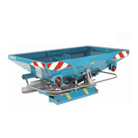
BOGBALLE M Series User manual

Operator's Manual
Spreaders GB


3
Table of Contents
Safety ....................................................................................................................................................... 6
Safety and protection ......................................................................................................................................................................6
Legend ............................................................................................................................................................................................7
Liability .................................................................................................................................................... 8
Liability ............................................................................................................................................................................................8
Check list ................................................................................................................................................. 9
Check list ........................................................................................................................................................................................9
Before every use: ..........................................................................................................................................................................10
Before rst time use: .....................................................................................................................................................................11
After 5-8 hours use: ......................................................................................................................................................................11
After every use: .............................................................................................................................................................................12
Useful hints ...................................................................................................................................................................................13
Quick Guide - M60W, M45W, M35W, L20W with CALIBRATOR or ISOBUS ..................................................................14
1 - Mounting ..................................................................................................................................................................................14
2 - How to set the spreader ..........................................................................................................................................................14
3 - How to do headland spreading ................................................................................................................................................14
4 - How to do normal spreading ....................................................................................................................................................14
Quick Guide - M45, M35, L20, L15 with CALIBRATOR ...................................................................... 15
1 - Mounting ..................................................................................................................................................................................15
2 - How to set the spreader ..........................................................................................................................................................15
3 - How to do headland spreading ................................................................................................................................................15
4 - How to do normal spreading ....................................................................................................................................................15
Quick Guide - M45, M35, L20, L15 with mechanical control ............................................................. 16
1 - Mounting ..................................................................................................................................................................................16
2 - How to set the spreader ..........................................................................................................................................................16
3 - How to do headland spreading ................................................................................................................................................17
4 - How to do normal spreading ....................................................................................................................................................17
Principle sketch .................................................................................................................................... 18
Technical specications ...................................................................................................................... 20
Spread charts ........................................................................................................................................ 21
How to use ....................................................................................................................................................................................21
Calibration and quantity setting .......................................................................................................... 22
Basic principle and denition of standard calibration set point value STD ...................................................................................22
Correct Flow-outlet setting at high/low rates .................................................................................................................................24
Calibration procedures/possibilities M-line & L-line ......................................................................................................................25
MW-line, L20W with CALIBRATOR ZURF or ISOBUS, fully automatic calibration (FAC) ............................................................26
M-line, L20W, L20 & CALIBRATOR ZURF / use of calibration value STD ...................................................................................27
M-line & CALIBRATOR ZURF / use of calibration value STD in MAX ow-outlet position ...........................................................28
M-line & CALIBRATOR ZURF, use of STD calibration value via INPUT ......................................................................................29
M-line, L20W, L20 & CALIBRATOR ZURF, micro granular / small seeds with xed scale ...........................................................30
M-line manual calibration on spreader MC ...................................................................................................................................31
M-line, L20W, L20 & CALIBRATOR ZURF, quick setting via spread chart value .........................................................................33
M45, M35, L20 & CALIBRATOR ZURF by use of S-indicator value .............................................................................................34
M45, M35, L20, L15 & CALIBRATOR ICON by use of S-indicator value .....................................................................................36
M45, M35 & CALIBRATOR ZURF/ICON setting according to ow-outlet position .......................................................................38
L20, L15 & CALIBRATOR ZURF/ ICON setting according to ow-outlet position ........................................................................40
M45, M35, L20, L15 calibration with S-Indicator in combination with hydraulic control ................................................................42

4
Table of Contents
Rest-emptying ....................................................................................................................................... 44
M-line ............................................................................................................................................................................................44
Normal and headland spreading ......................................................................................................... 45
In general ......................................................................................................................................................................................45
To Border ......................................................................................................................................................................................45
From Border ..................................................................................................................................................................................46
Settings for M60W, M45W, M35W, L20W ....................................................................................................................................47
Normal spreading................................................................................................................................................................47
Headland spreading ............................................................................................................................................................47
Settings for M45, M35, L20 ...........................................................................................................................................................49
Normal spreading................................................................................................................................................................49
Headland spreading ............................................................................................................................................................49
Settings for L15 .............................................................................................................................................................................53
Normal spreading................................................................................................................................................................53
Headland spreading ............................................................................................................................................................53
Spreader settings ................................................................................................................................. 56
PTO speed ....................................................................................................................................................................................56
Tilt angle .......................................................................................................................................................................................57
Working height - standard .............................................................................................................................................................58
Working height - late application ...................................................................................................................................................58
Working height - trails ...................................................................................................................................................................59
Quantity setting .............................................................................................................................................................................60
With CALIBRATOR .............................................................................................................................................................60
With mechanical control......................................................................................................................................................60
By use of spread chart only.................................................................................................................................................61
Working width setting ....................................................................................................................................................................62
Spreading vanes ...........................................................................................................................................................................63
Regulation system ................................................................................................................................ 66
Connection rods ............................................................................................................................................................................66
Outlet shutters ..............................................................................................................................................................................66
Practical tests ....................................................................................................................................... 67
Fertiliser analysis ..........................................................................................................................................................................67
D-indicator - Grain size .......................................................................................................................................................67
F-indicator - Grain strength .................................................................................................................................................68
Normal spreading................................................................................................................................................................70
Headland spreading ............................................................................................................................................................71
Optimize spreading .............................................................................................................................. 72
Normal spreading .........................................................................................................................................................................72
Coecient of variation ..................................................................................................................................................................72
Headland spreading EN13739-1 ..................................................................................................................................................73
To Border ......................................................................................................................................................................................73
Headland spreading can be divided into three categories: ...........................................................................................................73
Start and stop points at headlands ...............................................................................................................................................75
Spreading on non rectangular elds .................................................................................................. 76
Principle sketches .........................................................................................................................................................................76
Mechanical control ..............................................................................................................................................................76
Section Control Standard ....................................................................................................................................................76
Section Control Dynamic.....................................................................................................................................................76
Controls ........................................................................................................................................................................................77
M60W, M45W, M35W, L20W with CALIBRATOR ZURF or ISOBUS 77
M45, M35, L20, L15 with CALIBRATOR ICON...................................................................................................................78
M45, M35, L20 with CALIBRATOR ZURF...........................................................................................................................78
M45, M35 with CALIBRATOR ZURF...................................................................................................................................79

5
M60W, M45W, M35W
M45, M35
L20W
L20, L15
=
=
=
=
Colour codes
Table of Contents
Reduced working width ....................................................................................................................... 80
Principle sketches .........................................................................................................................................................................80
Mechanical control and Section Control Standard 80
Section Control Dynamic.....................................................................................................................................................80
Controls ........................................................................................................................................................................................81
M60W, M45W, M35W, L20W with CALIBRATOR ZURF or ISOBUS 81
M45, M35, L20, L15 with CALIBRATOR ICON...................................................................................................................81
M45, M35, L20, with CALIBRATOR ZURF..........................................................................................................................82
M45, M35, L20, L15 with mechanical control......................................................................................................................83
Maintenance and care .......................................................................................................................... 84
Lubrication ....................................................................................................................................................................................84
Nuts and bolts ...............................................................................................................................................................................84
Spreading vanes ...........................................................................................................................................................................84
Normal maintenance .....................................................................................................................................................................85
Friction clutch ................................................................................................................................................................................85
How to clean the friction clutch .....................................................................................................................................................85
Corrosion ............................................................................................................................................... 86
Safety - Axle load .................................................................................................................................. 87
EC-Declaration of conformity .............................................................................................................. 91
Notes ...................................................................................................................................................... 92

6
●Read Operator’s Manual and safety rules before starting.
●Read Operator’s Manual for the PTO shaft.
●Do not leave the tractor cabin without stopping the PTO system of the tractor!
●Turn o tractor engine and all electrical controlling devices during maintenance and other intervention on the
spreader
●Ensure that bystanders maintain a sucient safety distance from the spreader as long as the tractor engine is
on.
●Do not enter the spreader when the tractor engine is on.
●Do not wear loosely tting clothes that could become entangled with moving parts.
●Wear personal protective equipment when necessary or when required by the manufacturer of the fertiliser.
●Stay under the spreader is prohibited.
●Never go between spreader and tractor when engine is started.
●Never enter the spreader using the ladder when the spreader is not mounted to a tractor. The spreader might tilt
over due to unstable weight distribution.
●Safety distance for ying material must be observed.
●Never go behind the spreader with rotating spreading discs.
●Avoid contact with rotating parts.
●Never put hand/object into the hopper with rotating spreading discs.
●Avoid contact as long as parts are moving.
●Never clean the spreader with rotating spreading discs.
●When parking the spreader ensure that the hopper is empty and the ground is solid and horizontal.
Safety and protection
Safety

7
Dieser Dünger-
streuer erfült
die europäische
Umweltnorm
EN 13739-1
This fertiliser spreader
fulfils the European
environmental standard
EN 13739-1
Ce distributeur d'engrais
répond à la norme
environnement
EN 13739-1
Denne gødnings-
spreder opfylder
den europæiske
miljønorm
EN 13739-1
For vort miljø
Für unsere Umwelt
Pour notre environnement
For our environment
xxxx
Legend
Read Operator’s Manual and safety rules before starting.
Never go under a raised spreader.
Never go between spreader and tractor when engine is started.
Never use the ladder when the spreader is not mounted on a tractor.
Safety distance for ying material must be observed.
Never go behind the spreader with rotating spreading discs.
Avoid contact with rotating parts.
Never put hand/object into the hopper with rotating spreading discs.
Avoid contact as long as parts are moving.
Never clean the spreader with rotating spreading discs.
Do not spray water in this area.
Noise level measured inside a closed tractor cabin (level depends on tractor brand and model).
Lashing points for loading and unloading the spreader
Do not step on.
Not designed for boarding purposes.
EN13739-1
Max. loading capacity.
Do not exceed.
Type: Model
No.: Serial number
Year: Manufacturing year
Safety

8
Liability
You are fully responsible for the setting of the spreader. The spreader must be set according to the fertiliser in use.
Be aware that the fertiliser batch tested in the BOGBALLE A/S test facilities may dier from the fertiliser delivered
to you even if with the same specications.
BOGBALLE A/S cannot be held responsible for any kind of personal injury, crop damage, after eects etc.
Liability

9
10 �
10 �
10 �
10 �
10 �
10 �
10 �
10 �
10 �
�
10 �
11 �
11 �
11 �
11 �
62 �
Before every use See page
Check that the spreading discs turn easily
Check that the PTO shaft has the correct length
Check that the agitators turn easily
Check that the outlet shutters move easily
Check that the spreading vanes are intact and correctly mounted
Check that protection tubes of the PTO shaft are intact
Check that the security chain of the PTO shaft is xed
Check that the top link and lift arms are intact and secured by lynch pin
Check that the tractor's lift arms are parallel
Check that ladders are placed in "swing-up position" - not conicting with the fertilser
spread
Especially for W-spreaders:
Check that the weight shows approx. 0 (+/- 3 kg) with an empty spreader
Before rst time use See page
Cover the spreader with metal protective oil
After 5-8 hours See page
Retighten all nuts and bolts
After every use See page
Clean the spreader - make sure that all fertiliser and dust is removed
Cover the entire spreader with metal protective oil
Grease the agitator nipples with lubricating grease
Please also pay attention to the "Maintenance and Care" section on page 79
Check list
Check list

10
100 mm
0,2-0,5 mm
Figure 4Figure 3Figure 2Figure 1
Check list
Before every use:
●Check that the spreading discs turn easily when the PTO shaft is not mounted.
NOTE: If not - check the transmission.
●Check that the PTO shaft has the correct length, with a correct overlap of the axle ends (min. 100 mm.) for the
specic tractor (see gure 1).
If the overlap is too big or too small it will result in a serious damage of the complete transmission, including
bending the splined input shaft of the transmission. Bending the splined input shaft will eventually cause brea-
king the input shaft of the transmission due to metal fatique.
● Check that the agitators turn with a similar resistance.
NOTE: If not - check the bearings and the distance between the joint and the hopper bottom (see gure 2).
● Check that the outlet shutters move easily.
NOTE: If not - check for dirt and jammed objects.
● Check that the spreading vanes are intact and correctly mounted.
NOTE: The vane is not intact if deformed or with wearing holes.
Rust on the surface of the vanes is OK as the fertiliser will grind of the rust.
● Protection tubes of the PTO shaft are intact.
●The security chain of the PTO shaft is xed.
●Top link and lift arms are intact and secured by lynch pin.
●The lift arms of the tractor are set parallel.
●Check that the bubble level is positioned correctly according to the xed reference spirit level. Place the sprea-
der horizontal and vertical leveled according to the reference spirit level – and check that the adjustable bubble
level is correct adjusted at 0 degree (see gure 3 and 4).
●Especially for W-spreaders
Check that, with an empty and both horizontally and vertically levelled spreader, the weight shows approximately 0
kg in the display.
NOTE: If the weight is not 0 kg (+/- 3 kg) or uctuates - see the CALIBRATOR or ISOBUS manual.
●Especially for hydraulic motor
The oil ow rate must be within the limits below:
Min: 45 l/min at minimum 145 bar
Max: 60 l/min at maximum 200 bar
NOTE: Oil ltration minimum 25 micron

11
- +
12V
- +
12V
- +
12V
- +
12V
0V 12V 24V 36V 48V
After 5-8 hours use:
●Retighten all nuts and bolts of the spreader (see page 78).
NOTE: The bolts in the central and angle gears are locked with lock-tite and do not need retightening.
Stainless nuts + bolts may fuse together by removing and re-tting. When re-tting the thread must be greased
with cutting lubricant graphite or copper grease.
Figure 3Figure 1 Figure 2
Before rst time use:
●Before lling in fertiliser, cover the entire spreader with the metal protective oil delivered with the spreader. This
will ll up and seal joints, preventing fertiliser dust getting into gaps (see gure 1).
● Especially for spreaders with CALIBRATOR
Before connecting electrical plugs in general – all connections must be protected by spraying contact spray on
both male and female plugs. Let the liquid spray dry out before connecting the plugs (see gure 2).
Check that both ”+” and ”-” is connected directly to the tractor battery (see gure 3).
NOTE: If not - the weight will uctuate several kg.
Check list

12
Figure 1
After every use:
●Clean the spreader.
NOTE: Do not high-pressure clean directly on the seals of the transmission. Water will damage gears and bea-
rings and will not be accepted as warranty (see gure 1).
● W-spreaders: Do not high pressure-clean the load cells and the bearings on the chassis.
● Cover the entire spreader with the metal protective oil delivered with the spreader or a similar oil.
●Clean and spray all plugs with contact spray. The contact spray will both grease and prevent moisture from cor-
roding the connecting surface of the plugs. Do not use any other oil or grease for this purpose.
Cleaning the metal parts and afterwards protecting joints, edges and eventual damaged paintwork – by covering
the spreader with metal protective oil - is extremely important.
Mineral fertiliser has high contents of corrosive components as for instance sulphur, which mixed with water, is
converted into high corrosive acids – capable of corroding normal steel within hours. Even stainless steel might cor-
rode without protection.
To ease the cleaning process – the M-line, L20 and L20W spreaders are provided with guide bars that can be ope-
ned during servicing and cleaning of the spreader (see gure 2).
The guide bars' lock is opened with a universal tool located behind the reector panels - the bars can be swung
from the inside out. Full access to the spreading mechanism is established easing the cleaning and oil protecting
procedure.
NOTE: The guide bars must be completely xed at the rear lock when closed after servicing.
The rear light and reector panels can be opened for cleaning and applying protection oil. To open the panels pull
the the lock pin under the panels (see gure 3).
Do not high pressure clean the plugs for the lights!
The left panel holds a universal tool for opening the guide bars and screens, tting the vanes and turning the hop-
per bottom.
NOTE: Closing the panel – the lock pin must be pulled and pushed into position when the panel is in place.
Cleaning deectors are placed on the rear of the spreader (see gure 4).
By placing a water hose ushing on both sides of the V-deectors, the spreader is cleaned on the inside and at
areas with limited access.
Make sure that all areas are cleaned and that the fertiliser is not sticking to the surface of any metal component.
Figure 4Figure 3Figure 2
Cleaning

13
Figure 2Figure 1
Useful hints
●The speed when driving on public roads must not exceed 30 km/h.
The speed during spreading should not exceed 30 km/h.
●Prevent packing the fertiliser by driving long distances on uneven ground with a full hopper. If the fertiliser is
packing in the bottom of the hopper, it might damage the agitator of the spreader.
● Do not let the spreading discs rotate long periods with the shutters closed. The fertiliser will compact and might
cause blockage between shutter and agitator. The ngers of the agitator might be damaged and in worst case
break.
●When spreading dusty fertiliser, it is necessary to clean the base of each side of the hopper regularly to prevent
ne material to build up. Fine material can pack and might cause blockage between shutter and agitator. The
ngers of the agitator might be damaged and in worst case break.
● The spreader should not be used without the pressure cone over the agitator.
● Do not ll fertiliser into a wet hopper. The humidity will inuence the ow of the fertiliser to the outlet.
● Be aware that the transmission has a gearing of 1:1,39. The number of PTO- rotations is not corresponding to
the number of rotations on the spreading discs.
PTO = 540 rpm.
Spreading discs = 750 rpm.
● If the spreader leaks fertiliser, with the outlets closed, the distance between the joint and the hopper bottom is
more than 0,5 mm. Adjust the joint to a distance of 0,2-0,5 mm (see gure 1).
● Make sure that the shutters close exactly in the middle of the V-mark at scale 0 (see gure 2).
The distance between the shutters must be 0,5 mm.
Check list

14
Figure 3
Top of the crop
Figure 2Figure 1
3 - How to do headland spreading
3.1 Check that the spreader is in headland spreading mode
(see chapter ’Normal and headland spreading’ page 39)
The same vane is used for both normal and headland spreading
3.2 Set the PTO speed according to the spread chart
4 - How to do normal spreading
4.1 Check that the spreader is in normal spreading mode
(see chapter ’Normal and headland spreading’ page 39)
4.2 Set the PTO speed according to the spread chart
2 - How to set the spreader
2.1 Standard working height: 75 cm from the upper link to the top of the crop (see gure 1)
For late application see chapter ’Spreader settings/Working height - late application’ page 52
2.2 Find the relevant spread chart on www.bogballe.com or via the BOGBALLE Spread Chart app
(see chapter ’Spread Charts’ page 21)
2.3 Make sure that the scale stop is xed at scale 9 (see gure 2)
2.4 Make sure that Full Automatic Calibration (FAC) is activated
(see the CALIBRATOR/ISOBUS Controller’s manual)
2.5 Check type of vanes according to spread chart
2.6 Set the position of the vanes according to spread chart
2.7 Set the tilt angle of the spreader according to spread chart (see gure 3)
1 - Mounting
1.1 Mount the spreader in levelled position
1.2 Check that the PTO has a correct length to prevent damaging the transmission.
(For further information see page 10 and 50)
1.3 Remember to calibrate your speed input (see the CALIBRATOR’s manual)
Quick Guide - M60W, M45W, M35W, L20W with CALIBRATOR or ISOBUS

15
Figure 3 Figure 4
Top of the crop
Figure 2
3 - How to do headland spreading
3.1 Check that the spreader is in headland spreading mode
(see chapter ’Normal and headland spreading’ page 39)
The same vane is used for both normal and headland spreading
3.2 Set the PTO speed according to the spread chart
4 - How to do normal spreading
4.1 Check that the spreader is in normal spreading mode
(see chapter ’Normal and headland spreading’ page 39)
4.2 Set the PTO speed according to the spread chart
Figure 1
2 - How to set the spreader
2.1 Standard working height: 75 cm from the upper link to the top of the crop (see gure 1)
Special for L15. Standard working height: 55 cm from upper link to top of the crop
For late application see chapter ’Spreader settings/Working height - late application’ page 52
2.2 Find the relevant spread chart on www.bogballe.com or via the BOGBALLE Spread Chart app
(see chapter ’Spread Charts’ page 21)
2.3 Make sure that the scale stop is xed at scale 9 (see gure 2)
2.4 Carry out a calibration for quantity setting
2.5 Check type of vanes according to spread chart
2.6 Set the position of the vanes according to spread chart
2.7 Set the tilt angle of the spreader according to spread chart (see gure 3)
Special for L15. Always horizontally levelled (see gure 4)
1 - Mounting
1.1 Mount the spreader in levelled position
1.2 Check that the PTO has a correct length in order not to damage the transmission.
(For further information see page 10 and 50)
1.3 Remember to calibrate your speed input (see the CALIBRATOR’s manual)
Quick Guide - M45, M35, L20, L15 with CALIBRATOR

16
Figure 3
Figure 2
Top of the crop
Figure 1
2 - How to set the spreader
2.1 Standard working height: 75 cm from the upper link to the top of the crop (see gure 1)
Special for L15. Standard working height: 55 cm from upper link to top of the crop (see page 52 gure 2)
For late application see chapter ’Spreader settings/Working height - late application’ page 52
2.2 Find the relevant spread chart on www.bogballe.com or via the BOGBALLE Spread Chart app
(see chapter ’Spread Charts’ page 21)
2.3 Carry out a calibration for quantity setting (see page 22)
2.4 Fix the scale stop according to the FlowFactor
2.5 Check type of vanes according to spread chart
2.6 Set the position of the vanes according to spread chart
2.7 Set the tilt angle of the spreader according to spread chart (see gure 2)
Special for L15. Always horizontally levelled (see gure 3)
1 - Mounting
1.1 Mount the spreader in levelled position
1.2 Check that the PTO has a correct length in order not to damage the transmission.
(For further information see page 10 and 50)
Quick Guide - M45, M35, L20, L15 with mechanical control

17
Quick Guide - M45, M35, L20, L15 with mechanical control
4 - How to do normal spreading
4.1 Check that the spreader is in normal spreading mode
(see chapter ’Normal and headland spreading’ page 39)
4.2 Set the PTO speed according to the spread chart
4.3 Start spreading and make sure you keep a constant forward and PTO speed
3 - How to do headland spreading
3.1 Check that the spreader is in headland spreading mode
(see chapter ’Normal and headland spreading’ page 39)
The same vane is used for both normal and headland spreading
3.2 Set the PTO speed according to the spread chart
3.3 Start spreading and make sure you keep a constant speed

18
Shutters
Connection rod
Friction clutch
Setting axle
Serial no. plate
Top link xture and spirit level
Setting pointer
Degree meter
Link pins
Angle transmission
Principle sketch

19
Shutters
Connection rod
Friction clutch
Setting axle
Serial no. plate
Top link xture
Setting pointer
Degree meter
Link pins
Angle transmission
Principle sketch

20
M60W plus
4050 L 966 4.450 290 140 284 x 131 150
4500 L 994 4.950 290 140 284 x 131 168
4800 L 1.005 5.280 290 140 284 x 131 179
5250 L 1.032 5.770 290 140 284 x 131 190
5550 L 1.044 6.000 290 140 284 x 131 197
M45W plus
1800 L 660 1.980 290 140 284 x 131 110
2550 L 702 2.800 290 140 284 x 131 128
3000 L 732 3.300 290 140 284 x 131 139
3300 L 744 3.630 290 140 284 x 131 146
4050 L 786 4.455 290 140 284 x 131 164
4500 L 816 4.500 290 140 284 x 131 175
M35W plus
1800 L 534 1.980 290 140 284 x 131 110
2250 L 564 2.470 290 140 284 x 131 121
2550 L 576 2.800 290 140 284 x 131 128
2700 L 594 2.970 290 140 284 x 131 132
3000 L 606 3.300 290 140 284 x 131 139
3450 L 636 3.500 290 140 284 x 131 150
M35W base
1250 L 490 1.370 240 125 234 x 116 102
1575 L 514 1.730 240 125 234 x 116 113
1800 L 522 1.980 240 125 234 x 116 120
2125 L 546 2.330 240 125 234 x 116 131
2350 L 554 2.500 240 125 234 x 116 140
2675 L 578 2.940 240 125 234 x 116 151
3000 L 602 3.000 240 125 234 x 116 162
M45 plus
1800 L 510 1.980 290 140 284 x 131 110
2550 L 552 2.800 290 140 284 x 131 128
3000 L 582 3.300 290 140 284 x 131 139
3300 L 594 3.630 290 140 284 x 131 146
4050 L 636 4.455 290 140 284 x 131 164
4500 L 666 4.500 290 140 284 x 131 175
M35 plus
1800 L 450 1.980 290 140 284 x 131 110
2250 L 480 2.470 290 140 284 x 131 121
2550 L 492 2.800 290 140 284 x 131 128
2700 L 510 2.970 290 140 284 x 131 132
3000 L 522 3.300 290 140 284 x 131 139
3450 L 552 3.500 290 140 284 x 131 150
M35 base
1250 L 406 1.370 240 125 234 x 116 102
1575 L 430 1.730 240 125 234 x 116 113
1800 L 438 1.980 240 125 234 x 116 120
2125 L 462 2.330 240 125 234 x 116 131
2350 L 470 2.580 240 125 234 x 116 139
2675 L 494 2.940 240 125 234 x 116 150
3000 L 518 3.000 240 125 244 x 116 161
L20W plus
700 L 330 770 210 120 204 x 114 83
1150 L 362 1.260 210 120 204 x 114 101
1425 L 382 1.560 210 120 204 x 114 112
1600 L 394 1.760 210 120 204 x 114 119
2050 L 426 2.000 210 120 204 x 114 137
L20 plus
700 L 268 770 210 120 204 x 114 83
1150 L 300 1.260 210 120 204 x 114 101
1425 L 320 1.560 210 120 204 x 114 112
1600 L 332 1.760 210 120 204 x 114 119
2050 L 364 2.000 210 120 204 x 114 137
L15 plus
700 L 210 770 210 120 204 x 111 86
975 L 230 1.070 210 120 204 x 111 97
1150 L 242 1.260 210 120 204 x 111 104
1425 L 262 1.560 210 120 204 x 111 115
1600 L 274 1.600 210 120 204 x 111 122
L15 base
500 L 198 550 125 120 116 x 111 87
775 L 220 850 125 120 116 x 111 105
1050 L 242 1.150 125 120 116 x 111 123
1325 L 264 1.600 125 120 116 x 111 141
Model Netto weight Hopper volume Hopper width Hopper depth Fill opening Load height
Kg Kg cm cm cm cm
Max.
Max.
Max.
Max.
Max.
Max.
Max.
Max.
Max.
Max.
Technical specications
This manual suits for next models
12
Table of contents
Other BOGBALLE Spreader manuals
Popular Spreader manuals by other brands

PERFORMANCE ADVANTAGE COMPANY
PERFORMANCE ADVANTAGE COMPANY K5026-JL installation instructions

Meyer's
Meyer's MS400 Operator's manual / parts book

SnowEx
SnowEx SP-85 Owner's manual and installation instructions
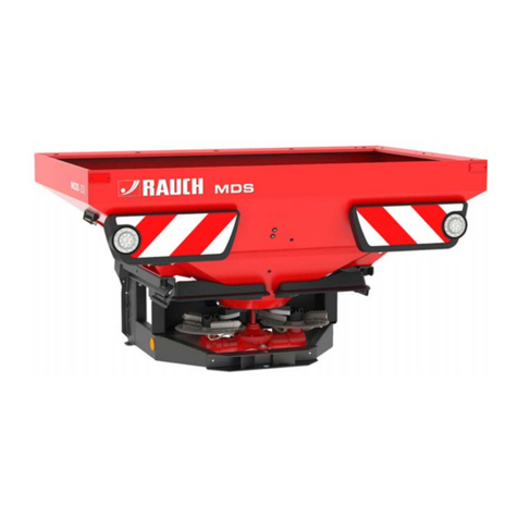
Rauch
Rauch MDS 8.2 instruction manual

HYDRA-PULL
HYDRA-PULL HP 700 Operation and parts manual

Vink
Vink Spreader quick start guide


