The Andersons DI2020 User manual
Professional 75lb Dual Impeller
Broadcast Spreader
MODEL #DI2020 ASSEMBLY INSTRUCTIONS
P80000_M52098_Rev_June2020
Professional 75lb Dual Impeller
Broadcast Spreader
MODEL #DI2020 ASSEMBLY INSTRUCTIONS
PAGE 1
Thank you!
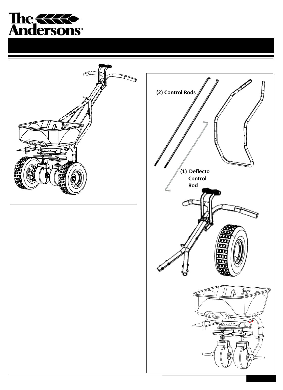
IN THE BOX
You have purchased the highest quality professional
broadcast spreader on the market. Featuring an
advanced design duel impeller system. This spreader
provides a symmetrical spread pattern, eliminating the
potential for uneven application. The dual impeller design
provides superior flexibility in spreading a variety of
granule types and seeds. A single adjustment of the rate
plate is all that is required to deliver a uniform application
each time.
While your spreader is mostly assembled, to minimize
shipping costs, you will need to attach the tires, frame
rest, upper handle, and control rods.
Before you begin, you will need the following tools to
assemble your DI2020 spreader:
Two 7/16” box wrenches,
One 1/2”
One 3/8” box wrench
(2) Control Rods
Helpful Hints
(1) Deflector
Control
Rod
(2) Tires
P15043
(1) Frame Rest
79008
(1) Upper Handle
Assembly
60368
(1) Hopper
Frame
Assembly
Other Items:
(1) Rain cover
(1) Hopper screen
(1) Hardware pack
The hardware kit include additional spare hardware:
-Cotter pin (for retaining tire)
-(2) 2 ¼” stainless bolts
-(2) ¼” stainless nuts
P80000_M52098_Rev_June2020
ASSEMBLY & OPERATIONS MANUAL
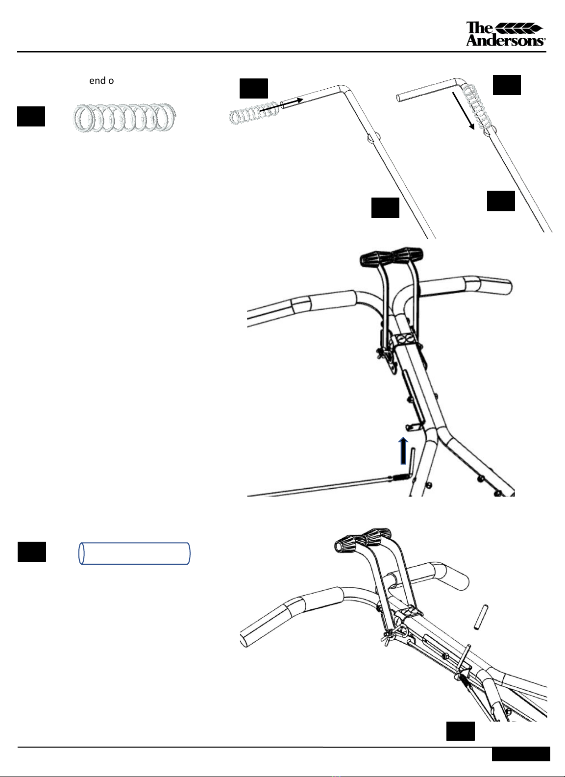
STEP 1: Remove from the box and set aside the
hardware pack containing control rods, deflector rod,
and calibrator keys. Also remove the wheel, hopper
cover, and screen.
STEP 2: Remove all inserts from the box to release the
hopper and frame assembly.
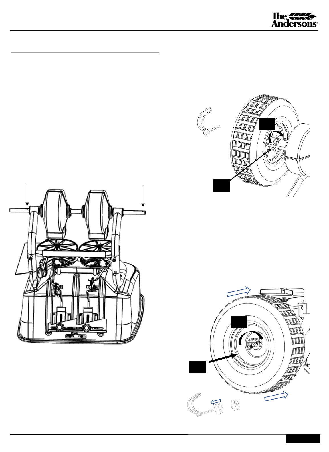
PAGE 2
ASSEMBLY: 20 minutes
STEP 3: Lift the hopper frame assembly out of the
box and place on level surface. Remove the
second wheel from the box and set aside. Place
the hopper on a level surface in the following
orientation. Notice the holes in the axle. One is
inboard and one is in an outboard location to the
centerline of the spreader.
(A) Inboard (B) Outboard
Locate two quick release tire clips from the
hardware bag. Orient both tires with the longer
portion of the hub facing inward.
4.1
4.2
Spring clip
STEP 4: Start with the inboard (A) tire and insert
(4.1) the wheel spring clip through the hole of the
orange rim, through the axle, and then flip (4.2)
the spring clip over the axle.
STEP 5: Move to the outboard (B) tire. Slide the
tire on the axle and install one spacer on the wheel
spring clip (5.1). Then put the spring clip through
the axle hole on the outside of the orange rim.
Install a second spacer on the wheel spring clip and
flip (5.2) the clip over the axle as shown below .
Push rim inward while inserting spring clip through
the axle. The tire should rotate freely.
5.1
5.2
Spring clip
& spacers
P80000_M52098_Rev_June2020
ASSEMBLY & OPERATIONS MANUAL
PAGE 3
ASSEMBLY: continued
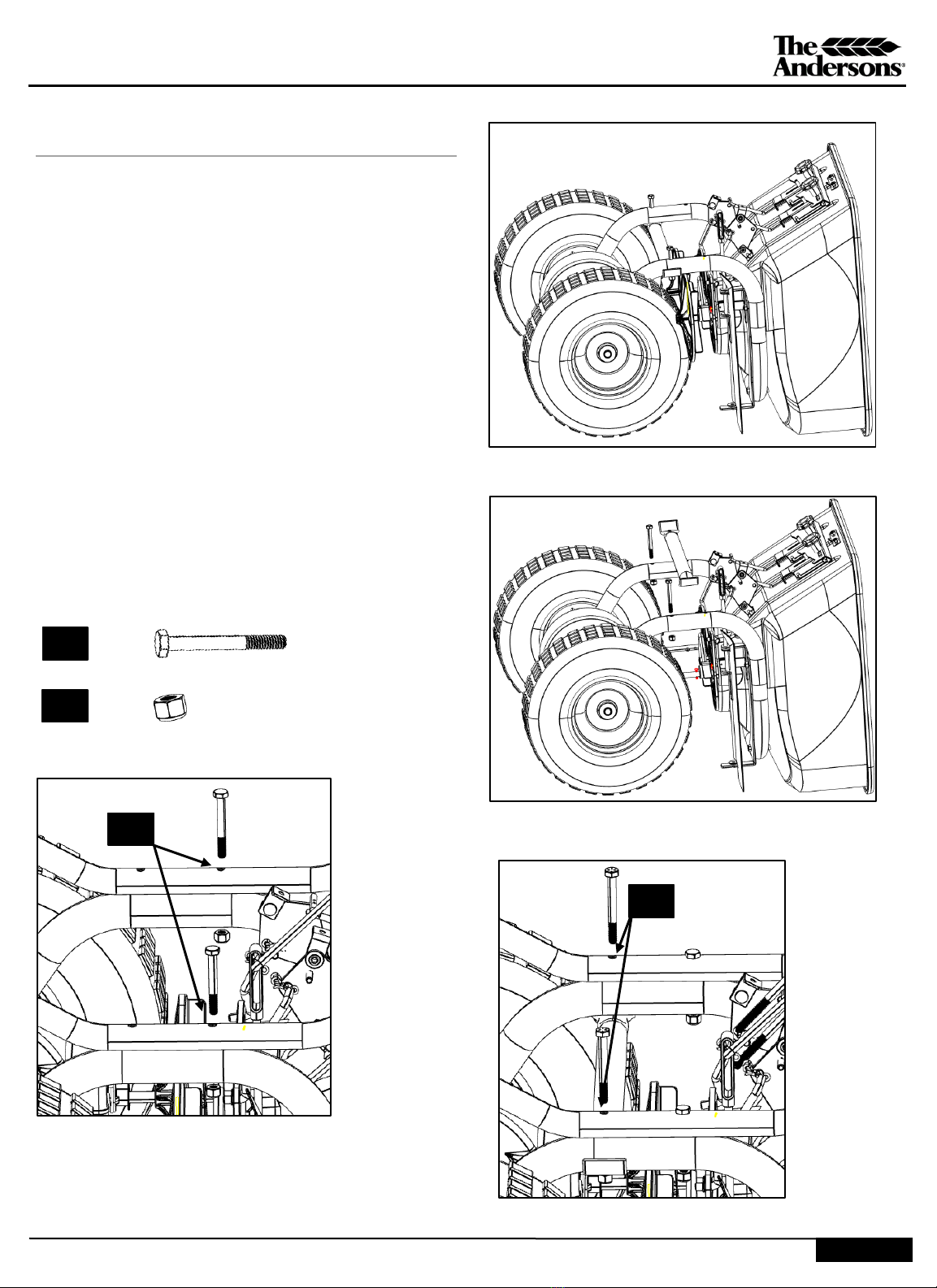
STEP 6: Position the spreader laying forward on
wheels and hopper as shown in Figure 6.3.
Figure 6.4 -Remove the cross brace by removing
two bolts and lock nuts. Keep the hardware for
reinstallation in step 6.6.
Figure 6.5 -Attach the lower frame rest to the
hopper assembly utilizing the two top holes. Two
(6.1) 1/4”x 2-1/4” bolts and two 1/4-20 nylon lock
nuts (6.2) are needed to make the assembly.
Install but do not tighten the lock nuts until next
step.
Figure 6.6 –Complete the rest assembly by
utilizing the two bottom holes. Reinsert the two
1/4”x 2-1/4” bolts that were removed in step 6.4
through the rest, then the frame, then the cross
brace. Install two 1/4-20 nylon lock nuts (6.2) and
now tighten all four lock nuts.
Figure 6.4 –Remove cross brace by removing 2 bolts and
lock nuts
6.1
6.2
4 x
4 x
Figure 6.3 -Starting Position –Attach Rest to Frame
Figure 6.5 –insert bolts and loosely tighten lock
nuts
6.2
Figure 6.6 –insert brace and tighten bottom lock nuts
6.2
P80000_M52098_Rev_June2020
ASSEMBLY & OPERATIONS MANUAL
PAGE 4
ASSEMBLY: 20 minutes
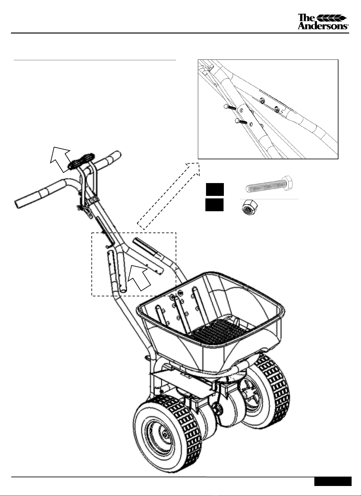
STEP 7: Position the spreader upright on wheels.
Place handles inside of the rest as shown in the
outlined box below and pull upward to mate the
handle in place with the rest.
Attach the upper handle to the frame rest installed
in Step 6 using four (7.1) 1/4” x 1 ½” hex bolts and
four 1/4” nuts (7.2). See closeup Figure 7.3
Upper handle to frame rest -Figure 7.3
7.1
7.2
4 x
4 x

P80000_M52098_Rev_June2020
ASSEMBLY & OPERATIONS MANUAL
ASSEMBLY: 20 minutes
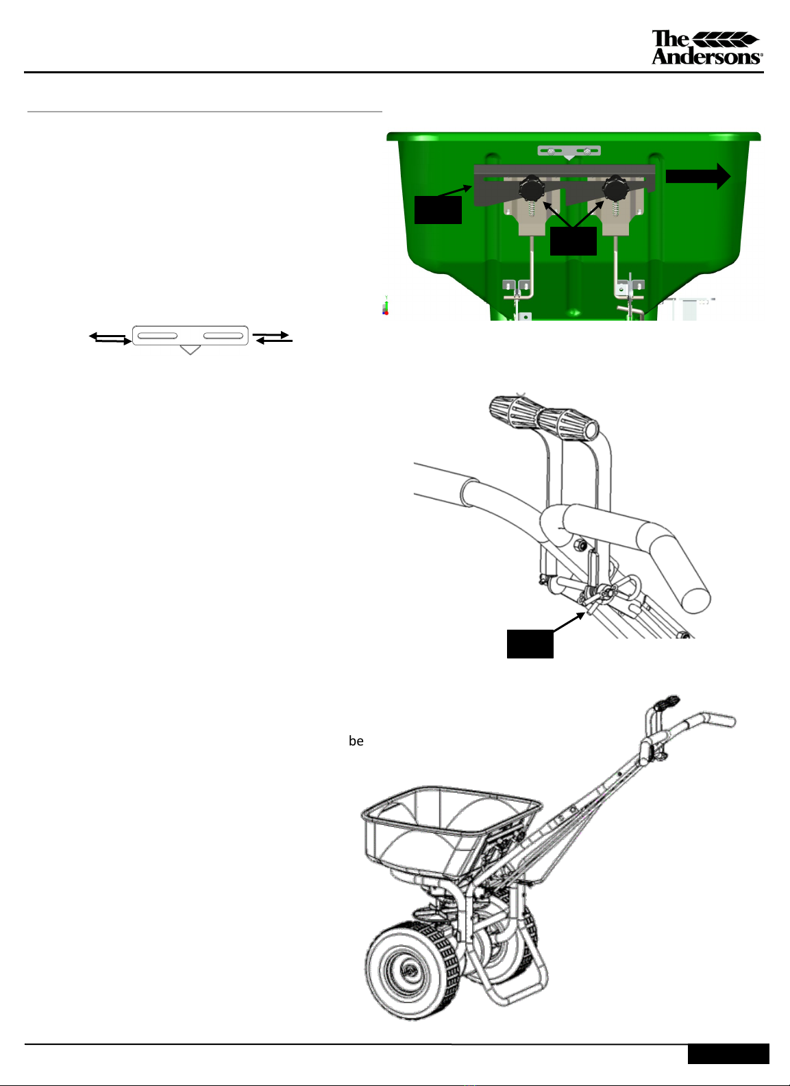
STEP 8.1: Attach control rods to spreader shut off
pivots. Install one 5/16” hex nut (8.1) on each
control rod as close as possible, to the halfway point
of the threaded portion. Look at the rods and make
sure the initial nut is threaded equally up the rod,
this is to give you a clean starting point for
calibration.
Insert control rods into pivot assembly. Note the
position of the 90 Degree brackets at 8.1. The
brackets must be in an upright position. Once the
control rods are inserted, place the remaining two
5/16” hex nuts (8.1) on the bottom of the control
rod. Finger-tighten these nuts in place, they will be
adjusted during calibration.
See CALIBRATION section at the end of these
assembly instructions. See Figure 8.3 for close-up
drawing.
.
8.2
8.1 4 x
2 x
STEP 8.2 -Insert the curved end of control
rods through the shut off handle levers and
secure with the two infinity spring clips
(8.2). See Figure 8.4 for close-up.
Figure 8.3 –attach control
rods at bottom
8.1
8.1
Attach control rods to shut off pivots-Figure 8.4
8.2
8.2
PAGE 5
Thread up, opening
shut off
Thread down, closing
shut off
P80000_M52098_Rev_June2020
ASSEMBLY & OPERATIONS MANUAL
PAGE 6
STEP 9: Install the 2” long deflector spring (9.1)
onto the coined end of the deflector control rod
(9.2).
9.1
9.3
1 x
1 x
9.2
9.1
9.2
9.1
Place deflector control rod grip (9.3) on the
top end of the deflector control rod.
Insert deflector control rod through the
bottom of the bracket mounted on upper
handle assembly.
9.3
P80000_M52098_Rev_June2020
ASSEMBLY & OPERATIONS MANUAL
PAGE 7
STEP 9 <continued> Insert lower portion of
deflector control rod through the metal slot
attached to deflector shield. With deflector in
the raised position, insert the deflector control
rod from outboard position towards the
inboard position and through metal loop.
Secure rod with infinity spring clip (9.4).
1 x
9.4
9.4
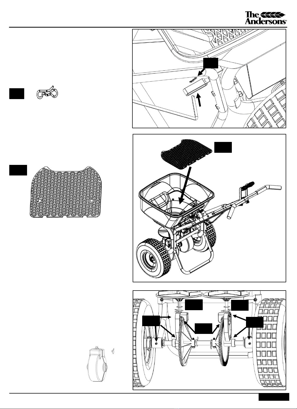
STEP 10: Place screen inside of the hopper so that
the cutouts align with hoppers interior shape.
10.1
STEP 11: Place hopper rain cover on the unit.
STEP 12: Remove the four gear box cover halves.
Using a grease gun, lightly lubricate grease fittings
12.1 on the axle bearing housings and gear carrier.
The bearings are already lubricated from the
factory so there is no need to put more than 1
handle pump into the fitting. Do not overfill. Apply
a small (less is more) amount of grease to the gear
teeth 12.2.
Re-install the four gearbox cover halves and secure
with the three retainer clips 12.3.
12.1 12.1
12.3
12.2
12.3
10.1
18126
3x
The unit was shipped with this spare hardware:
-Cotter pin (for retaining tire)
-(2) 2 ¼” stainless bolts
-(2) ¼” stainless nuts
P80000_M52098_Rev_June2020
ASSEMBLY & OPERATIONS MANUAL
PAGE 8
CALIBRATION: 10 minutes
STEP 13: Your spreader should be calibrated before first
use. Once complete, the spreader should not need
further calibration unless the spreader is disassembled
or damaged.
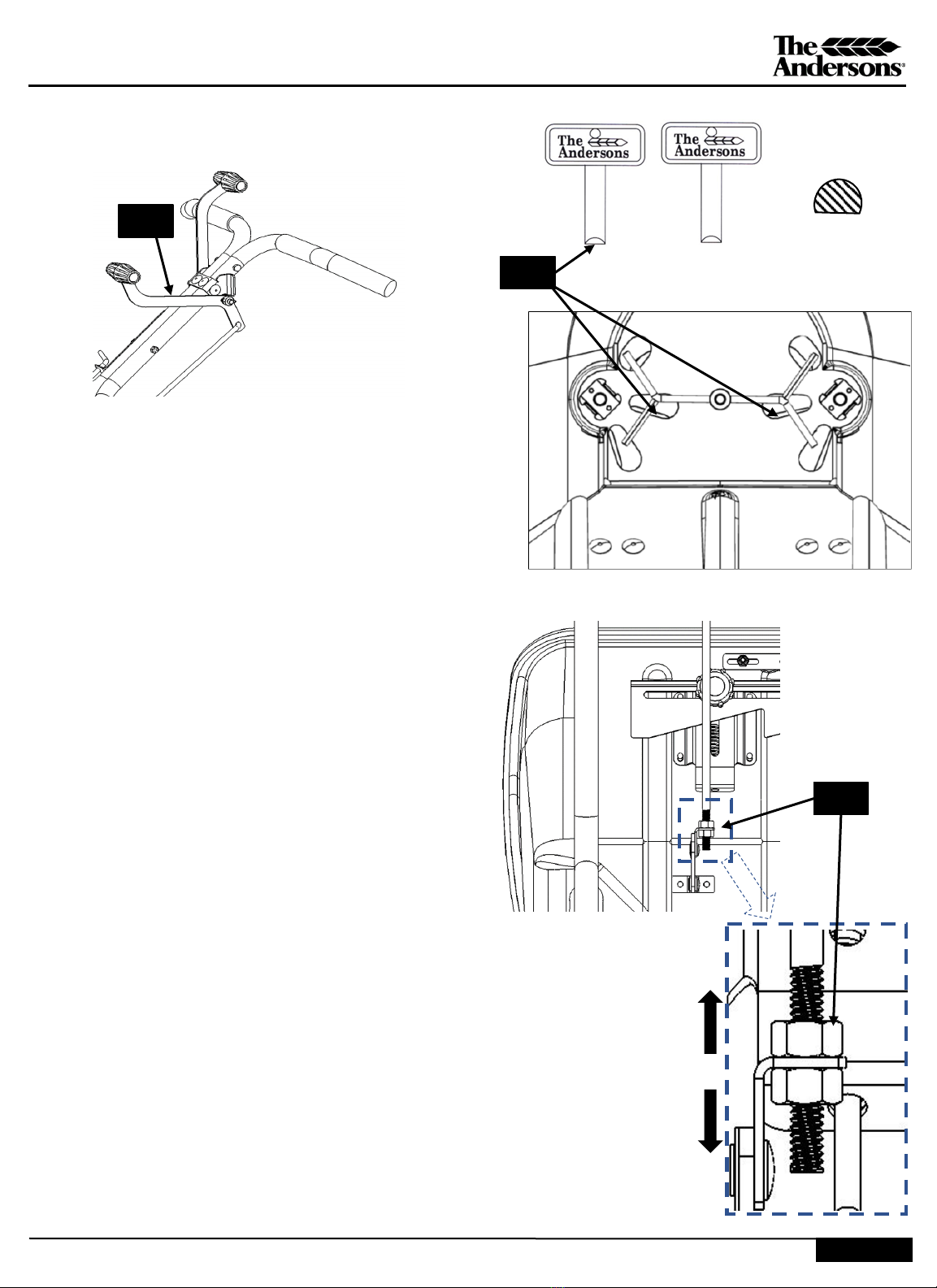
STEP 13.1: If the pointer is not set at setting “I”, pull
both shut off handles back to the closed position.
Loosen the rate plate knobs (13.2). Slide the (13.1) rate
control plate to the right until you reach the “I” setting.
Tighten the rate plate knobs (13.2).
13.1
13.2
STEP 14: Remove the lever tether pin (14.1) so that
the handles move independently. Each side is to be
calibrated individually. For this process, it is best to:
•Have your unit on the ground in an upright
position
•Keep your tools located close so you can reach
them while manipulating the controls
Tools Required:
o3/8” Wrench (nut on the rate indicator)
oPhillips screwdriver (Screw for rate
indicator)
o1/2” Wrench (nut on the control rod)
•Kneel next to the unit, to one side of the unit, so
the handle is to your dominate side
•This is the approach for a right-handed person
•This gives you easy access to both areas you will be
manipulating for this step
14.1
A B C D E F G H I J K L M N O P
P80000_M52098_Rev_June2020
ASSEMBLY & OPERATIONS MANUAL
PAGE 9
STEP 15: Start with left hand lever. Push the lever forward to
“open” position. See Image (15.1) below. Verify the opening
size using one of your calibration keys shown in image (15.2).
YOUR KEY WIL GO DIRECTLY INBOARD OF THE AGITATOR
(15.2). The FLAT portion of the key should be facing the
handlebars.
Flat side towards
handlebars
Key cross section
15.1
15.2
•If the key will not fit, that shutoff will need adjusted to
be more open.
•If the key is not contacting both sides, that side will
need adjusted to be more closed. (see threading detail
at right).
STEP 16: To adjust shutoff for BASELINE calibration:
Tool required: two 1/2” wrenches
•Push that lever forward to the open position
and loosen the nuts (16.1)
•Thread the nuts (both) in the same direction
needed. Making many small adjustments is
much more effective than making fewer big
adjustments until you are satisfied with the fit
of the calibration key.
•Tighten each nut (16.1) against the shut off
pivot
•Repeat this process for the other side.
Now that you have completed the baseline adjustment for
both sides, recheck the unit to fine-tune the calibration.
The next step will fine tune the spreader to reach the final
accuracy for maximum performance. Thread up, opening
shut off
Thread down, closing
shut off
16.1

P80000_M52098_Rev_June2020
ASSEMBLY & OPERATIONS MANUAL
PAGE 10
Thread up, opening
shut off
Thread down, closing
shut off
STEP 17: FINE TUNE CALIBRATION
Start by pushing both control levers forward and re-
inserting the calibration key(s) into the hole locations to
check the opening size. If both keys on both sides fit snug,
your spreader is fully calibrated.
If the key will not fit, that side will need adjusted to be
more open. If the key is not contacting both sides, that side
will need adjusted to be more closed. (see threading
detail). To adjust:
•Push that lever forward to the open position
and loosen the control lever nuts (16.1)
•Thread the nuts (both) in the same direction
needed. Making many small adjustments is
much more effective than making fewer big
adjustments until you are satisfied with the fit
of the calibration key.
•Repeat this for the other side.
If you are still having difficulty, contact us.
Congratulations, your spreader is now calibrated and ready
for operation. Re-insert the lever tether pin (Step 14).
16.1
OPERATION:
1) Check product bag for the desired rate setting and
swath width. The DI2020 uses the same rate setting
letter as the following Anderson models:
LCO-1000
AP 2000 & SR 2000
The DI2020 has a 12” wider effective swath width
than listed for the Anderson models. The rate
setting is achieved by loosening the rate control
knob and sliding the rate control plate until the
pointer aligns with desired letter.
1) When filling the hopper, make sure both operating
handles are in the closed position. Inserted in the
operating handles is a spring clip which allows for
independent use of each lever when removed.
2) Begin pushing the spreader forward before
engaging the levers to the desired open position;
close both levers prior to stopping.
3) When spreading material, a 3 MPH (brisk walk) is
recommended for even coverage. The hopper
should be level to the ground when in motion.
Tipping the spreader hopper too far forward or
backward may result in uneven product application
4) The settings on the product label are only
recommended starting points for calculating
product application rate. Test rate and effective
swath width on a small area prior to treating
desired turf area. Actual application rate can vary
depending on walking speed, wind, spread
material condition, and spreader condition.
5) The deflector shield is used to block off fertilizer
particles from the right portion of the swath width.
Use of the deflector shield is vital when applying
product near surfaces such as roads, driveways, etc.
When ready to apply, flip the side deflector shield
into the down position and remove lever tether pin
for independent lever operation. When the
deflector is in use, you will only use the left lever
while keeping the right one in the closed position.
P80000_M52098_Rev_June2020
PARTS LIST
CUSTOMER SERVICE
ONE YEAR WARRANTY
PAGE 11
The Andersons warrants to Purchaser the following:
1. Product will be free of defects in materials and workmanship for a period of one year from date of purchase.
2. The axle gear, gear support, pinion gear, axle, and axle bearings have a limited lifetime warranty to be free of defects in
materials and workmanship.
3. If the spreader is used for commercial rental the Limited Warranty shall be limited to a period of 90 days.
4. All unit and part replacement will be performed at the reasonable discretion of The Andersons.
5. Labor charges are not covered, and the unit need not be returned to the dealer for warranty service.
6. Proof of purchase must be supplied to The Andersons.
7. For warranty questions, contact Andersons at 1-800-225-2639.
The Andersons sole obligation under this warranty is limited to repairing or replacing the defective part.
This warranty does not extend to any Product or parts thereof that have been allowed to corrode, subjected to misuse, neglect,
accident, or modification by anyone other than The Andersons or that have been affixed to any nonstandard accessory attachment
or that have been used, stored, installed, maintained operated in violation of The Andersons instructions or standard industry
practice. No agent, employee or representative of The Andersons has any authority to bind The Andersons to any affirmation,
representation or warranty concerning the Product and any affirmation, representation or warranty made by any agent, employee
or representative shall not be enforceable by Purchaser.
THIS WARRANTY EXTENDS ONLY TO THE ORIGINAL PURCHASER AND IS EXPRESSLY IN LIEU OF ANY OTHER EXPRESS OR IMPLIED
WARRANTIES, INCLUDING WITHOUT LIMITATION ANY IMPLIED WARRANTY OR MERCHANTABILITY OR FITNESS OR INTENDED
USE FOR A PARTICULAR PURPOSE AND OF ANY OTHER OBLIGATION ON THE PART OF The Andersons. The Andersons SHALL NOT
BE LIABLE FOR ANY INCIDENTAL, SPECIAL OR CONSEQUENTIAL LOSS, DAMAGE OR EXPENSE DIRECTLY OR INDIRECTLY ARISING
FROM THE USE OF ANY OF THE PRODUCT INCLUDING, BUT NOT LIMITED TO, DAMAGE OR LOSS OF OTHER PROPERTY OR
EQUIPMENT, LOSS OF PROFITS OR REVENUE, COST OF CAPITAL, COST OF PURCHASED OR REPLACEMENT GOODS, OR CLAIMS OF
CUSTOMERS OF PURCHASER.
1-800-225-2639 | www.andersonsturf.com | help@andersonsplantnutrient.com
The Andersons Inc, 1947 Briarfield Blvd, Maumee, OH 43537
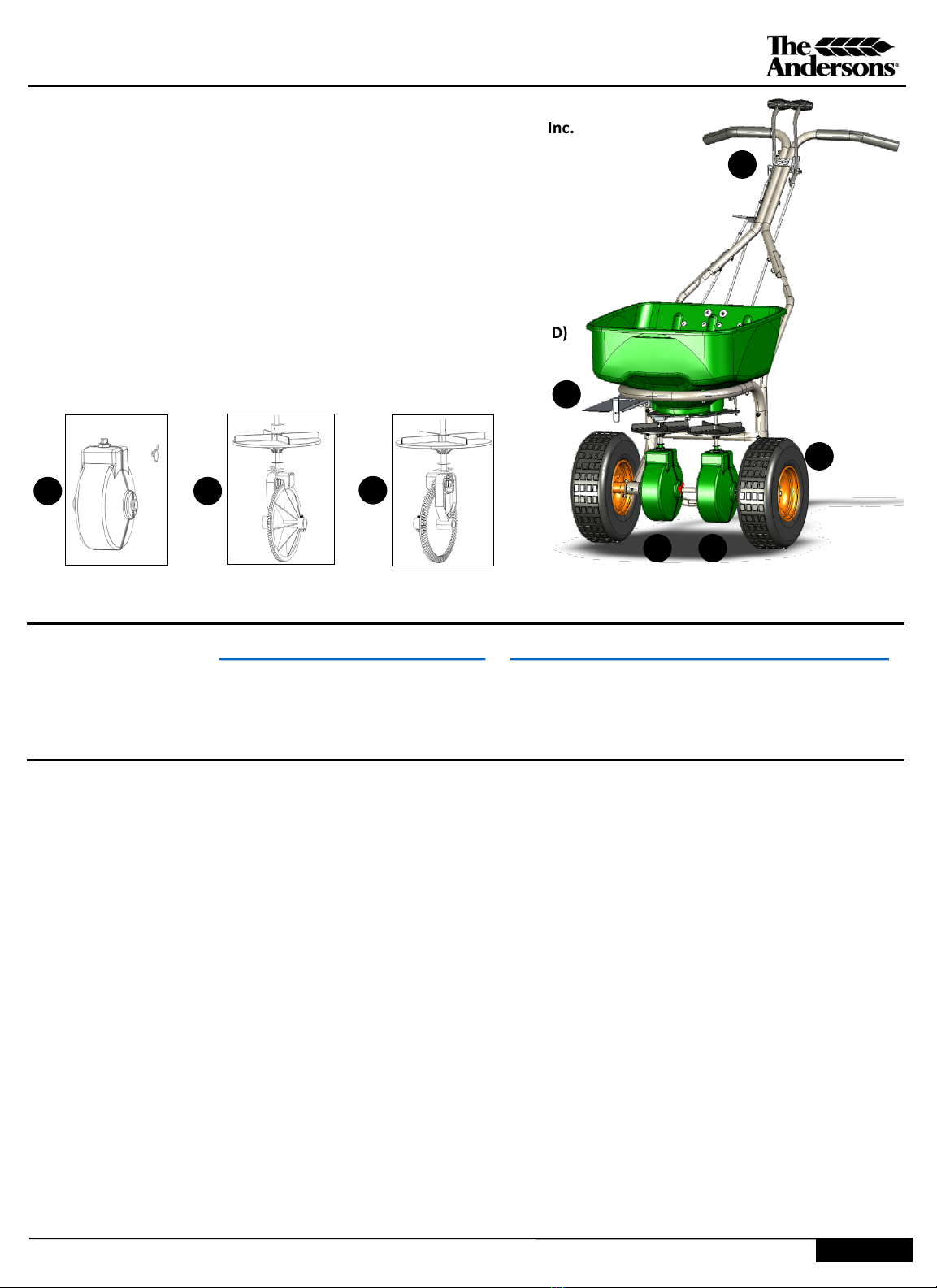
1. P790161LG ANDERSONS RAIN COVER
2. 18126 GRATE / HOPPER SCREEN
3. P1000060 STAINLESS STEEL DEFLECTOR KIT
4. P15043 TIRE WHEEL & ORANGE RIM
5. 78003 GEAR COVER KIT
6. 78002 IMPELLER, GEAR, CAM & PINION ASSEMBLY
7. 78001 IMPELLER, GEAR, & PINION ASSEMBLY
8. 60368 UPPER HANDLE ASSEMBLY
9. 60262 HARDWARE PACK (CONTROL RODS, BOLTS, SPRING
CLIPS, LOCK NUTS, CALIBRATION KEYS, DEFLECTOR ROD)
10. 60336 ANDERSONS GREEN HOPPER
11. 79008 FRAME -REST
12. 79006 FRAME –HOPPER & AXLE
For replacement parts, call 574.848.7491
Service parts for Andersons spreaders are sold by EarthWay Products, Inc.
6 7
4
3
8
5 6 7
3x
Table of contents
Other The Andersons Spreader manuals


Popular Spreader manuals by other brands


Fimco
Fimco MS-25BU owner's manual

Art's Way
Art's Way X350 Operator manual & illustrated parts list

Shindaiwa
Shindaiwa RS76 owner's manual

H&S
H&S 5134 Operator's manual

Precision Products
Precision Products SB4300RD Parts list and instructions

Buyers Products Company
Buyers Products Company TGS01B installation instructions