PGI RFG-14M Instruction Manual

Approved
RFG-14M Polidek OG Russian Federation
LLC ‘PGI’
HYDRAULIC
FLANGE SPREADER
RFG-14MPolidek
OPERATING GUIDELINES
(WITH CERTIFICATE)

RFG-14M Polidek OG p. 2
OPERATING GUIDELINES
These operating guidelines merged with a certificate are for the hydraulic flange spreader
of the RFG-14C Polidek series. They contain technical description of the tool, guidelines for
correct and safe operation and specifications.
The manufacturer reserves the right of introducing minor changes and improvement into the
tool design that are not shown in the present operating guidelines.
PURPOSE AND SCOPE
The spreader is aimed at flange spreading while replacing gaskets, mounting caps,
replacing taps and valves on heat plants, sanitary and technical systems, oil and gas pipelines,
etc.
The spreader operates at environment temperatures from -30 to +40oC.
The designation: RFG-14M Polidek, where RFG-14M Polidek stands for hydraulic flange
spreader; 14 –nominal spreading force value, tf.: C –standard set.
MAIN SPECIFICATIONS
1. Spreading force –14.5 tf
2. Minimal gap –6 mm
3. First step spacing interval - 15 mm
4. First step maximal spreading force –14.5 tf
5. Spreading width with usage of step blocks –94 mm*
6. Operating pressure –70 MPa
7. Operating liquid - oils with 13.5-16.5 cS viscosity at temperature of +40o C
8. Coating of wedge operating parts and side plates (to reduce dragging and prevent from
tearing and corrosion)
9. RFG14 weight (without step blocks) –7 kg
10. - at Customer’s option spreading width value may be enlarged
LIST OF EQUIPMENT
1. RFG-14 Wedge head –2 pc.
2. Hand-operated hydraulic pump. Operating pressure = 70 MPa –1 pc.
3. High-pressure hose –3 pc.
4. Safety unit –2 pc.
5. Step blocks –4 pc.
6. Screw –4 pc.
7. Allen wrench –2 pc.
RFG-14M Polidek OG p.3
8. Operating guidelines (with certificate) –1 pc.
9. Case –2 pc.
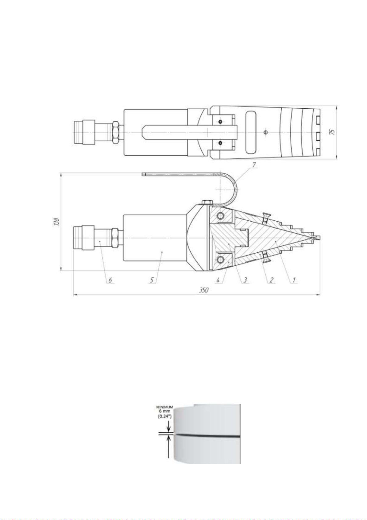
SPREADER STRUCTURE
The RFG-14 Polidek spreader structure is shown in the Figure 1
Fig.1
1 - wedge; 2 –side plate; 3 –lock; 4 –body; 5 –hydraulic cylinder assembly; 6 –Q/C half
coupling; 7- handle;
OPERATING PRINCIPLE
1. Define the actual gap between flanges –the minimal gap of 6 mm is required for
spreading (Fig. 2).
(Fig.2)
RFG-14M Polidek OG p.4
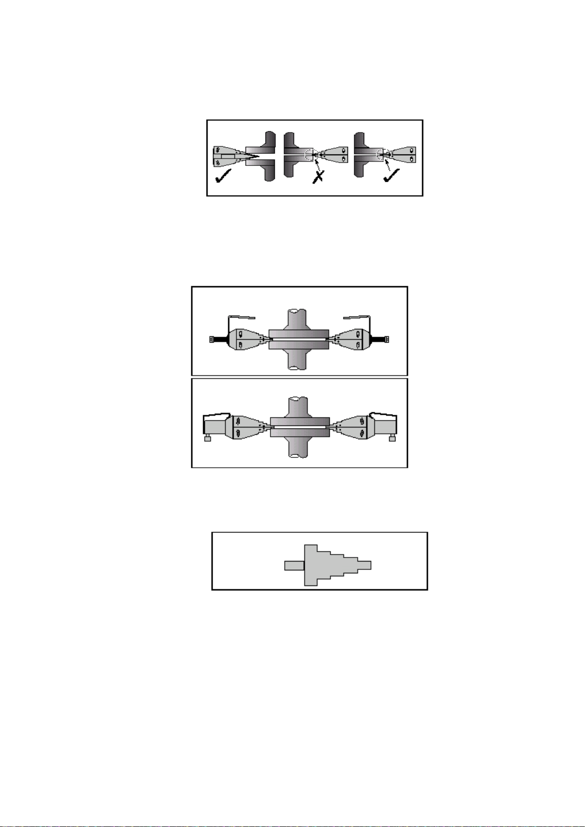
2. Introduce the wedge head in the gap between flanges until the vertical side of the stop
interacts the flange outer surface (Fig. 3a).
(Fig.3а)
Make sure that the whole step surface is used.
We strongly recommend to use two tools for spreading the gap between flanges that should
be mounted at an angle of 180 degrees to each other (Fig.3b)
Fig.3b
3. Introduce a safety unit into the gap and shift load on it after spreading flanges to desired
depth or the maximal spreading value for the given step block (Fig. 4).
Fig.4
4. For further spreading of flanges introduce the wedge head into the gap between flanges and
use the next step of the wedge head.
RFG-14M Polidek OG p.5
1. Maximal opening of the flange spreader may be enlarged when it is used together with an
additional step block (see Fig. 5).
2. The wedge is returned to its initial position by relieving pressure with the screw 8 (Fig. 1)
situated on the body of the hydraulic cylinder.
3. Clean the spreader from contaminants and place it in the case when the work is finished.
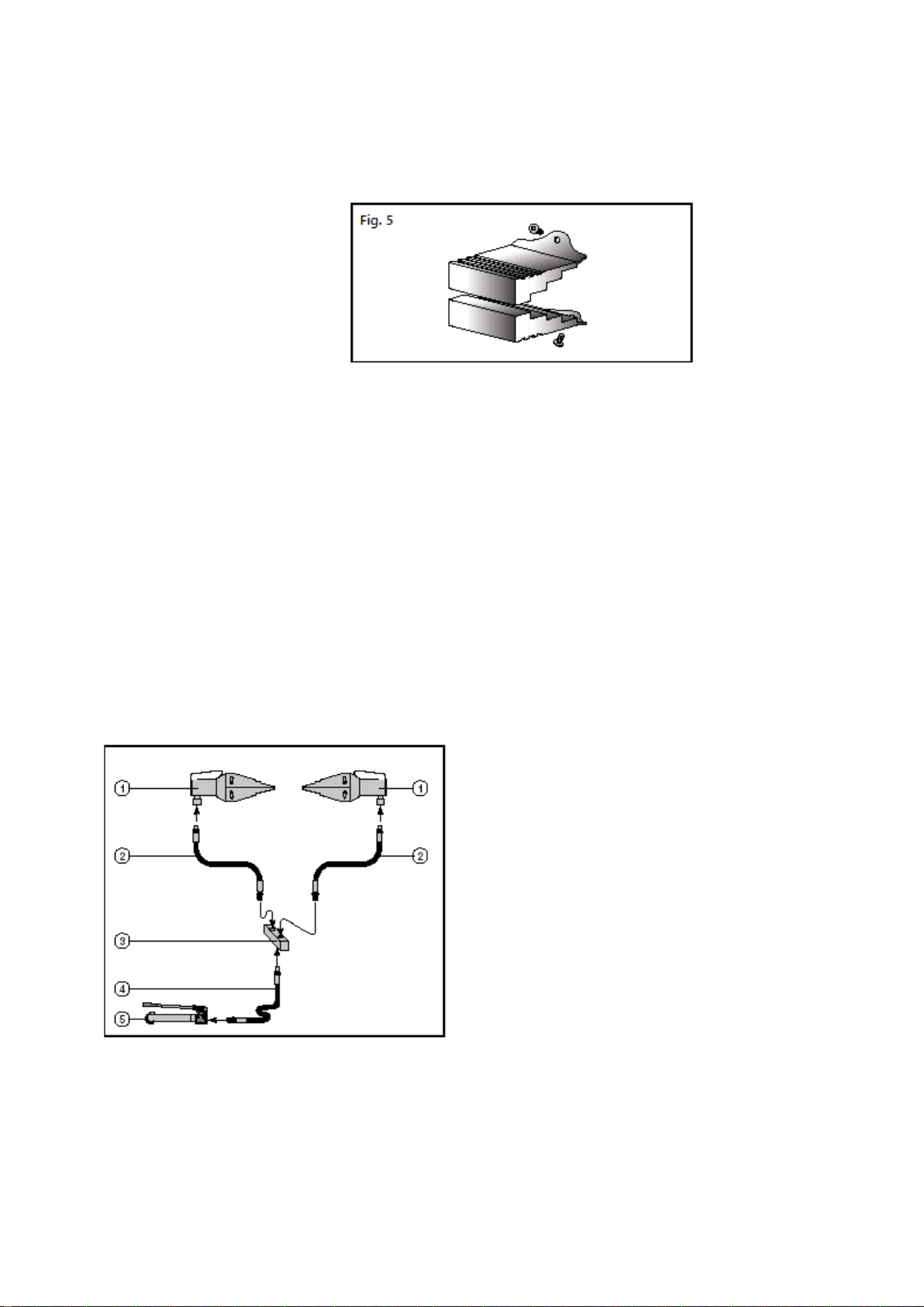
CO-UTILIZATION OF WEDGE MECHANISMS
Co-utilization of two hydraulic wedges allows to achieve even flange spreading. Wedges should
form a flat angle (180°) in relation to flanges circumference.
Two hydraulic wedges can be used concurrently in combination with a hand-operated pump, a
double-flow collector and a hydraulic hose (see Fig.
6)
1 –RFG-14 Polidek wedge
2, 4 –Hydraulic high-pressure hoses
3 –Double-flow collector
4 –Hand-operated hydraulic pump
(pressure 70 МPa; volume 1 l.)
Fig.6

RFG-14СPolidek OG p. 6
SAFETY PRECAUTIONS
Safety requirements and measures protecting staff from possible effects of
dangerous factors should be observed during flange spreader operation.
The spreader should be operated with observance of all fire safety requirements.
.
It s forbidden to do the following:
operate the flange spreader at forces exceeding the nominal one stated in the ‘Main
Specifications’ part;
operate the flange spreader with usage of hydraulic liquids of unknown brands and the
liquid purity grade, mix liquid of different brands;
operate the flange spreader in conditions of strong contamination (dust, dirt, sand, etc.)
without additional protective measures for the tool;
relieve pressure in the hydraulic system abruptly that can cause hydraulic shocks; start
operation without having preliminarily removed air from the hydraulic system;
operate the flange spreader if there are leaks in joints, screw joints as well as if the pump,
high-pressure hoses or other elements of the hydraulic system are not operable;
retorque joints or disconnect the high-pressure hose when there is pressure in the
hydraulic system;
bend high-pressure hoses;
act mechanically upon wedge heads under pressure;
operate the flange spreader by uneducated staff members.
PREPARING TOOL TO OPERATION
To prepare the spreader to operation:
Remove it from storage according to requirements of GOST 9.014.
Connect the RFG14 Polidek cylinder to the hydraulic pump through the high-pressure
hose. To do that:
remove gaps from quick connectors;
attach the half coupling of the high-pressure hose and the half coupling 6 of the cylinder
5 of RFG 14 Polidek (Fig. 1) and torque the joint with a help of the half coupling acorn
nut against stop fingertight. Do not use any special tools. Connect the hydraulic pump to
the high-pressure hose. Torque joints with a help of a wrench.
Remove air from the hydraulic system assembled this way.
To do that:
open the pressure supply valve of the hydraulic pump;
supplying hydraulic liquid with a help of the pump, spread RFG14 Polidek,
relieve pressure and return RFG14 Polidek to its initial position. Repeat 2-3 times.
Smooth even motion of RFG14 Polidek rods indicates absence of air in the hydraulic
system.

RFG-14M Polidek OG p.7
Use oils stated in the ‘Main Specifications’ part and also other oils with 13.5-16.5 cS
viscosity at temperature of +40oC.
If there is a leak of hydraulic liquid in joints of quick connector half couplings, replace
gaskets of quick connectors.
OPERATION PROCEDURE
The operating place should be clean and free from foreign objects.
Only directly involved into the operation staff members can be present in the operating
place. Those members who have not got through the occupational safety and health
instruction and training on spreader operating rules are not admitted to operation.
Mount the spreader on the operating place. To do that:
Place the spreader wedge head into the gap between flanges until the vertical side of the
side plates step 2 (Fig.1) of RFG14 Polidek interacts the flange outer surface (Fig. 3).
Spread flanges to desired depth or the maximal spreading value for the given step by
supplying pressure, then place the safety unit into the gap and shift load on it (Fig. 4).
Introduce the wedge head into the gap between flanges and use the next step of wedge
heads for further flange spreading. For maximal flange spreading mount the step block
(Fig. 5). Pressure in the spreader is relieved with a help of the valve on the hand-
operated hydraulic pump.
When the work is finished, disconnect the hose from RFG 14 Polidek, place protective caps on
half couplings of quick connectors, clean the spreader from contaminants; place the wedge head
in the case.
TECHNICAL MAINTENANCE
Technical maintenance is required to keep the spreader operable. To do that, it is required to do
occasionally the following:
1. Clean the spreader from contaminants.
2. Check quality of ball joints.
3. Lubricate spreader dragging surfaces with the Molykote lubricant with molybdenum
disulfide regularly.
4. In case of long-term intervals in operation of more than 4 months, prepare the tool for
storage in the following order:
- clean the tool from contaminants;
- wipe dry; cover outer surfaces of the tool with storage lubricant.
Store in closed unheated space where air humidity does not exceed 70%.

RFG-14M Polidek OG p. 8
STORAGE REGULATIONS
1. Short-term storage.
A period of short-term storage is no more than 1 year:
- store in closed unheated space; prepare to storage.
2. Long-term storage.
A period of long-term storage is no more than 3 years.
Conditions of long-term storage:
- prepare the tool for storage, place in a box;
- store in closed unheated space.

WARRANTY LIABILITIES
The manufacturing plant guarantees tool compliance with requirements of statutory and
technical documents and its operability if operating and storage conditions stated in the operating
guidelines are observed.
Warranty period –18 months from a delivery date.
Warranty liabilities are not discharged if a customer was disassembling and repairing the tool
without help and permission of the manufacturer, and if there are no filled columns and stamps
on a warranty certificate.

WARRANTY CERTIFICATE
The hydraulic flange spreader RFG-14СPolidek model manufacturing number No.
_____________, was manufactured and packed according to requirements of statutory and
technical documents and conceded operable.
Delivery date «____» ______________________20___.
Packager______________________ / _________________________/
(signature) (print full name)
Warranty period of tool operation –18 months from the delivery date.
Complaints are to be sent at the following address:
LLC ‘PGI”
454106, Chelyabinsk, Ostrovkogo st., 62
Tel./fax: (351) 729-92-40
info@polidek.ru
www.polidekinternational.ru
Chief Executive Officer
LLC ‘PGI’
_______________ S. V. Kotin
official seal
Customer (enterprise name and address): __________________________________
_____________________________________________________________________________
_____________________________________________________________________________
Signature of an individual responsible for tool reception with a print full
name___________________
_____________________________________________________________________________
Reception date «___» __________________20___.
Table of contents
Popular Spreader manuals by other brands

National Instruments
National Instruments NI-9695 installation instructions

Magnum
Magnum V-BOX PV Series Installation and operating instruction manual

SCH
SCH SSS2 operating instructions

Faller
Faller Gras-Fix manual

Rauch
Rauch SA 250 Operator's manual

Brinly-Hardy
Brinly-Hardy Spyker Spreaders ROS 6 quick start guide

Rauch
Rauch AXEO 2.1 instruction manual

Brinly
Brinly P20-500BH owner's manual

Gardena
Gardena Comfort 500 Assembly instructions

The Handy
The Handy THS80 instruction manual

Broadwood
Broadwood Wessex Country FS170T Operations manual and parts book

Kugelmann Maschinenbau
Kugelmann Maschinenbau DUPLEX INOX operating instructions


