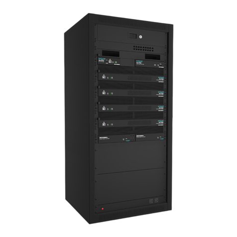
Bogen NQ-E7030 User manual

Analog Station Bridge
Configuration Guide
NQ-E7030
© 2018–2021 Bogen Communications, Inc.
All rights reserved.
740-00015G
211012

i
Contents
Contents . . . . . . . . . . . . . . . . . . . . . . . . . . . . . . . . . . . . . . . . . . . . . . . . . . . . . . . . . . . . . . i
Configuring the Analog Station Bridge . . . . . . . . . . . . . . . . . . . . . . . . . . . . . . . . . . . . 1
Using the Dashboard . . . . . . . . . . . . . . . . . . . . . . . . . . . . . . . . . . . . . . . . . . . . . . . . . . . . . . . .2
Updating Firmware . . . . . . . . . . . . . . . . . . . . . . . . . . . . . . . . . . . . . . . . . . . . . . . . . . . . . . . . . .6
Network Settings Tab Parameters . . . . . . . . . . . . . . . . . . . . . . . . . . . . . . . . . . . . . . . . . . . . .7
Configuration Settings Tab Parameters . . . . . . . . . . . . . . . . . . . . . . . . . . . . . . . . . . . . . . . . .9
Accessing Log Files . . . . . . . . . . . . . . . . . . . . . . . . . . . . . . . . . . . . . . . . . . . . . . . . . . . . . . . . .13

1
Configuring the Analog Station Bridge
The Nyquist Analog Station Bridge (ASB) allows the Nyquist solution to use the existing
analog call switch and speaker infrastructure when upgrading from Multicom 2000,
Quantum Multicom IP, and third-party intercom systems. When used exclusively as a net-
worked component of the Nyquist paging and intercom solution, the Nyquist ASB per-
mits a hybrid Internet Protocol (IP)/analog system configuration through use or
connection of analog 25V speakers and associated analog call switches (for example,
CA15C type). This ASB has 24 station connections that attach to wired speakers and their
associated call switches. While each connection has its own Session Initiation Protocol
(SIP)–addressable Station ID, the ASB itself uses a single network IP address.
The Nyquist server can automatically discover and configure the ASB, but you can also
manage the device, and manually configure some settings, through the ASB’s web-based
user interface (web UI).
A short press of the appliance’s Reset button reboots the device. If you press the Reset
button for 10 seconds, the appliance returns to the factory default configuration settings.
Returning to the default configuration settings does not change the appliance’s firmware.
The following sections describe settings and configurations that can be applied to this device
which are not controlled by the Nyquist server. For information about using Nyquist’s auto-
matic configuration process, refer to the Nyquist System Administrator Guide.
To access the appliance’s UI:
1Access the appliance’s web UI by doing one of the following:
a) On your web browser, enter the IP address for the appliance as the URL.
b) From the Nyquist web UI navigation bar, select Bridge Devices, then select the
Link icon to open the device web interface for the selected device.
c) From the Nyquist web UI navigation bar, select Stations, select Appliance Status,
navigate to the device that you want to configure, and then select the Link icon.
Note: Do not use third-party Chrome browser extensions with the Nyquist user interface.

2
2At the Nyquist Appliance - Login page, enter username and password, and then select
Login.
The dashboard for the selected appliance appears.
Using the Dashboard
The ASB dashboard displays information about the ASB, including LEDs and temperature
output that provides status of the ASB. You can also make temporary adjustments to the
ASB volume using a volume slider that appears at the bottom of the ASB dashboard. The
volume can be adjusted on a scale from -42 dB to 0 dB.
Figure 1. Nyquist Appliance Login

3
The dashboard displays the following fields:
Real-time statuses that can be viewed from the dashboard are described in the following
table:
Figure 2. Nyquist Analog Station Bridge Dashboard
Table 1. Appliance Dashboard Fields
Device Type Displays the model of this device.
Serial Number Displays the serial number for the device.
MAC Address Displays the Media Access Control (MAC) address, which
is a unique identifier assigned to network interfaces for
communications on the physical network segment.
Firmware Version Displays the firmware version installed on the station.

4
Table 2. ASB Status Indicators
Channel 1/2 Status Provides clipping status for Channel 1 and 2. Clipping is
sound distortion that occurs when an amplifier attempts
to deliver an output voltage or current that is beyond its
maximum capability. If this indicator is green, the channel
is not clipping. Red means the channel is clipping. Gray
means that the appliance’s web UI is not receiving data
from the appliance's web server, indicating that the ASB
may be offline or rebooting.
Protection Status Indicates if the ASB is in partial shutdown mode to protect
the built-in two-channel amplifier module.
In this case, the appliance itself may remain “on” as indi-
cated by its front panel Status and Power LEDs. However,
the ASB’s amplifier module senses various faults that can
be caused by factors such as incorrect speaker wiring (for
example, shorts or too low an impedance). These faults
can overload the amplifier output capability (overcurrent/
clipping) and/or amplifier thermal conditions (overheat-
ing).
If the indicator is green, the amplifier module is operating
in a normal capacity. If the indicator is red, the amplifier
module is in protection mode and audio will not be passed
to any ASB port. If the cause is temporary or intermittent
(for example, signal clipping), the amplifier module will
quickly return to normal mode.
If the system remains in protection mode for an extended
period of time, this likely indicates some sort of wiring
fault or low-impedance condition is present that must be
rectified.
When the indicator is gray, the ASB's web UI is not receiv-
ing protection status information from the appliance’s web
server. This usually indicates that the network connection
has been interrupted or dropped or that the device is
rebooting.

5
The following buttons are available at the top of all pages in the application.
Temperature Provides a snapshot of the amplifier module’s temperature
in degrees Celsius during any transition (that is, change
state) on the Channel 1, Channel 2, or Protection Status
indicators.
Note: The ASB’s UI displays the temperature reading from
the latest update; it does not receive or display continuous
real-time amplifier module temperature readings.
Volume Sets the volume for the speaker during an intercom call or
page. This is a temporary adjustment that allows the user
to experiment with the loudness of the speaker. To make
permanent adjustments, change the various cut level set-
tings on the Nyquist System Controller.
The value can be adjusted between -42 dB and 0 dB.
Table 3. Appliance Dashboard Buttons
Dashboard Displays the dashboard.
Configuration Settings Accesses the Configuration Settings page where you can
view and set various options or select to receive config-
uration settings from a Nyquist server.
Network Settings Accesses the Network Settings page where you can view
and set network settings, such as the static IP address.
Firmware Update Accesses the Firmware Update page where you can view
the current Nyquist version, update firmware to a new
version, restore the configuration to factory settings,
and reboot the appliance.
Logs Accesses log files, which record either events or mes-
sages that occur when software runs and are used when
troubleshooting the appliance.
Help Accesses the appliance’s online help.
Manual Displays the appliance’s configuration manual.
Logout Logs out of the appliance’s dashboard.
Table 2. ASB Status Indicators (Continued)

6
Updating Firmware
When you select Firmware Update from the appliance’s web UI, the Firmware Update
page appears. From this page you can determine which Nyquist firmware version the
appliance is using and if an update is available. You can also load a firmware release,
install the loaded firmware, restore the configuration to factory defaults, and reboot the
appliance.
To use the Firmware Update page:
1On the appliance web UI’s main page, select Firmware Update to view or update the
firmware version.
2If you already have a firmware file you would like to install to the appliance, select
Upload Firmware to upload the firmware file from your computer to the appliance. A
popup screen appears that allows you to select the file that you want to upload. You
can navigate to the file’s location. After you select the file, select Upload.
Note: A Nyquist appliance connected to the Nyquist network receives a configuration
file from the Nyquist server that includes the latest firmware available from the server.
If the firmware is different from the one installed on the appliance, an automatic firm-
ware update occurs unless the Firmware parameter for the station is left blank. Refer to
the Nyquist System Administrator Guide for more information.
Figure 3. Firmware Update Page

7
3The page displays the uploaded firmware version (“New Nyquist Version”) and an
Update Firmware button appears. Select this button if you want to update the appli-
ance’s firmware to the uploaded version.
4If you want to return your appliance to its original factory configuration, select
Restore Factory Settings.
5Select Reboot Appliance to restart your appliance.
Network Settings Tab Parameters
Network settings can be configured dynamically by the Nyquist server or manually by
using the appliance’s web UI.
To manually configure network settings:
1On the appliance web UI’s main page, select Network Settings.
2Select your desired network settings.
Table 4. Firmware Update settings
Current Nyquist Version Shows the version of the appliance’s currently
installed firmware.
New Nyquist Version Shows the version of the firmware that has been
loaded, though not installed, onto the appliance.
Update Firmware Available only when a new firmware version has
been loaded onto the appliance (as specified in
New Nyquist Version).
Installs the loaded firmware. A reboot may be
required after installation.
Upload Firmware Prompts the user to specify a firmware file, which
will then be loaded (though not installed) onto the
appliance.
Note: To obtain the firmware file for a specific ver-
sion, please contact Bogen Customer Service.
Restore Factory Settings Returns the appliance to its original factory con-
figuration.
Note: This does not install the original appliance
firmware. The firmware will not be changed.
Reboot Appliance Restarts the appliance.

8
3Select Save.
Network settings are described in the following table:
Figure 4, Network Settings
Table 5, Network Settings
IP Address Identifies the IP address assigned to the appliance.
Netmask Identifies the subnetwork subdivision of an IP net-
work.
Gateway Identifies the address, or route, for the default gate-
way.
VLAN ID Identifies the Virtual Local Area Network (VLAN) for
this appliance. Values range from 0 to 4094.
VLAN Priority Identifies the priority of the network traffic on the
VLAN. Priority can range from 0 through 7.
NTP Server Identifies the IP address or the domain name of the
Network Time Protocol (NTP) Server.

9
Configuration Settings Tab Parameters
The way to configure Nyquist appliances is to obtain configuration settings from the
Nyquist server.
TFTP Server Identifies the host name or IP address of the Trivial
File Transfer Protocol (TFTP) server.
The specified TFTP server can be used to automati-
cally set this device’s Configuration settings via the
Get Configuration from Server button.
If TFTP Server from DHCP (see below) is set to “Yes”,
this value will be auto-configured via DHCP option
66, assuming the DHCP server has been configured
to provide option 66. For details, see the documenta-
tion for your DHCP server.
Note: A TFTP server runs on the Nyquist server on
port 69 (the standard TFTP port) and the optional
Nyquist DHCP service automatically provides this
TFTP address via option 66.
If this value is unspecified, the TFTP Server from
DHCP will automatically be set to “Yes”, this field will
become read-only, and DHCP will be used to config-
ure this setting. To change this value, the TFTP Server
from DHCP setting must be set to No, which makes
the field editable.
TFTP Server from DHCP “Yes” means the device will use the DHCP option 66
value to retrieve an address for the TFTP Server from
DHCP.
“No” means the device will ignore the DHCP option
66 value and use the manually configured value of
the TFTP Server (see above).
DHCP Enabled Indicates if the device is enabled to use DHCP to
retrieve its IP configuration.
Reboot Appliance Indicates that this appliance should reboot when the
Save button is clicked.
Table 5, Network Settings (Continued)

10
To view the Nyquist appliance configuration:
1On the appliance Web UI’s main page, select Configuration Settings.
2View the configuration settings.
Figure 5. Configuration Settings for ASB
Table 6. Configuration Settings
Get Configuration from
Server
Retrieves configuration settings (i.e., web username,
server, and local port) from the TFTP server specified in
the Network Settings (see Table 1 on page 1).
Web Username Displays the web username for this appliance.
Emergency-All-Call Identifies the IP address, port number, cut level (vol-
ume), and station list used for emergency all-call pages.
All-Call Identifies the IP address, port number, cut level (vol-
ume), and station list used for all-call pages.
Audio Distribution Identifies the IP address, port number, cut level (vol-
ume), and station list used for audio distribution.

11
Digital Call Switch Management
You can assign digital call switches to ports on an ASB via the appliance’s Configuration
Settings tab. If an analog switch was configured as a station with a type of Digital Call
Switch & Speaker, it will also appear on the Configuration Settings/Digital Call Switch
Management page. (Refer to the Managing Stations and Zones section of the E7000
Series System Administrator Guide.)
Multicast # Identifies the IP address, port number, cut level (vol-
ume), and station list used for the multicast audio
stream of one (or more) zones.
The following parameters appear for each of the 24 ports associated with the Analog
Station Bridge.
Port Number Shows the port number of the Analog Station Bridge.
Port Type Shows the device type to which the port connects
(speaker only, analog call switch and speaker, or digital
call switch and speaker).
Account ID Shows the SIP account (IP address) associated with the
device preceded by the extension of the device associ-
ated with this port.
Local Port Shows the port used for SIP.
Username Shows the username or extension for the station associ-
ated with the port.
Digital Call Switches Shows by serial number the Digital Call Switch assigned
to the ASB port.
Table 6. Configuration Settings (Continued)

12
To assign a digital call switch to a port:
1On the appliance Web UI’s main page, select Configuration Settings.
2Select the Manage button next to the Digital Call Switches column.
3On the Configuration Settings/Digital Call Switch Management page that appears,
drag each Available Digital Call Switch to its port.
Figure 6. Manage Ports

13
You can assign multiple digital call switches to the same port. If an analog call switch
was configured as a station with the type of Digital Call Switch & Speaker. (Refer to
the Managing Stations and Zones section of the E7000 Series System Administrator
Manual.)
4When done, select Save All Changes.
Accessing Log Files
A log file records events and messages that occur when software runs, to be used when
troubleshooting the appliance. From the appliance’s web-based UI, log files can be
viewed directly or exported via download to your PC, Mac, or Android device, where they
can be copied to removable media or attached to an email for technical support.
To view a log file:
1On the appliance Web UI’s main page, select Logs.
2From the drop-down menu, select the log that you want to view.
Multiple versions of the same log, and zipped copies of the log, may be available.
3To export the file, select Export.
A link to a .txt file appears in the browser’s lower left corner.
Figure 7, Logs

14
Available logs are described in the following table. If a log file is empty, however, it will
not appear in the drop-down list of available logs.
Table 7, Logs
Log Description
ampws.log Contains information about protection status and logs
protection events with temperature information at the
time of event.
auth.log Contains system authorization information, including
user logins and authentication methods that were
used.
btmp Contains information about failed login attempts.
daemon.log Contains information logged by the various back-
ground daemons that run on the system.
debug Contains errors and debug information.
dpkg.log Contains information that is logged when a package is
installed or removed using dpkg command.
faillog Contains user failed login attempts.
kern.log Contains information logged by the kernel and recent
login information for all users.
lastlog Contains information on the last login of each user.
messages Contains messages generated by Nyquist.
php5-fpm.log Contains errors generated by the PHP script.
syslog Contains list of errors that occur when the server is run-
ning and server start and stop records
user.log Contains information about all user level logs.
wtmp Contains historical record of users logins at which ter-
minals, logouts, system events, and current status of
the system, and system boot time.
Table of contents
Other Bogen Network Hardware manuals
Popular Network Hardware manuals by other brands

Vertex Standard
Vertex Standard EVX-Link manual

Comtrend Corporation
Comtrend Corporation WAP-5922MP user manual

ADC
ADC Migration Modules DSX-3 Quick reference guide

Philips
Philips PREMIUM 10501 Maintenance Instruction

Iomega
Iomega 34337 - Home Media Network Hard Drive NAS... quick start guide

Arlotto
Arlotto ANVR832 user manual