Bohle BO 5206670 User manual
DE
Montageanleitung
BO 5206670, BO 5206671, BO 5206672, BO 5206673
Bohle Glastürschoss Studio inkl. 3 tlg. Bänder,
Drückergriff, Rahmenteil Holz
Allgemeine Informationen:
- Der Schlosskasten ist kompatibel mit Profi lzylindern
nach DIN 18252 (Teilung 21/26)
- Vor der Montage das Glas im Klemmbereich mit
Glasreiniger (z.B. BO 5107805) reinigen
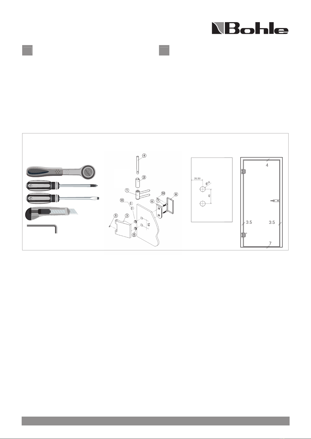
1. Rahmenteil (1) in die Zarge einbauen. (Beiligende
Rahmenteile sind für DIN-Norm-Zargen geeignet.
Weitere Rahmenteile fi nden Sie im Onlineshop unter
www.bohle-group.com). Abdeckhülse (2)
aufschieben.
2. Bandteil (3) mit Rahmenteil (1) durch Bandachse (4)
verbinden und mit Madenschraube M4x4 (5) sichern.
3. Glastür auf 7mm Holz oder Kunststoffklotze stellen.
Seitliche Luft zwischen Glastür und Zarge
gleichmäßig ausrichten.
4. Bandteil (3) mit Klemmplatte (6), Senkkopfschrauben
M6x22 (7) und Glasschutzring (9) mit einem
Drehmoment von 12Nm verschrauben. Dabei die
Glastür endgültig ausrichten. Die Glasschutzringe (9)
fi xieren das Band auf der Türe. Sollte es notwendig
sein, die Türe auszurichten, können alternativ die
Schutzhülsen (11) für die Schrauben verwendet
werden.
5. Bandkappen (8) aufsetzen und mit Madenschrauben
(10) befestigen.
EN
Mounting Instructions
BO 5206670, BO 5206671, BO 5206672, BO 5206673
Bohle Glass door lock Studio incl. 3 part hinges, handle,
frame pivot for timber frames
General information:
- The lock box is compatible with profi le cylinders
according to DIN 18252 (division 21/26)
- Before installation, clean the glass in the clamping area
with a glass cleaner (for example, BO 5107805)
1. Fit the frame part (1) into the frame. (Supplied frame
parts are suitable for DIN standard frames. Further
frame parts can be found in the Onlineshop at
www.bohle-group.com). Place the cover sleeve (2)
on the frame part (1).
2. Connect the hinge plate (3) to the frame part (1)
through the hinge axle (4) and secure with the M4x4
(5) screw.
3. Place glass door on 7mm wood or plastic block.
Align the lateral gap evenly between the glass door
and the frame.
4. Screw the hinge plate (3) clamping plate (6),
countersunk head screws M6x22 (7) and glass
protection ring (9) together with a torque of 12Nm.
Align the glass door. The glass protection rings (9)
fi x the hinge on the door. If necessary, alternatively
the protective sleeves (11) for the screws can be
used to align the door.
5. Place the cover caps (8) and secure them with grub
screws (10).
Benötigte Werkzeuge:
Required tools:
Montage Glastürband:
Installation glass door hinge:
Glasbearbeitung Glastürband:
Glass processing for glass door hinges:
Bohle AG · Dieselstraße 10 · D-42781 Haan · T +49 2129 5568-0 · [email protected] · www.bohle.com
4 Nm
12Nm
3 mm
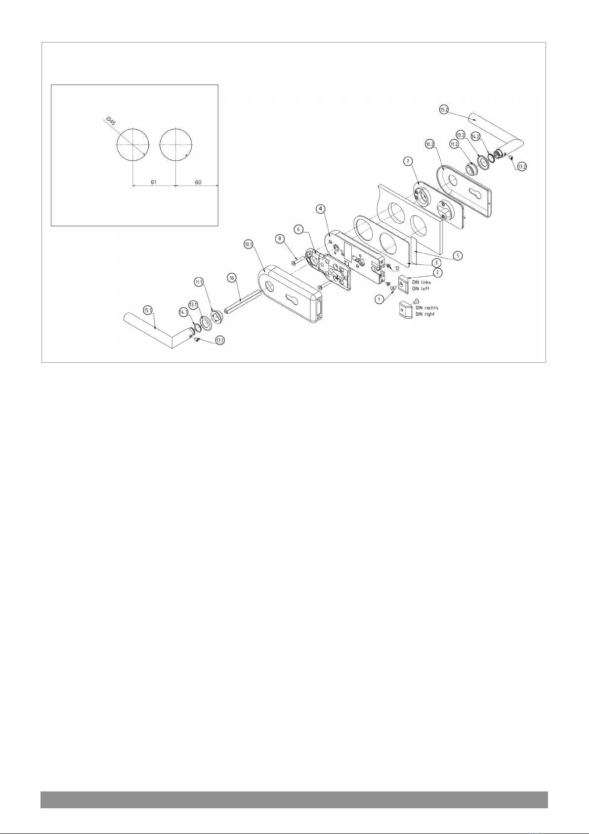
1. Auslieferungszustand DIN Links, Falle für 8 mm Glas.
2. Ändern der DIN-Richtung: Schraube (1) lösen,
Fallenkopf (2) abziehen, drehen und Schraube (1)
wieder festziehen. Die Schräge der Falle muss zum
Glas zeigen! bei 10 mm Glas Falle austauschen.
3. Folie von dem Klebestreifen an der Zwischenlage (3)
abziehen und am Schlosseinsatz (4) befestigen.
4. Folie von dem Aufkleber (5) abziehen und am Glas
befestigen.
5. Schlosseinsatz (4), Montageplatte (6) und Klemm
platte (7) mit Schrauben (8) am Glas montieren
(4Nm).
6. Profilzylinder (nicht im Lieferumfang enthalten) ins
Schloss stecken und mit Befestigungsschraube
sichern.
7. Abdeckkappen (10.1, 10.2) aufstecken.
8. Mithilfe Montageadapter (im Lieferumfang
enthalten) die Drückerführung (11.1, 11.2) in Auf
schraubrosette drücken.
9. Abdeckkappe (10.1) mit Schrauben (12) fixieren.
10. Aufklebestreifen (5) mithilfe eines Messers
abschneiden
11. Rosette (13.1, 13.2) in Drückerführung (11.1, 11.2)
schrauben
12. Gummiring (14.1, 14.2) in Rosette (13.1, 13.2) drücken
13. Türdrücker (15.1) mit Drückerstift (16) durch
Schlossseite durchstecken und mit Türdrücker (15.2)
verbinden. Mit Gewindestiften (17.1, 17.2) sichern
1. Pre-assembled Left handed, latch for 8 mm glass.
2. Changing the direction of the DIN: Loosen the screw
(1), pull the head (2), turn it and tighten the screw (1).
The slope of the trap must point to the glass! The
latch have to be exchanged with 10 mm glass.
3. Remove the film from the adhesive strip on the
intermediate layer (3) and fix it to the lock insert (4).
4. Remove the foil from the sticker (5) and fix it to the
glass.
5. Mount the lock insert (4), the mounting plate (6) and
the clamping plate (7) with screws (8) on the glass
(4Nm).
6. Insert the profile cylinder (not included in the scope
of delivery) into the lock and secure with the
fastening screw.
7. Fit the cover caps (10.1, 10.2).
8. Using the mounting adapter (included in the scope
of delivery), press the trigger guide (11.1, 11.2) in the
screw-on rosette.
9. Fix the cover (10.1) with screws (12).
10. Cut off the adhesive strip (5) using a knife
11. Screw rosette (13.1, 13.2) into lever guide
12. Press the rubber ring (14.1, 14.2) into the rosette
(13.1, 13.2)
13. Push the door handle (15.1) with the push pin (16)
through the lock side and connect with the door
handle (15.2). Secure with threaded pins (17.1, 17.2).
Glasbearbeitung Glastürschloss:
Glass processing for glass door lock:
Montage Glastürschloss:
Installation glass door lock:
Bohle AG · Dieselstraße 10 · D-42781 Haan · T +49 2129 5568-0 · [email protected] · www.bohle.com
This manual suits for next models
3
Popular Door Lock manuals by other brands


Sewosy
Sewosy EF550 installation instructions

Glutz
Glutz HZ-lock VB 19000 Assembly and maintenance instructions

Assa Abloy
Assa Abloy Corbin Russwin Access 800 TCAC2 Series Programming instructions

Soca
Soca SL-150 installation manual

ANXELL
ANXELL AXM-800ML Series Installation instruction

Secuway
Secuway IS-5000 user manual

LaGard
LaGard LGBasic II 3715 User operating instructions

HIK VISION
HIK VISION DS-K4T100 manual

wink haus
wink haus BS80MLM41 operating instructions

Abus
Abus HomeTec Pro CFA3000 manual

Southco
Southco H3-EM-62-100 operating instructions

Abus
Abus HomeTec Pro CFA3000 Supplement to installation instructions and user guide