bolid S2000 User manual

RS-485/RS-232-TO-ETHERNET INTERFACE
CONVERTER
S2000-Ethernet
User’s Manual

3
TABLE OF CONTENTS
1
S2000-Ethernet Description and Operation ....................................................................4
1.1
General ....................................................................................................................... 4
1.2
Specifications .............................................................................................................. 4
1.3
Standard Delivery ....................................................................................................... 4
1.4
S2000-Ethernet Operation ......................................................................................... 5
1.4.1
Li ht Indication ..................................................................................................... 5
1.4.2
Jumper Positions ................................................................................................... 7
1.4.3
General S2000-Ethernet Application Dia rams .................................................... 7
1.4.4
Preparin the S2000-Ethernet for Operation ..................................................... 10
1.4.4.1
Confi urin the S2000-Ethernet ................................................................. 10
1.4.4.2
Settin s Timeouts and Delays ..................................................................... 20
1.4.5
Typical Schematics for Usin the S2000-Ethernet as Part of an Orion system ... 22
1.4.6
An Example of Settin Confi uration Parameters of the S2000-Ethernet .......... 25
1.4.6.1
Settin s for a Typical Dia ram of Connectin the S2000-Ethernet in the
Mode of Virtual COM Port (Retranslatin Data between the Computer and the
S2000-Ethernet) ...................................................................................................... 25
1.4.6.2
Settin a Typical Connection for Retranslatin Data between S2000-
Ethernet Converters ................................................................................................ 26
2
Operation Guidelines.....................................................................................................32
2.1
Connection Dia ram ................................................................................................. 32
2.2
Connectin the S2000-Ethernet to a LAN ................................................................. 32
3
Overall and Mountin Dimensions ................................................................................33
4
Manufacturer Address ...................................................................................................33

4
This User’s Manual is designed to help in studying of principles of operation and maintenance
of the S2000-Ethernet converter of version 2.52.
1S2000-Ethernet Description and Operation
1.1 General
1.1.1 S2000-Ethernet Interface Converter (hereinafter referred to as S2000-Ethernet) is
designed to translate RS-485/RS-232 data to Ethernet and back. Can be used as part of an Orion,
Orion Pro, or any other system.
1.1.2 The S2000-Ethernet is to be installed within protected premises and designed for round-
the-clock operation.
1.1.3 The converter is not designed to be used in aggressive or dusty conditions or in explosive
and flammable premises.
1.2 Specifications
1.2.1 The S2000-Ethernet is to be powered by an external 12 V / 24 V dc power supply with
output voltage of 11 V to28.4 V. We recommend you to use Bolid manufactured battery backed
power supplies RIP-12 or RIP-24.
1.2.2 Current consumed in quiescent mode:
−90 mA max @ 12 V;
−50 mA max @ 24 V.
1.2.3 RS-485/RS-232 Interface (half-duplex):
−Baud rate: 1200, 2400, 9600, 19200, 38400, 57600, 115200 bps;
−Start bits: 1;
−8 data bits/1 stop bit or 8 data bits/2 stop bits;
−Parity: none;
−Max packet size: 255 bytes.
1.2.4 Ethernet Interface:
−Speed: 10 Mbps;
−Adjustable half / full duplex;
−Protocols: UDP, ICMP (ping), ARP;
−Receiving / transmitting unicasts and broadcasts;
−Max number of similar interface converters to which the S2000-Ethernet retranslates
data over the Ethernet channel: 9 or 8 (depending on the configuration);
−Support operation in Ethernet networks of different topology («point-to-point»,
«star», «tree», «mesh»).
1.2.5 Dimensions: 102 mm x 107 mm x 39 mm.
1.2.6 Weight: 200 g max.
1.2.7 Ingress protection rating: IР20.
1.2.8 The pre-operation time after powering up doesn’t exceed 3 s.
1.2.9 Operation Temperatures: minus 30 to +50°C
1.3 Standard Delivery
Table 1. S2000-Ethernet Standard Delivery
Item Qty
S2000-Ethernet Interface Converter 1
This User’s Manual 1
Wood Screws 3
Wall Plugs 3
DIN 7982 Flat Head Tapping Screw with Cross Drive 2.2x6.5 1
S2000-to-PC Cable (to connect the S2000-Ethernet to a PC) Comes
separately
Package 1

5
1.4 S2000-Ethernet Operation
1.4.1 Light Indication
READY LED is green, RS-232/RS-485 LED is green, ETHERNET LED is green.
Table 2 shows the behavior of READY and RS-232/ RS-485 light indicators.
Table 2. READY and RS-232/RS-485 Light Indicators
Light Indicator
Destination
On Off
READY The device is switched on The device is switched off
RS-232
RS-485
Transparent Mode and
Master/Slave Event
Save Mode
Receiving data at the active
interface: RS-232 or RS-485 No data received at the active
interface: RS-232 or RS-485
Configuration Mode Receiving data over RS-232 No data received from RS-232
Light behavior of ETHERNET LED is shown in Table 3. ETHERNET LED also performs an
additional function to indicate conditions of communications for all data communication directions.
Light behavior is defined for each direction and the direction of the highest priority is activated.
Potential directions are defined by IP addresses given in the remote device list of the converter as
well as permission to connect to an unknown address (if permitted by the configuration and
connection has been established). Light behavior highlighted with grey means that communication
has been established and data can be communicated with all possible directions. The modes not
highlighted with grey should draw your attention because they mean absence of an IP partner or
gateway specified in the remote device list, or mismatching of Master Keys of the S2000-Ethernet
and the IP partner, or remote device list’s being empty. In the process of deriving a link channel and
establishing a connection light behavior not highlighted with grey can be observed for a short time.
But if, otherwise, this behavior is active for a long time then:
–Ensure the gateway and IP partners given in the configuration are physically available.
–Inspect the configuration of all IP partners of the converter.

6
Table 3.
ETHERNET
LED
S2000-Ethernet Operation Mode
Configuring
The list of remote devices is
empty
Established Connection
-
Communication has been
lost for more than T
2
s
Communication is been
establishing
1
No link can be established
because the device/gateway
from Remote Device List is
not available
2
Not connected to the local network
T
2
stands for the configuration parameter Communication Failure Indication Delay (30 s by default)
Below
are possible reasons for communication failures:
1
- IP partner is absent (if the IP partner is in another network, beyond the gateway)
- Master Key of the device and Master Key of its IP partner don’t match
2
- The gateway is absent (if the IP partner is in another network, beyond the gateway)
- The IP partner is absent (if the S2000-Ethernet and the IP partner are within the same network)
Transparent
S2000-Ethernet 1.X
The list of remote devices is
empty
For
last
T
2
s data to be
transmitted to RS-485/232
have been received
For last T
2
s data to be
transmitted to RS-485/232
have not been received
-
-
No link can be established
because the device/gateway
from Remote Device List is
not available
2
S2000-Ethernet 2.X
The list of remote devices is
empty
For
last
T
2
s data to be
transmitted to RS-485/232
have been received
For last T
2
s data to be
transmitted to RS-485/232
have not been received
Communication has been
lost for more than T
2
s
Communication is been
establishing
1
No link can be established
because the device/gateway
from Remote Device List is
not available
2
Event Save Mode
Master
The list of remote devices is
empty
Established Connection
-
Communication has been
lost for more than T
2
s
Communication is been
establishing
1
No link can be established
because the device/gateway
from Remote Device List is
not available
Slave
The list of remote devices is
empty
Established Connection
-
Communication has been
lost for more than T
2
s
Communication is been
establishing
1
No link can be established
because the device/gateway
from Remote Device List is
not available
2
Behavior
Flashes on for 3 s
and off for 0.25 s
Lit steady
Flashes: on for 1
s and off for 0.1 s
Flashes: on for 2
s and off for 1 s
Flashes: on for 1
s and off for 1 s
Flashes: on for
0.25 s and off for
0.25 s
Off
Low priority –> High priority

7
1.4.2 Jumper Positions
Starting from the version 2.50, the position of the jumper on the terminal XP2 (see Figure 1)
defines a group of the device operation modes: Working Group and Special Group. Squares shown
in color mean set positions of the jumper.
Special Group comprises the configuration mode. It provides configuring the device (by means
of UProg Configuration Tool) and updating the device version (by means of Orion_Prog program)
over the RS-232 interface.
Working Group includes the transparent mode, the Master event save mode and the Slave event
save mode. Any jumper position other than Config activates Working Group but doesn’t specify the
mode. The type of mode is defined by the configuration parameter Operation Mode.
Figure 1. Selecting a Group of S2000-Ethernet Operation Modes
1.4.3 General S2000-Ethernet Application Diagrams
Figure 2 shows a general diagram for using the S2000-Ethernet as part either of an Orion system
or any other system.
Figure 2. General S2000-Ethernet Application Diagram
A single S2000-Ethernet can retranslate data to (maximum):
–8 remote IP addresses if connection with an unknown address is permitted by the
relevant configuration parameter;
–9 remote IP addresses if connection with an unknown address is not permitted by the
relevant configuration parameter.
All the schemes shown above assume that connection with an unknown address is permitted.
To increase the number of remote S2000-Ethernet converters, on the side «A» several S2000-
Ethernet converters should be used. Each such S2000-Ethernet on the side «A» will retranslate data
over the local network to its remote S2000-Ethernet converters (for example, Scheme B).

8
Figure 3 shows common diagrams (A – F) for using S2000-Ethernet within an Orion system.

9

10
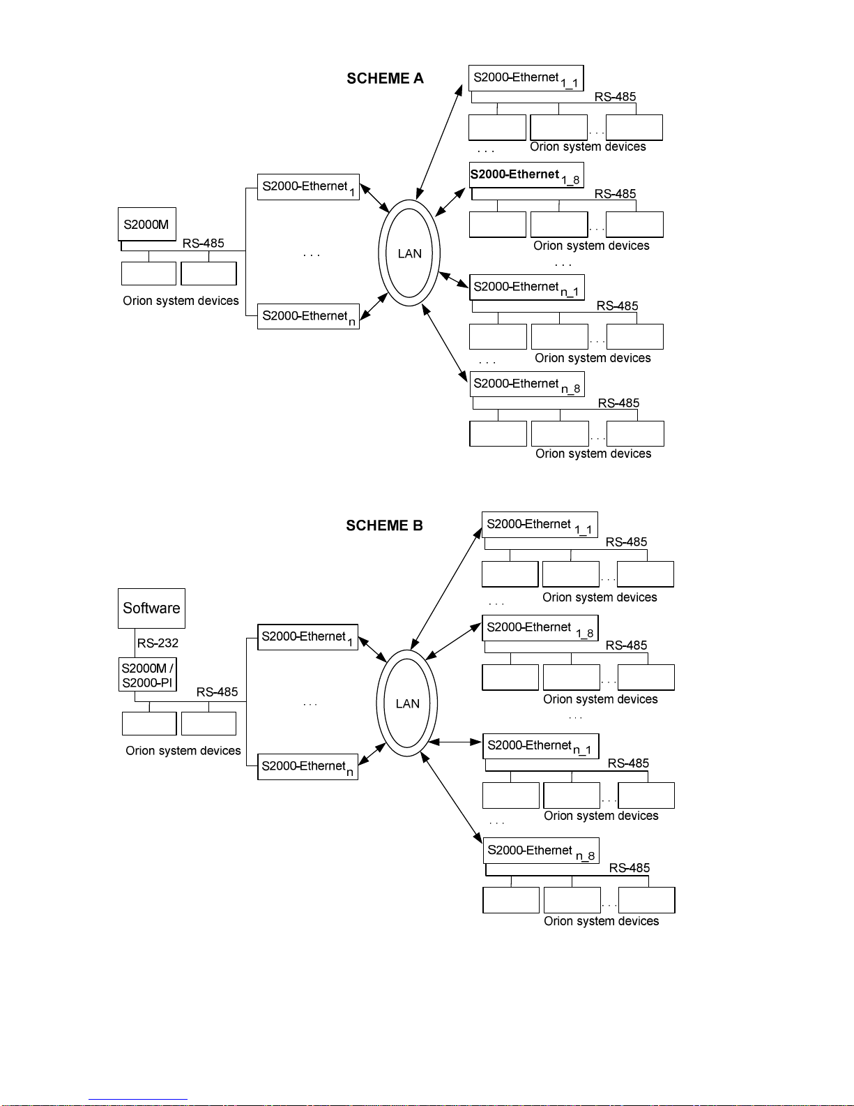
Figure 3. Common Diagrams for Using the S2000-Ethernet as a Component of an Orion System
1.4.4 Preparing the S2000-Ethernet for Operation
1.4.4.1 Configuring the S2000-Ethernet
Editing configuration parameters of the S2000-Ethernet is to be performed by means of UProg
Configuration Tool. The last version of UProg is available at the site http://bolid.com in Software
Section. Configuration parameters of the S2000-Ethernet along with their ranges and default values
are shown in Table 5. Devices S2000-Ethernet of v.2.52 and higher support two ways to change
device configuration: over the RS-232 interface (as before) and over the LAN (new). The relevant
way to configure the S2000-Ethernet is to be selected by means of UProg (such selecting is
supported for UProg of v.4.1.0.52 and higher; configuring the S2000-Ethernet via a PC COM
port is supported by all versions of UProg). Detailed instructions how to configure devices over
the local network with the help of UProg is available at the site http://bolid.com (Section
“Software”).
Configuring the S2000-Ethernet over the RS-232. To configure the S2000-Ethernet over the
RS-232, connect the S2000-Ethernet to a COM port of the PC and switch the device in the
configuration mode (jumper position: Config) – see Figure 1.
Configuring the S2000-Ethernet over the LAN (with the help of Orion 2 Device Interface
Protocol Service). The factory value of the IP address of the S2000-Ethernet is 192.168.127.254.
The device can be configured over the LAN in all operation modes (including Config). To have an
access to the device configuration over the LAN, do the following in UProg:
•Set Orion 2 service access parameters (for communicating with devices using the Orion 2
protocol): specify the IP address of the PC where the service has been installed and the
service port.
•Select the Orion 2 Service branch in the Device Tree and add a new line specifying the
parameters as shown in Table 4.
Access to reading and changing of the device configuration is granted if:
•IP address of the PC with the service «Orion 2 - Device Interface Protocol» is specified in
Remote Device List in S20000-Ethernet configuration. In this case, to have an access to the
S2000-Ethernet the following configuration parameters of the S2000-Ethernet are required:
UDP port (with the default value of 40000) and the Master key of the relevant record of
Remote Device List;
•IP address of the computer where the driver has been installed is not specified in the list of
remote devices, but connection with the unknown address is permitted in the device
configuration (it is permitted by default) and this connection is not occupied by anybody at
the moment. In this case, to access the S2000-Ethernet the following configuration
parameters are required: UDP port of the S2000-Ethernet for unknown address (factory
value 40001) and Master key for unknown address.

11
Factory values of Master keys of the device correspond to the default values in the UProg. If the
computer where the driver is installed and the device are located in the same local network then to
detect the S2000-Ethernet with the help pf UProg you should use either broadcast search (activated
in UProg by default) or adding by IP address. If the computer where the driver is installed and the
device are in different local networks then to detect the device by UProg you need to use the
procedure of adding by IP address; in this case IP address of the S2000-Ethernet should be specified
in the relevant menu. Please take into account then to detect the S2000-Ethernet located in the other
local network, the configuration of the S2000-Ethernet should include the IP address of the gateway
through which the other network can be accessed.
Table 4. Matching between Parameters of the UDP Line and the S2000-Ethernet in UProg
UProg Parameters
Configuration Parameters of the S
2000
-
Ethernet
IP
address
*
is included in the
list of remote devices
IP
address
*
is not included in
the list of remote devices
UDP-Port of the Line
Use the Same
Port for Reading
and Writing
UDP Port Type of the Remote
Device UDP Port Type of the Remote Device
for an Unknown Address
Static Dynamic Static Dynamic
On UDP port of the
remote device -**
UDP port of the
remote device
for an unknown
address
-**
Off UDP port of the
remote device Invalid
Combination
UDP port of the
remote device
for an unknown
address
Invalid
Combination
UDP Port of Remote
Devices UDP Port of the S2000-Ethernet UDP Port of the S2000-Ethernet for
an unknown address
UDP Port of the Device (to
be given when the device
is added manually)
IP Address of the Device
(to be given when the
device is added manually) IP address of the S2000-Ethernet IP address of the S2000-Ethernet
Master Key Master key of the relevant IP record-
of the Remote Device List Master key for an unknown address
IP address* stands for the IP address of the computer where «Orion 2 - Device Interface
Protocol» service is working
** The value of the listening UDP port of a remote device is dynamically updated from Source
UDP Port ("Write Line UDP Port") of incoming packets. “Write Line UDP Port” takes the same
value as “Line UDP Port” if the parameter «Use the Same Port for Reading and Writing» is active;
otherwise the IP address* opens any vacant UDP port.
Please find out the IP address of the S2000-Ethernet, IP address of the gateway, and the
subnet mask from the administrator of that local network where the device is to be installed.
Table 5. Configuration Parameters of the S2000-Ethernet
Group Parameter Range
Default Value and
Format
RS-485/RS-232 Settings
RS-485/RS-
232
Operation Mode Master;
Slave;
Transparent Transparent
S
2000
-
Ethernet
Address for
Configuring over
RS
-
232
1…127 127
Interface Type RS485; RS232 RS485

12
Group Parameter Range
Default Value and
Format
Baud Rate
1200
;
2400
;
9600
;
19200
;
38400
;
57600
;
115200
9600
Data Bits and Stop Bits
8
data bits
, 1
stop bit
;
8
data bits
,
2 stop bits
8 data bits, 1 stop bit
Protocol Other;
Orion;
Orion Pro Orion
Extended Settings for Transparent Mode
Extra Attributes of Data Packing:
Timeout
Off
Length
Off
Delimiter
Off
If
Timeout
is
not
set
,
RS
-
485/
RS
-
232
data
are
transmitted
to
the local network when since receiving the last byte the time
has elapsed equal to the time to transmit two bytes
Timeout (ms) 0 … 4095 0
Maximum Sending Size 1…255 0
Delimiter (hexadecimal form) 0…FF 0
Delimiter Action
(if active)
•
Send All
Data With
Delimiter;
•Send All Data Without
Delimiter;
•Receive One Byte More
After Delimiter and
Send
Send All
Make a Pause on Sending
On
;
Off
Off
Sending Pause (ms) 0…4095 0
Extended
Settings of
Master Mode
Generate Messages about Access
Events On;
Off On
Ethernet Settings
Device Network Settings
Communication Mode Half-duplex; full-duplex Half-duplex
MAC Address
Should be the same as the
MAC address on the S2000-
Ethernet board under the
barcode
Read-only, 6 hexadecimal
numbers (e.g.:
00:18:BC:09:F5:07)
IP Address of S2000-Ethernet – 192.168.127.254
Subnet Mask – 255.255.255.0
Gateway – 0.0.0.0
UDP Port of S2000-Ethernet 0…65535 40000
Acknowledgement Timeout (ms) 1…65535 80
Remote Device List
(Routing Table)*
IP addresses of remote devices to
which data are retranslated over
the Ethernet (IP Address) –
192.168.127.
1
0.0.0.0
0.0.0.0
0.0.0.0
0.0.0.0
0.0.0.0
0.0.0.0
0.0.0.0
0.0.0.0
Remote Device UDP Port 0…65535
9
UDP
ports
40000

13
Group Parameter Range
Default Value and
Format
Remote Device UDP Port Type
Dynamic
;
Static
Static
Compatibility
S
2000
-
Ethernet (
Auto
)
S2000-Ethernet 1.X;
S2000-Ethernet 2.X;
Other devices
S2000-Ethernet (Auto)
Master
Key
(
Encryption Key
)
–
9
Master
keys
(
only for
writing
)
Connection with an
Unknown Address
An Unknown Address Permitted
On
;
Off
On
S2000
-
Ethernet UDP Port for
Unknown Address
0…65535 40001
Remote Device
UDP
Port
(
Only for static
UDP
port
)
0…65535 40001
UDP
Port Type for
Unknown
Address
Dynamic
;
Static
Static
Master
Key for Unknown
Address
– Only for writing
Link
Control
Search Time (s) 1..255 10
Connection Lifetime (s) 1..255 120
Communication Failure
Indication Delay (s) 1..255 30
Description of Configuration Parameters
RS-485/RS-232 Settings
Group «RS-485/RS-232»
Operation Mode:
−Transparent Mode. Transmits data from the RS-232 or RS-485 interface to Ethernet and
back. Designed to be used both as a part of an Orion system (for protocols Orion and Orion
Pro) and for another systems (see Figure 2).
−Master Event Save Mode (S2000-Ethernet-Master). Polls the devices in the remote
segment of the RS-485 interface. The event log can store up to 255 events. This mode is
used only in a system with the Orion communication Protocol.
−Slave Event Save Mode (S2000-Ethernet-Slave).Gathers data from the remote
S2000-Ethernet (from S2000-Ethernet-Master) and transfers them to a Master-device of the
system such as Orion Workstation, Orion Pro Workstation or other software (only for Orion
protocol), or S2000M console. The event log can store up to 255 events.
The system of S2000-Ethernet devices shall be built in accordance with one of the two
following rules:
1) All devices operate in transparent mode;
2) All devices operate in save modes. An event save mode (compared to the transparent
mode) increases the speed of communication between Orion system devices and decreases
the size of data transmitted over the local network. S2000-Ethernet converters connected to
a Master device of the system operate in the Slave Event Save mode while all remote
S2000-Ethernet converters operate in the Master Event Save mode. Master device of the
system is the software which implements polling in Orion protocol or an S2000M console.
Interface Type:
Select the type of the interface which data the configured S2000-Ethernet is supposed to
translate to the local network.
For the transparent mode, that interface is to be activated which is defined by this
configuration parameter.
For Master and Slave modes, an active interface is to be searched. Search begins with the
interface which is written in the configuration parameter. Please take into account that the

14
active interface is searched once on powering up the device (including resetting the device
and changing its configuration). Setting Interface Type in a mode with saving events is nor
obligatory, but for faster searching of the active interface we recommend you to specify the
interface being in use.
Protocol:
For Master and Slave modes select the “Orion” value.
For Transparent Mode the protocol type defines the rules of optimization and sending data
to RS-232/RS-485 and Ethernet:
Orion - The mode with optimizing data. Only three last packets are retranslated
to the interfaces. In case of more packets the older packets are
considered as outdated and are discarded. If extended settings for the
transparent mode are not given then:
a) When data are being received in the RS-232/RS-485 interface then
the packet terminator is a pause equal to a time to transmit three
bytes;
b) When data (received from the local network) are being sent to the
RS-232/RS-485 interface then between the packets a pause is
inserted equal to a time to transmit three bytes.
Orion Pro,
Other - The modes without optimizing data. All data received in one interface
are retranslated to another interface. If extended settings are not
defined for the transparent mode than:
a) In the RS-232/RS-485 interface the packet terminator is a pause
equal to a time to transmit three bytes;
b) Packets received from the local network are sent to the RS-232/RS-
485 interface without pauses.
When the S2000-Ethernet is used within an Orion system:
–Orion Pro protocol (including «Other») is correct only for that connection diagram
in which the S2000-Ethernet retranslates data between the computer and an S2000M
console if in operating condition the console is in the S2000 & PC mode.
–Orion protocol is correct for all connection diagrams.
When using the S2000-Ethernet as part of a third-vendor system, you can select any
protocol: with optimization (“Orion”) or without optimization (“Orion Pro”, “Other”). If
necessary you can correct the rules of transmitting data for selected protocol type using
extended settings for the transparent mode.
Note: The protocol “Orion Pro” is used within the segment of communicating data between
a computer and an S2000M console being in the S2000 & PC mode. In other segments of the
Orion system as well as in the segment between the computer and an S2000M console being
in the S2000 / PC mode or Programming mode, the Orion protocol is used.
Baud Rate:
The baud rate for operating the S2000-Ethernet over the interface RS-232/RS-485.
For Master and Slave modes the value of the parameter is defined by the selected type of
the protocol. This parameter cannot be changed for these modes.
For the transparent mode:
When using the S2000-Ethernet as part of an Orion system, set the value of this parameter to
–9600 or 19200, if the S2000-Ethernet retranslates data between the computer and
the S2000M console operating in the S2000&PC mode. This value must be the
same as the baud rate of the console over the RS-232;
–9600 for another connection diagrams.
Using the S2000-Ethernet in a third-vendor system set this parameter to a value which is
relevant for working conditions of this system.

15
Data Bits and Stop Bits:
The setting is relevant only for the transparent mode. When using the S2000-Ethernet as part
of an Orion system, select «8 data bits, 1 stop bit». When using the S2000-Ethernet as part of
a third-vendor system, set the value in accordance with working conditions of this system.
RS-232 Address:
The address of the S2000-Ethernet, in order to access this one over the RS-232 interface. In
particular, this is the address at which the program «UProg.exe» detects the S2000-Ethernet.
The S2000-Ethernet is an addressable device in the RS-232 interface only in configuration
mode.
Group «Extended Settings for Master Mode»
Generate Messages about Access Events:
If this attribute is set on the S2000-Ethernet independently informs Orion system devices in
the local interface RS-485/RS-232 about granting access and passages generated by the
devices of this interface. In such a way the devices of the local interface are informed about
the events mentioned above more quickly that is important when using anti-passback rules in
an access control system. In such case the SC2000-Ethernet does not translate to the
interface similar information received from the main Master device of the system (a console
or software). This attribute is used exclusively in the Master Event Save Mode when the
S2000-Ethernet is a Master device for the local interface RS-485/ RS-232.
Group «Extended Settings for Transparent Mode»
Make a Pause on Sending:
If this attribute is set on then after transferring a portion of data received from the local
network to the RS-232/RS-485 interface a pause must be made. For an Orion system it is
sufficient to specify the type of the protocol in use and is not recommended to set this
attribute (in this case presence of a pause and the pause value is defined by the selected type
of the protocol).
Sending Pause:
The value of the pause which must be made after sending data to the interface RS-232/RS-
485 before sending the subsequent data received from the local network. The parameter is
considered only if the relevant attribute, Make a Pause on Sending is set on.
Extra Attributes of Data Packing:
For Orion and Orion Pro systems we recommend you not to set this parameter on, that is, to
keep this parameter at its default value.
If Extra Attributes of Data Packing are set off then data of RS-485/RS-232 are transmitted to
the local network if after receiving the last byte the time has elapsed equal to the time to
transmit 3 bytes (according the established transmission rate).
Extra attributes of packing data are the additional marks with which the S2000-Ethernet
understands that the data received over RS-232/RS-485 shall be transmitted to the Ethernet
network.
This parameter and the relevant settings below are designed to be used in third-vendor
systems. If necessary you can set on one or several attributes of packing data. RS-232/RS-
485 data will be transmitted to the local network if at least one of the set attributes is true.
▫Delimiter:
The delimiter is a byte which receiving causes the S2000-Ethernet to send data
received over the RS-232/RS-485 interface to the local network (in accordance with
the rules defined by the subsequent parameter, Delimiter Action). This parameter is
given in the hexadecimal form. The parameter is considered only if the Delimiter flag
is set on.
▫Delimiter Action:
The parameter defines what should be done with the delimiter and RS-232/RS-485
data after receiving the byte of the delimiter.

16
•Send All Data with Delimiter: After receiving the delimiter to transmit to the local
network all received bytes and the delimiter.
•Send All Data without Delimiter: After receiving the delimiter to transmit to the
local network all received bytes without the delimiter.
•Receive One Byte More after Delimiter and Send: After receiving the byte of the
delimiter to receive one byte more and transmit to the local network all received
bytes.
The parameter is considered if only the relevant attribute, Delimiter is set on.
▫Timeout:
If no data have been received over RS-232/RS-485 within the time given by this
parameter then data received until this moment must be transmitted to the local
network.
The value of the parameter is considered only if the relevant attribute, Timeout is set
on. If the given timeout is less than the time to transmit 2 bytes (according to the
established transmission rate) it will be automatically round up to the time to transmit
2 bytes.
If Timeout is not set on then the received data are transmitted to the local network as
soon as after receiving the last byte the time has been elapsed equal to the time to
transmit 3 bytes (according to the established transmission rate).
▫Maximum Sending Size:
The number of bytes which must be received before transmitting the data to the local
network. The value of the parameter is considered if the relevant attribute, Maximum
Sending Size is set on.
Ethernet Settings
Group «Device Network Settings»
IP address of S2000-Ethernet:
Enter the IP address which the S2000-Ethernet will be assigned to in the local network.
Subnet Mask and Gateway:
Enter the subnet mask and the IP address of the gateway through which access to another
network will be granted. A set of the devices in the subnetwork are defined by the subnet
mask. For instance, for the mask 255.255.254.0 devices are located in the same local
network if all 23 bits of three high bytes of their IP addresses coincide. If at least in one bit
from the 23 bits the addresses disagree then the devices are located in various networks.
UDP Port of S2000-Ethernet:
UDP Port of S2000-Ethernet is the UDP port which is open in the S2000-Ethernet for
receiving / transmitting data in those cases when the S2000-Ethernet communicates data
with IP addresses included to the list of remote devices (the S2000-Ethernet sends data from
this UDP port and expects to receive data at this UDP port). Be default, it is the port 40000.
Communication Mode:
The mode of communication of the S2000-Ethernet over the local network: half-duplex or
full-duplex. Automatically network equipment detects the S2000-Ethernet as a half-duplex
device. The S2000-Ethernet can operate in full-duplex mode only if it is connected to a
managed network device (which can be manually configured to operate at selected ports, for
example, a managed switch or router). If extended setting of the network equipment is not
expected, we strictly recommend you to keep half-duplex mode.
Acknowledgement Timeout:
This is a time-out for waiting a reply acknowledging receiving data (an acknowledgement
from the IP address).
Acknowledgement Timeout = The time to transmit a packet to an IP address * 2 + 50 ms
«The time to transmit a packet to an IP address * 2» is equal to the ping’s round trip time
(RTT). If RTT is less or equal to 30 ms then remain Acknowledgement Timeout equal to 80
ms (as set by default). So, issue a ping from any computer in the local network at the side of

17
the programmed S2000-Ethernet to IP partners enrolled in the remote device list (or to the
computers located in the local networks where the IP partners enrolled in the remote device
list are). In such a way we define the acknowledgement time-out for all the IP addresses.
Then find the maximum RTT. If this RTT exceeds 30 ms then add 50 ms to this value and
write the final value to the parameter “Acknowledgement Timeout”. A ping command is
entered in the command line of the computer in the following format:
Ping X -n Y
Ping X -t,
where: Xstands for the IP address or name of the computer within LAN,
n specifies the number of requests sent by a ping command,
Ystands for the number of repeated ping commands,
t specifies that ping continue sending requests until interrupted.
For example: ping 192.168.10.98 -n 100
ping 192.168.10.98 -t
A command «ping –t» provides detecting failures in the communication channel namely in
the cases when there is no reply or RTT is significantly more than an average device reply
time. We recommend you to ensure the communication channel is stable. Acknowledgement
Timeout must be set taking into account the maximum round-trip time.
Group «Remote Device List»
IP Address:
Enter the IP addresses of remote devices to which the S2000-Ethernet will retranslate data over
the local network. For example, for the Slave Event Save Mode enter the IP addresses of all
S2000-Ethernet-Master converters, while for the Master Event Save Mode enter the IP address
of the S2000-Ethernet-Slave converter (see Figure 3 for clarity).
Warning: In the configuration of a S2000-Ethernet-Master the IP address of the
S2000-Ethernet-Slave must be written in the first record of the list of remote devices.
Warning: Starting with the version 2.50, a single S2000-Ethernet can retranslate data
maximum to:
- 8 remote IP addresses if connection with an unknown address is permitted;
- 9 remote IP addresses if connection with an unknown address is not permitted.
Remote Device UDP Port:
This is the listening UDP port which is open for receiving data at the relevant remote device
(UDP port to which the S2000-Ethernet transmits data to the remote IP address). The value
of UDP port of the remote device can be dynamically updated during device operation (this
is defined by the type of the UPD port of the remote device). The default is port 40000.
Remote Device UDP Port Type:
If static port is selected then on sending a packet the destination UDP port will be specified
as the value of Remote Device UDP Port which is defined for the current IP record in the
remote device list. If dynamic port is selected than the destination UDP port at first takes a
value specified by Remote Device UDP Port for the current IP record of the remote device
list but in operation this value is dynamically updated from Source UDP Port of incoming
packets. Dynamic port is relevant for a network where the communication channel between
the S2000-Ethernet and a remote device is implemented with the help of the port forwarding
rules which are given at the gateway through which other subnet is to be accessed. In this
case the dynamic port type is relevant for an S2000-Ethernet to which from this gateway
data are retranslated, because it may not be known in advance which UDP port will be open
at the gateway to retranslate data.
Compatibility:
Here the rules of intercommunication with each IP record in the list of remote devices are
defined. If the S2000-Ethernet retransmits data to other S2000-Ethernet converters or Orion
system software then it is recommended:

18
1. To use the value «S2000-Ethernet (Auto) for all IP addresses except for those which
are specified below in the clause 2.
2. For all the S2000-Ethernet converters v2.15 specified at the list of remote devices set
the parameter to the value «S2000-Ethernet 1.X» if the system operates in the
transparent mode and is built in accordance with Scheme A or Scheme B in Figure 3
(and several Orion system devices or several S2000-Ethernet converters are located in
the RS-485 segment of the central S2000-Ethernet).
The parameter is used both in event save modes and in the transparent mode. On selecting a
value «S2000-Ethernet» the device will automatically detect maximum capabilities of a
partner. Operating in the Transparent mode with capability «S2000-Ethernet 1.X» the
S2000-Ethernet doesn’t provide delivery reliability and encryption. These functions are the
responsibility of higher protocols and must be monitored and provided by devices which
data are retranslated using S2000-Ethernet converters. Compatibility «S2000-Ethernet 2.X»
is supported by S2000-Ethernet converters of version v.2.05 and higher.
For compatibility with third-party developments, a possibility to translate data without using
internal headers has been implemented. For this purpose, the device should operate in the
Transparent mode while Compatibility should be set to Other Devices value. In this case RS-
232/RS-485 data are translated to Ethernet in UDP packets where data segments contain
only data of the RS-232/RS-485 interface. As Other Devices we can consider in particular
interface converters of other manufacturers which retranslate RS-232/RS-485 data to a local
network using UDP.
Master Key:
Master Key is used in the Transparent mode if devices intercommunicate with Compatibility
«S2000-Ethernet 2.X» and in an event save mode. If necessary, to increase privacy of data
translated over the local network you can change the Master Key for each remote device (by
default a single key is used for all connections). Please be careful: on changing a Master Key
specify the same Master Key in configuration of the relevant remote device (for example, for
the event save mode the same Master Key must be given both for the S2000-Ethernet-Slave
and for the S2000-Ethernet-Master).
Group «Connection with Unknown Address»
An Unknown Address Permitted:
If this attribute is set on then the S2000-Ethernet is permitted to communicate data with an
IP address not included in the list of remote devices (in this case the IP address should
initiate the connection). Simultaneously only a single connection with an unknown address
is permitted. To connect to an unknown IP address the following parameters should be
specified: S2000-Ethernet UDP Port for Unknown Address and Master Key for Unknown
Address.
S2000-Ethernet UDP Port for Unknown Address:
This is a UDP port which the S2000-Ethernet opens to send / receive data when the S2000-
Ethernet communicates data with IP addresses not included on the remote device list (the
S2000-Ethernet sends data from this UDP port and waits for receiving data from this UDP
port). The default is port 40001.
Master Key for Unknown Address:
Master Key for Unknown Address is designed to limit access to the converter for IP
addresses not included in the remote device list. Please be careful: changing Master Key for
Unknown Address, do not forget to change the relevant Master Key for the relevant IP
address (software or other device).
Remote Device UDP Port for Unknown Address:
Remote Device listening UDP Port for Unknown Address is the UDP port which is open to
receive data at the IP address which is not included to the remote device list (the
S2000-Ethernet sends data to this UDP port). The value of the UDP port for unknown

19
remote device can be dynamically updated in operation (it is defined by the type of UDP
destination port). The default for each IP record is port 40001.
Remote Device UDP Port Type for Unknown Address:
Is static port is specified then the destination UDP port is equal to the value given by the
parameter «Remote Device UDP Port for Unknown Address». If dynamic port type is
specified then the value of Remote Device UDP Port for Unknown Address is filled in and
updated in operation from the field Source UDP Port of incoming packets. Dynamic port is
relevant for a network structure where the communication channel between the S2000-
Ethernet and a remote device is implemented using the rules of port forwarding specified for
the gateway through which another subnetwork can be reached. In this case dynamic port
type is relevant for the S2000-Ethernet to which this gateway retranslates traffic, because the
number of the UDP port open at the gateway for retranslating data can be unknown prior to
operation. The default port type is static.
Group «Link Control»
Search Time:
The parameter performs two functions:
1. In case of a communication loss it defines the period for trying to establish a connection
(or to get service information). By such a way, useless traffic resulting from trying to
connect with a missing remote device can be minimized. The parameter is used in all
operation modes of the device (except for the configuration mode).
2. If a connection has been established the parameter defines to period of checking
connectivity. In accordance with the given period the S2000-Ethernet sequentially
checks communication with all remote devices connection with which has been
established before. The parameter is used in the Transparent mode if the devices
communicate in the second version of the internal protocol (Compatibility S2000-
Ethernet (Auto), S2000-Ethernet 2.X) and in the mode with saving events.
Connection Lifetime:
The value of this parameter must exceed at least twice the Search Time and must exceed
Communication Failure Indication Delay. The parameter performs several functions:
1. Defines a delay between a moment of time when the device has found link
disconnection and a moment of time the device registers a communication loss.
Operating in the Slave Event Save Mode, the S2000-Ethernet-Slave dose not loss the
devices connected to the relevant direction of the S2000-Ethernet-Master during this
time.
2. Within this time efforts are taken to establish connection or to receive service
information from the S2000-Ethernet for which a communication failure has been
detected. In case of not restoring connection within this time than next effort to restore
connection (or to receive service information) are carried out in accordance with Search
Time.
Communication Failure Indication Delay:
The parameter Communication Failure Indication Delay must be less than Connection
Lifetime. The parameter performs several functions defining a time-out since the moment X
on elapsing which ETHERNET LED switches to the relevant light mode (the parameter T
2
from Table 3):
1. In case of encrypted communication with an IP address the parameter defines the delay
in indicating by ETHERNET LED the fact of communication loss since the moment the
communication loss has been detected.
2. For the Transparent mode the parameter defines the time since payload designed to be
transmitted to RS-232/485 have not been received on elapsing which ETHERNET LED
switches to the relevant indication mode.
For example, the default values can be replaced with the following values:
–Search Time: 5 s;
–Communication Lifetime: 10 ;
–Communication Failure Indication Delay: 3 s.

20
The device provides a possibility to change some configuration parameters by means of
combinations of short and long presses on the tamper switch located on the device PCB. A long
press means pressing and holding the tamper switch pressed for more than a half of second but less
than 6 s. A short press means pressing and holding the tamper switch pressed for 0.02…0.5 s. A
pause between presses should be at least 0.02 s. Not pressing the tamper switch for more than 2 s is
considered as the end of pressing. Pressing the tamper switch for more than 6 s cancels the press
combination. All possible combinations and their destination are shown below:
•Resetting the device settings to default values: short-short-long-long-short-short-long-
long;
•Changing the type of the interface RS-232/RS-485: short-short-short-long-long;
•Unsetting the RS-232 address and time parameters of operation in the interface for
Master/Slave modes (the time parameters which are set with the help of RS485Settings):
long-long-long-short.
1.4.4.2 Settings Timeouts and Delays
Table 6. Parameters of RS-232/RS-485 to Be Changed
Master Device of
the System
Operation Mode of the S
2000
-
Ethernet
Transparent Event Save
(only Orion protocol)
Orion Workstation,
Orion Pro
Workstation, and
other software
Request Waiting Timeout*
1
Broadcast Turnaround Delay
(only for Orion Protocol)
1
Command Waiting Timeout
1
Request Waiting Timeout ≥80 ms
Broadcast Turnaround Delay
1
Command Waiting Timeout
3
UProg, PProg Request Waiting Timeout
1
Command Waiting Timeout
1
Request Waiting Timeout ≥80 ms
Command Waiting Timeout
1
S2000M
Session Delay Without Change of
Direction
4
Search Timeout*
1
Broadcast Turnaround Delay
1
EventRequest Timeout *
1
Command Request Timeout
1
Search Timeout ≥50 ms
Broadcast Turnaround Delay
2
EventRequest Timeout ≥80 ms
Command Request Timeout
3
Orion Pro
Workstation, UProg
and other software for
emulating a virtual
COM port
Broadcast Turnaround Delay
(for Orion protocol) ≥10 ms.
LAN Transmission Timeout ≥T Not used
Third-vendor systems Relevant software timeouts
1
Not used
Note:
*– The value of the parameter must be calculated by formula and the double value must be used
if more than one central S2000-Ethernet converter is located within a single RS-485 segment (e.g.,
the scheme B in Figure 3).
1– The value of the parameter is calculated by formula:
)(*15
)1(
msNTXP ++≥
2– The value of the parameter is calculated by formula:
)(
*15
)2(
ms
Y
N
TXP ++≥
3– The value of the parameter is calculated by formula:
)(
)3(
msTXP +≥
4– The value of the parameter is calculated by formula:
)(30
)2()4(
msPP −≥

21
For all formulae:
Xstands for the default value of the parameter;
Tstands for the configuration parameter of the S2000-Ethernet, Acknowledgement Timeout;
Nstands for the number of IP addresses with which the S2000-Ethernet communicates data (in
fact, this is the number of used records in the list of remote devices);
Ystands for the console parameter Broadcast Repeat Number (by default it is 6; must be
at least 3).
Before using the SC2000-Ethernet as a part of an Orion system it is necessary to change
settings of the S2000M console and software as recommended in Table 6. Software parameters
can be changed with the help of the program «Settings.exe» (Table 8). S2000M console
parameters can be changed with the help of the program «RS485Settings.exe». These programs
can be downloaded for free from the site http://bolid.ru.
For S2000-Ethernet converters of earlier versions, the recommendations for setting time
parameters differ from those shown below. If S2000-Ethernet of various versions (v.1.15, v.2.15
and v2.50 and higher) are used in a single systems then time parameters of software and the
console should be adjusted in accordance with the recommendations of the current Manual.
Before using the SC2000-Ethernet as a part of a third-vendor system it is necessary to take
into consideration that S2000-Ethernet converters bring delays in data communications. You
should increase the relevant timeouts for devices or software in accordance with
recommendations in Table 6.
Table 7. Summary Table of Parameters for T = 80 ms, N = 9 and Y = 6 (See above)
Master Device of
the System
Operation Mode of the S
2000
-
Ethernet
Transparent Event Save
Orion Workstation,
Orion Pro
Workstation, UProg,
PProg and other
software
Request Waiting Timeout
1
≥245 ms
Broadcast Turnaround Delay (only for Orion
protocol)
1
≥215 ms
Command Waiting Timeout
1
≥815 ms
Request Waiting Timeout ≥80 ms
Broadcast Turnaround Delay
1
≥215 ms
Command Waiting Timeout
3
≥680 ms
S2000M Console
Session Delay Without Change of Direction
4
≥100 ms
Search Timeout
1
≥225 ms
Broadcast Turnaround Delay
1
≥215 ms
EventRequest Timeout
1
≥240 ms
Command Request Timeout
1
≥800 ms
Search Timeout ≥50 ms
Broadcast Turnaround Delay
2
≥110 ms
EventRequest Timeout ≥80 ms
Command Request Timeout
3
≥680 ms
Orion Pro
Workstation, UProg
and other software
(virtual COM port)
Broadcast Turnaround Delay (only for
Orion protocol) ≥10 ms.
LAN Transmission Timeout ≥100ms. Not Used
In order the S2000-Ethernet to operate as a virtual COM port, the parameter Data
Communicating Device (WorkType) is to be set to «S2000-Ethernet». In this case software (Orion
Pro Workstation, UProg etc.) for the selected logical COM port will communicate data not through
the COM port of the computer but via the network card (local network). The parameter WorkType
is to be set with the help of Settings.exe.
In Table 8 you can see the versions of software for which (and for the versions which are
higher) setting of all parameters specified in Table 5 is supported.
Settings.exe of versions lower than v.2.00 build 14 doesn’t support setting Broadcast
Turnaround Delay (PauseTotalCommand) and Data Communicating Device (WorkType). In this
case a more recent version of Settings.exe should be downloaded.
Software operating in Orion Pro protocol as well as UProg and PProg do not use the Broadcast
Turnaround Delay parameter (PauseTotalCommand) even though it is presented in the list of
parameters. Orion Pro protocol is used for communicating data between a computer and an S2000M
Table of contents
Other bolid Media Converter manuals