bolid RIP-24 User manual

SHUTTING OFF RIP-24
1. Shut off the mains power supply 220 V.
2. Detach the batteries.
3. Remove the fuse F1.
4. Disconnect the load circuit.
MAINTENANCE
The maintenance of the RIP-24 is to be carried out annually. The maintaining operations include:
1) Visual inspection of the RIP-24 to discover mechanical injures and to clean any dirt or dust if presented.
2) Checking the output voltage value when the load is connected as specified in SPECIFICATION and checking
the output voltage value when the RIP-24 is powered by batteries.
3) Testing LED and sound indication to meet the requirements of Table above.
4) Inspection of proper attaching of the RIP-24, tightening of contacts, and wire integrity.
5) Replacing the batteries when necessary but at least once per 5 years.
MANUFACTURER
ZAO NVP BOLID
#4, Pionerskaya Str., Korolev, Moscow Region, Russia, 141070
Tel./fax +7 495 775-71-55
BATTERY BACKED POWER SUPPLY
RIP-24 model 01
INSTRUCTION MANUAL
GENERAL
Battery Backed Power Supply RIP-24 model 01 (referred to as RIP-24 below) is designed to provide electric power
to various fire and intrusion detectors as well as control and indicating equipment suited for uninterrupted 24 VDC.
The RIP-24 is round-the-clock operating device with specified output parameters and sealed backup batteries which
are tested and charged automatically. The RIP-24 provides shutting the batteries off from the load circuit to avoid their
unacceptable discharge.
The RIP-24 provides light and audible indication of its current status, i.e. normal or no voltage, battery charge,
output short failure or overload, battery missing or shutting down when discharged.
Being powered by mains power and by backup batteries, the RIP-24 provides its outputs against short circuit
failures with automatic recovering output voltage after repairing the failures.
When operated, the RIP-24 should be protected against atmospheric fallout and mechanical damage. RIP-24 is not
designed to be used in explosion-hazardous premises.
SPECIFICATION
AC Input Voltage Range: (220+22-33) VAC
Backup Power Supply: twobatteries «Delta» DTM1207 12 V @ 7 Ah or analogous
(with the lifetime of at least 5 years)
No batteries are provided with the power supply
Output Voltage Range: 27.0 ±1.2 VDC at both AC and charged battery powering;
22.0 ±1.0 VDC min provided the battery is discharged
Load Current Rating: 3.0 А
Maximum Load Current: 4.0 Аfor 2 min, once an hour, at both mains and battery power
Input Current Consumption: 0.7 A max at rating load
RIP-24 Consumption From the Battery: 30mAmax
Ripple (mVp-p)×2: 30 mV maximum at rating load current
Battery Low Shutdown: 20.4±1.2 VDC
On Battery Run-Time: at least 5 hours for 1 A load current at 25°C
(the run-time increases in inverse proportion to the load current)
Pre-Operation Time: 3 seconds max
Operating Temperature Range: from –10°C to +40°C
Relative Humidity: up to 90% at +25°C
Overall Dimensions: 340 mm × 270 mm × 100 mm
RIP With Batteries Weight: 12 kg maximum
Typical Lifetime: 10 years, the batteries being to be replaced once every5 year
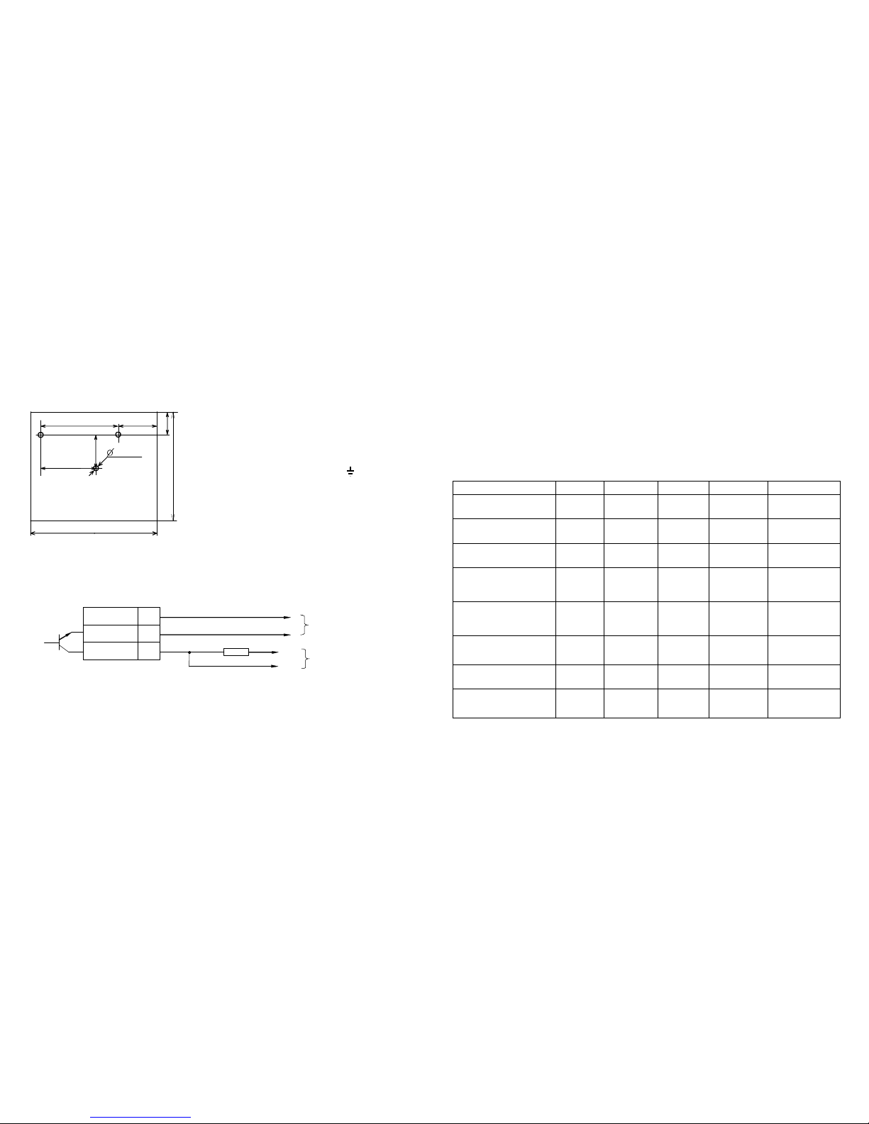
The RIP-24 provides outputting a signal to the NPN output in case of switching to powering by the backup batteries
(in state of no mains power) or a short failure in the load circuit. The NPN output is opened when AC line fails and
the RIP-24 is operating in battery mode or in case of a short load circuit failure, and it is closed when the RIP-24 is
powered by mains power. The maximum NPN output permissible voltage and commutation current are 30 V and
100 mA respectively.
The RIP-24 provides connecting two extra 12 V batteries of 17 Ah each placed in a special Box 2x17Ah to increase the
timeof operation from the batteries (with total capacityof allRIP-24 batteries beingequal to2×24 Ah).
STANDARD DELIVERY
Battery Backed Power Supply RIP-24 mod.01 1
Instruction Manual 1
Fuse 2А1
Round Head Wood Screw 3
Wall Plug 3
Plastic Bushing 2
Wire 1
Lock Key 2

RIP
-
2
4
mod.01
ХТ
3
−24V Output
5
3
+
OC
Output
1
+24V Output
+
–
To the CIE power
supply leads
R 4.7 kΩ
ΩΩ
Ω+loop
–
loop
To the CIE loop
R
is the Loop End-Of-Line Terminator provided with the CIE; it is to be installed within the RIP-24 enclosure
SAFETY PRECAUTIONS
Current-carrying RIP-24 circuits at 220 V are dangerous and can bring human injure.
Ground the RIP-24 properly before operating.
Do periodically inspect proper RIP-24 grounding and fuse operability.
Never open the RIP-24 unless AC line is shut off.
Do shut off AC line power before mounting, installing or maintaining the RIP-24.
Only skilled personnel trained in electric codes and work safety rules should service the device.
ATTENTION!
Connecting the RIP-24 to the mains utility power supply please KEEP UP the correct
coupling of LINE and NEUTRAL TERMINALS in agreement with the picture located inside the cabinet
close to power terminal block.
MOUNTING AND WIRING
1 4 0
2 2 0
2 7 0
3 4 0
5
1 5 4
1 0 0
*
3 holes
1 5
Figure 1
Note: Load current rating is 3 A. The maximum current consumption from RIP-24 can reach up to 4 A
within 2 minutes once per hour in case of activating sound alarms, executive devices, and automated fire
extinguishing systems.
Figure 2
4) To transmit RIP-24 trouble messages about mains power failures or load circuit short failures remotely, connect
the RIP-24 open collector transistor, or NPN output (+OC output) to an alarm loop of a powered control and
indicating equipment, e.g. S2000-4, Signal-20P, etc. The example of such wiring is demonstrated in Figure 2.
STARTING UP
Before the first turning on ensure the RIP-24 mounting has accomplished correctly.
Firstly, connect the batteries to the terminals taking into account the polarity (the red wire is connected to the
positive lead of the battery).
Then, insert the fuse F1.
Finally, turn on mains power 220 V@50 Hz.
OPERATION
a) When AC line is on, the LEDs POWER, 24 V, and CHARGE are lit while RIP-24 sounder remains in silence.
Note: The batteries being completely charged and their voltage being over 26 V, CHARGE LED will not be lit.
b) After powering up the RIP-24, its batteries are tested. If the batteries are not connected or their voltage is below
20 volt then the sounder and CHARGE indicator go off in interrupted mode within 8-10 seconds. After that the
sounder is hushed, but CHARGE indicator flashes until batteries are connected. Battery testing procedure is
carried out periodically (at least once every 8 hours). If no batteries are found, then CHARGE indicator flashes.
c) In the events of a short load circuit failure or an output overload (in AC line operating mode), after 3 s the RIP-24
turns on in the interrupted mode with the interval of 1 -2 second until the trouble disappears. The 24 V and
CHARGE indicators are off. The POWER indicator begins to flash once every 1-2 seconds, the sounder being
sounding in interrupted mode. After failure’s disappearing the RIP-24 automatically continues normal operating.
d) When mains power supply fails the batteries begin to power the load circuit, 24 V indicator being turned on and
the sounder going off periodically. The POWER and CHARGE indicators are off.
e) If the voltage of the batteries has dropped to 22 V the sounder switches on and off five to ten times more rapidly.
It is necessary to take measures to restore mains power line as soon as possible.
f) If the voltage of the batteries has dropped below 20 V, then, to avoid deep discharge of the batteries, the batteries
are shut off from the load. In such case the POWER and 24 V indicators are off, the CHARGE indicator is
flashing, and audible alarm is sounding within two first hours. In 2 hours the RIP-24 will be transferred to low
battery powering mode, with the CHARGE indicator and sounder turning on once every 10 seconds.
If the AC power is expected to be not available for more than 7 days, then, to avoid an overdischarge of the
batteries, disconnect them from the RIP-24 PCB.
LEDs and sound indicator behavior along with required human actions are shown in Table below.
RIP-24 Current Status POWER LED
CHARGE LED
24V LED Sounder Human Actions
Mains power is starting up,
no batteries are connected ON Flashes once
every 1-2 s ON
Sounds for 8
-
10
seconds in
interrupted mode
Connect the batteries
Normal AC line voltage,
the batteries are not charged
ON ON ON OFF -
Normal AC line voltage,
the batteries are charged ON OFF ON OFF -
Normal AC line voltage,
an output overload / short
failure for more than 3 s
Flashes once
every 1-2 s OFF OFF Beeps twice
every 1-2 s Repair load
failure
AC line failed, an
output short failure or
overload OFF OFF OFF OFF Repair load
failure
AC line failed, the battery
voltage is above 22 V OFF OFF ON Beeps once per
4-5 seconds
Inspect
fuse
F1
operability and
recover the mains
line
AC line failed, the battery
voltage is below 22 V OFF OFF ON Beeps once per
0.5-1 second Repair the AC line
AC line failed, the batteries
have been discharged OFF Flashes once
every 1-2 s OFF ON
After
recovering
mains power, test the
battery charge-
discharge cycle
*
Note:
* After detaching the battery from the load circuit and recovering utility power it is necessary to check the battery
charge-discharge cycle. If the CHARGE LED has been still lit after 24 hours since having restored power then
the battery operability has to be checked. If extra batteries are connected the charge time will be increased.
The RIP-24 is to be mounted on a wall or another construction on
premises protected against atmospheric fallout, mechanical damage
and unauthorized access. The RIP-24 mounting dimensions are
shown in Figure 1.
Attach the RIP-24 at the selected location.
Then, in accordance with wiring diagram fixed at internal side of
the RIP-24 door do the following:
1) Ground the RIP-24 coupling the contact " " (XT1/5) located
on the input terminal block with a ground network.
2) Having removed F1 (2 А) fuse, connect mains power supply
wires to the input block terminals. LINE must be connected to
XT1/4.
3)Connect load circuits to the output terminal block keeping the proper
polarity (contacts ХТ3/4,5 to "
+
" and ХТ3/2,3 to "
–
"). If several load
circuits are to be connected to the RIP-24, you are recommended to
use Bolid manufactured BZK DC power distrib
ution modules.
Other bolid Power Supply manuals