Bolin Technology Dante AV D412 User manual

*Items included in the camera boxD412/D220Dante AV Camera x 1VCC-P12-4Power Adaptor x 1VCC-RC-2IR Controller x 1Batteries not included)Safety Hook x 1Used to secure the camera to its mounting solutionD10HDante AV Decoder x 1Items included in the decoder box
1 2 3 4 5
VCC-CC45RSRJ45 to RS422Control cable x 1This quick start guide applies to D412, D220, D10HOptional AccessoriesB-RM10Single Rack Mounting Kit-For Decoder Note: The Dante AV Decoder is mandatory for Dante AV video output.Thank You Card x 1Power Cord x 3(Type: US, EU, UK)Power Adaptor x 1Power Cord x 3(Type: US, EU, UK)1HDMI Cable Mount*1
1 2 3 4 5
VCC-CC45RSRJ45 to RS422 Control cable x 1INOUTVCC-CC45RSControl cable x 1RJ45 to RS232BL-CM-01For DecoderBL-WM-01M4-6PW Screw X3M2.5-3C Screw x 2M4-6PW Screw x 8 M2.5-3C Screw x 8 M3-8K Screw x 4 M5-12P Screw x 4
8*300mm
Cable Tie x 4HDMI Cable Mount x 1For camera bracket mountingFor HDMI cable secure mountingBase Mount Kit x1Surface Mount Kit x 1For Surface Mount Kit mountingFor HDMI cable secure mountingFor base mount kit mountingFor TV surface mountingMini Pole Bracket x 1Dual Rack Mounting Kit-121234

Power Adaptor (DC 12V 4A) to power the camera.When using POE , use IEEE802.3bt certified switch to power the camera.4. Power the CameraWhen powering via both DC 12V and POE , DC 12V takes precedence. Using only one powering method to power the camerais highly recommended.3. Resolution ConfigurationVideo Format0720p501720p60Use a flat screwdriver to set the circular speed dial to the desired resolution. The table below indicates the video formats the camera supports. Choose 1,2,or 3 on the IR Select to control the camera. 12345678++
Note: Power off the camera prior to changing dial settings. Resolution can also be changed via OSD menu once the camera is powered on. Camera will follow the latest configured resolution. Refer to the camera manual for further detail.Infrared Remote control ID, please dial it to the desired location.(Choose "1" when there is only one camera.)++12++
DC 12V 4A2Camera HDMI Output Setup1. Item ListDisplay Output Device x1 (Not included)HDMI 2.0 Cable x1 (Not included)2. Connection DiagramSupports HDMI 2.012345678++Dante AVPTZ CameraDisplay Output DeviceHDMI INHDMI 2.0 Cable ConnectionDC 12V 4A12++++1080p23.98

6. Camera Control via IR Remote123Remote controller Camera ID needs to match the IR Select on the camera for control. Recommended control distanceto be within 10 meters.MenuTWSlowZoomTWFastZoomFor detailed IR remote operation instruction, please refer to camera product manual.Camera OSD menuDirection controlFor fast zooming For slow zooming ++Dante AV Video Output Setup1. Item ListHDMI 2.0 Cable x1(Not Included)Cat6 Network Cable x3Dante AV Decoder x1Display Output Device x 1(Supports 4K60)POE++ 1Gbps Network Switch (Not included)ComputerDante Controller x 12. Install Dante Controller SoftwareDante Controller Download URL:https://my.audinate.com/support/downloads/download-latest-dante-software?lang=zh-hansDante Controller Hardware Requirements:CPU: Minimum of 1GHz processorStorage: At least 512MBNetwork Card: Ethernet connectivity port (1000 Mbps)Dante Controller OS Requirements:Note: 5. Dante AV Camera StartupPOWERThe Power indicatorstays solid green whenthe camera is powered on.POWERSTATUSWait after the camera finishes turning, tilting and scanning its range.Once the on screen display (OSD) menu disappears, the camera is ready for use.HDMI INHDMI 2.0 Cable Connection3(Not Included)(Not included)(Not included)

3. Connection Diagram12345678Dante AVPTZ CameraTwo Ethernet ports available, only Port 1 supports POE++.Network Cable Connection (POE Powered)
POE power via network cableNetwork Cable
Direct Camera HDMI Output
HDMI Output
Dante ControllerPOE++ SwitchDisplay Output DeviceDisplay Output Device
Dante AV Decoder
++Note: ①. DHCP network configuration is recommended.② If network does not support DHCP, please manually configure IP details on the camera and decoder to match the same gateway.③ Switch Requirement: · Nonblocking Layer 2 · Green Ethernet must be OFF (Recommend not using Green Ethernet capable switches) · Use reputable "Managed" switches · Support QoS with strict priority and 4 queues · IGMP Snooping ON · Please refer to product manual at www.bolintechnology.com for IP configuration instructions++①. Power Adaptor (DC 12V 4A) to power the decoder.. When using POE ++ , use IEEE802.3bt certified switch to power this decoder②4. Power on the Decoder
Both DC12V and POE are workable, when powering the camera, DC 12V preferably.
DC 12VDC 12V 4AFor Dante AV camera startup tips, please refer to its respective diagram.Note: 4++++++++++
++

DanteControllerVideo - Network ViewFileDevicesViewHelpRoutingDevice InfoClock StatusNetwork StatusEventsPrimaryLeaderClock:D220-0225a2?Filter Tra ns mitter sFilter Re oeive rsReceivers(2)_+D10H-02263CD220- 0225a2
Transmitters(2)D10H-02263CD220- 0225a2
x
_+
++++5. Dante AV Decoder StartupDante AV Decoder
TM
Switch on the decoder after connecting the powerGreen: NormalGreen: Normal, Not lit: Abnormal/ErrorGreen: Not protected, Green (Blinking): Protected,Red: Abnormal/Error: Green: Normal, Yellow: Starting up, Red: Abnormal/ErrorGreen (Blinking): Normal, Red: Abnormal/ErrorFor Dante AV camera startup tips, please refer to its respective diagram.Note: 6. Display Camera Video via Decoder?x1. Click to choose network interfaceThis is mandatory when there are multiple network connectivity methods on the device.Configure Dante Interfaces in Unmanaged mode Select the network interface that the Dante Controller Use Shared Dante interface Primary Interface: Secondary Interface: Ok IP: 192.168.2.6 MAC: IC:IB:OD:7E:4C:3B Network None IP: No Address MAC: 00:00:00:00:00:00 N/C3. Click to see specific transmitter routing options.+2. Click to see all connected Dante devices.4. Click to see specific receiver routing options.
+
5Green: Dante network clock slave, sync achieved
Green (Blinking): in sync with leader clock,Red: Abnormal/Error
1G

DanteControllerVideo - Network ViewFileDevicesViewHelpRoutingDevice InfoClock StatusNetwork StatusEventsPrimaryLeaderClock:D220-0225a2?Filter Tra ns mitter sFilter Re oeive rsReceivers(2)_+_D10H-02263cD220-0225a2RS-422
Transmitters(2)D10H-02263cUSBIRRS-422D220-0225a2HDMILeftRight
xHDMILeftRightCenterLFESoreenLeftSurroundRight SurroundLeftCenterRightCenterUSBRS-422IR_
_+__
____
RS-422
8. Subscribe Audio TX (Left/Right) to Audio RX (Left/Right), you can subscribe to the left channel or the right channel, or you can subscribe bothDanteControllerVideo - Network ViewFileDevicesViewHelpRoutingDevice InfoClock StatusNetwork StatusEventsPrimaryLeaderClock:D220-0225a2?xDeviceNameSyncMuteClockSourceDomainStatusPrimaryv1MulticastPrimaryv2MulticastSecondaryv1MulticastSecondaryv2MulticastDanteDanteFollowerLeaderDisabledN/AN/APreferredLeaderEnableSyncToExternalDisabledN/AN/AN/AN/AN/AN/AD10H-02263cD220-0225a2DanteControllerVideo - Network ViewFileDevicesViewHelpRoutingDevice InfoClock StatusNetwork StatusEventsPrimaryLeaderClock:D220-0225a2?xDeviceNameModelNameProductVersionDanteVersionDeviceLockPrimaryAddressPrimaryLinkSpeedSecondaryAddressSecondaryLinkSpeedD10H-02263cD220-0225a2Bolin D10HBolin D220 Camera3.1.23.1.24.3.6.104.3.6.10192.168.2.154192.168.2.1551Gbps1GbpsN/AN/AN/AN/A5. In Device Info tab, all connected Dante devices are displayed, if the device is not listed please check its network connectivity.6. Select the Clock Status tab for clock leader. This is optional, Dante Controller software will automatically select a leader if left undefined.6
7. Check to subscribe TX to RXHDMI connection route.

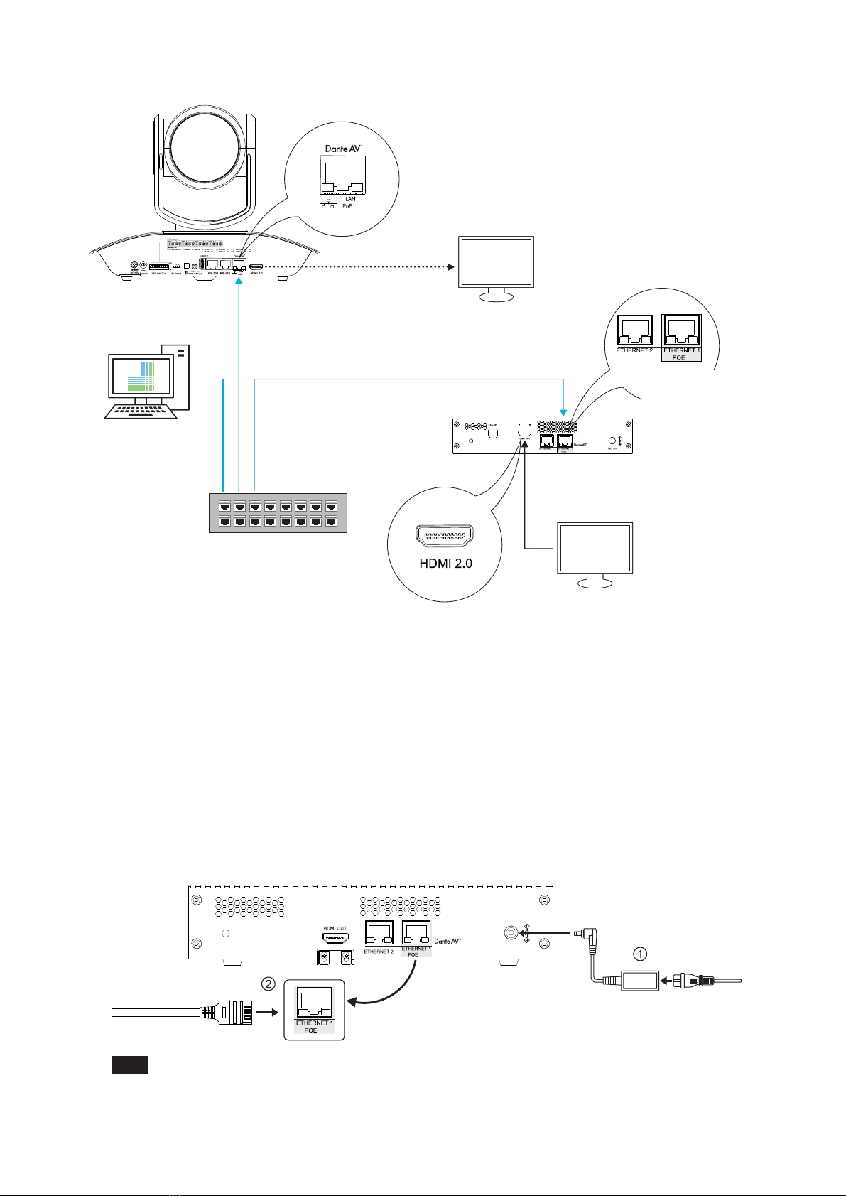
Note:7. Camera Remote Control Setup① Connection DiagramDante AVPTZ CameraCat6 Network Cable,POE Powered
A-RS422-BLAN/POERS232
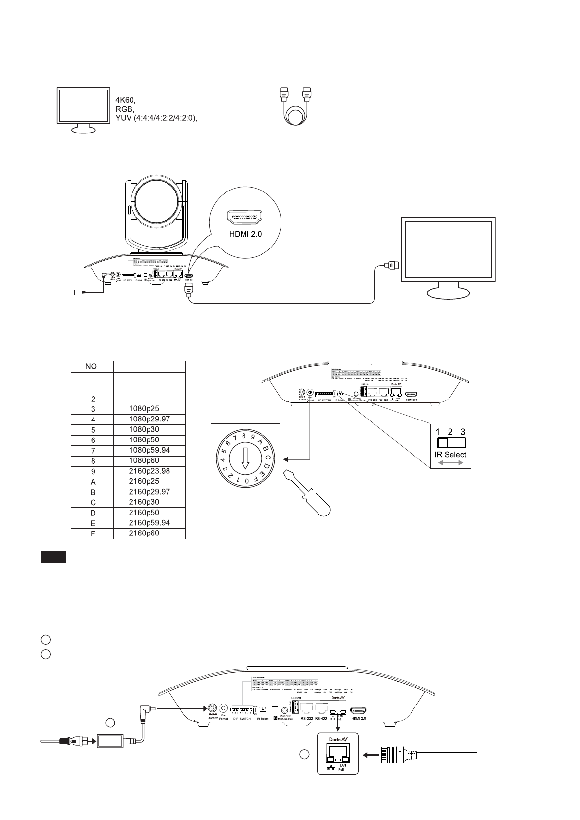
Cat 6 Network Cable,POE PoweredCat6 Network CableFront SideBack SideGroup ARS422 VISCA PortPTZ KeyboardController (Optional)++DanteControllerVideo - Network ViewFileDevicesViewHelpx③ Subscribe Channel on Dante ControllerRS-422 Rs422 channel needs to be subscribed in the Dante controller for remote control. Please refer to the keyboard controller's product manual for detail.You can also use the infrared remote control to remotely control the camera through the DanteAV decoder.For detailed IRremote operation instruction, please refer to camera product manual.Note: The camera should be powered off prior to changing the DIP switch setting. When there are multiple DanteAV camerasinvolved, refer to the table above for unique VISCA address to each camera. Up to seven unique address can be assigned to cameras at any given time.② Camera VISCA Address, Communication Protocol, and Baud Rate Settings++Example: For VISCA ID 1 with RS422 Protocol and 9600 baud rate then set the DIP switch (1-8) to ON, OFF, OFF, OFF, OFF, ON, OFF, ON position.7
Cat6 Network Cable,POE Powered
Dante AV Decoder++++
++++++
DanteControllerVideo - Network ViewFileDevicesViewHelpRoutingDevice InfoClock StatusNetwork StatusEventsPrimaryLeaderClock:D220-0225a2?Filter Tra ns mitter sFilter R eoeive rsReceivers(2)_+_D10H-02263cD220-0225a2RS-422
Transmitters(2)D10H-02263cUSBIRRS-422D220-0225a2HDMILeftRight
xHDMILeftRightCenterLFESoreenLeftSurroundRight SurroundLeftCenterRightCenterUSBRS-422IR_
_+__
____
RS-422
Check to subscribe for controlRS-422

2082 TECHNOLOGY LLC dbaBOLIN TECHNOLOGY
This manual suits for next models
2
Table of contents
Other Bolin Technology Media Converter manuals
Popular Media Converter manuals by other brands

Sennheiser
Sennheiser MobileConnect quick guide

RBH Sound
RBH Sound H485-USB manual

Advantech
Advantech SSPBM-K80-BTE Installation and operating manual

SignaMax
SignaMax I-200 Series quick start guide

Dexing
Dexing NDS3556 Series quick start guide

Transition Networks
Transition Networks SSDTF1011-105 user guide