Bolin Technology Visca VCC-BL-VNS-07202020 User manual

1
Visca Over IP
To
Serial Control
Converter
USER MANUAL
VERSION: VCC-BL-VNS-07202020
© 2020 Bolin Technology

2
Contents
IMPORTANT INFORMATION ..................................................................................................................................................3
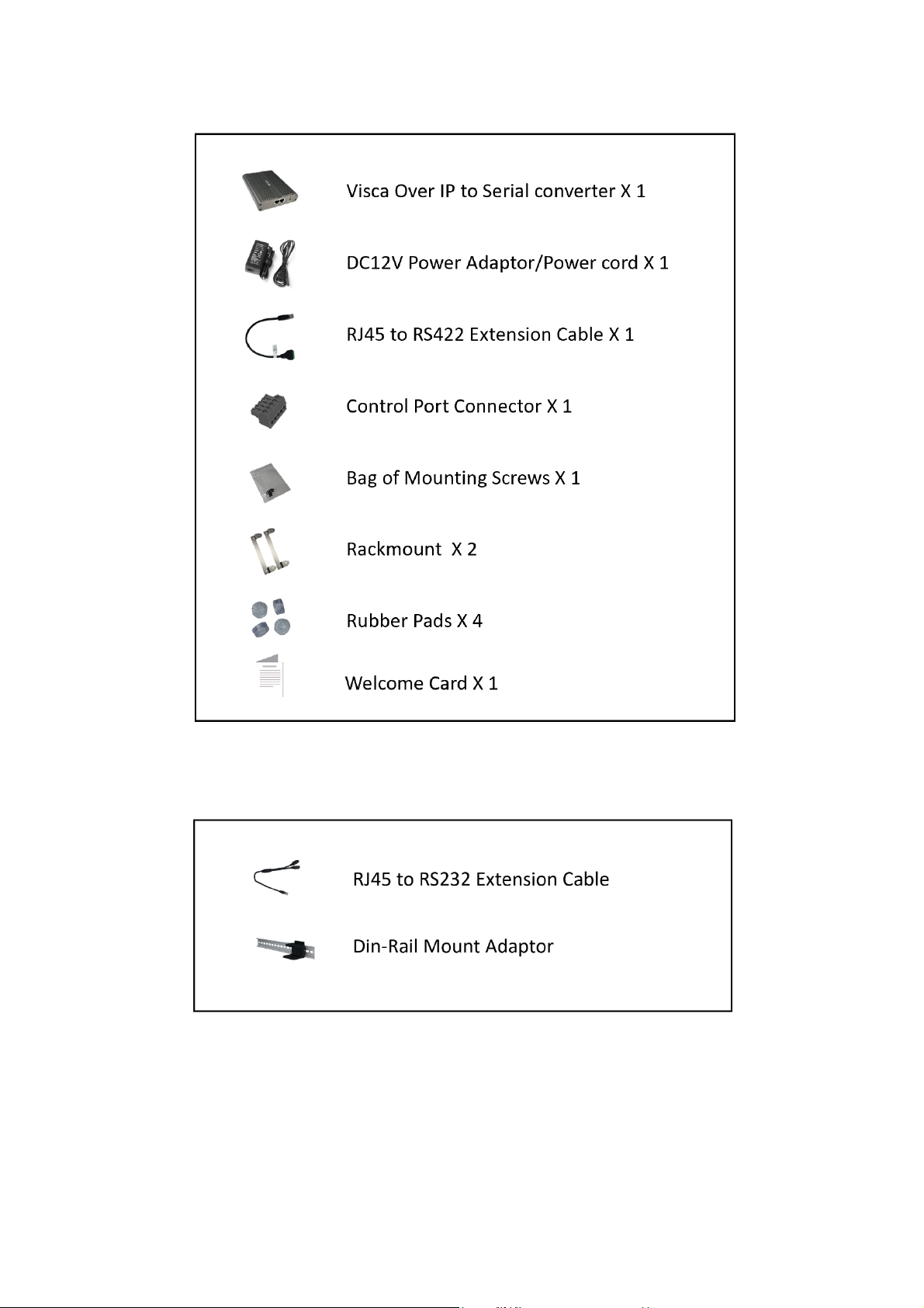
WHAT’S IN THE BOX ..............................................................................................................................................................5
OVERVIEW ............................................................................................................................................................................6
MODEL NUMBERS ............................................................................................................................................................................. 6
FEATURES ........................................................................................................................................................................................ 6
VISCA OVER IP SERIAL CONTROL CONVERTER ........................................................................................................................7
SYSTEM CONFIGURATION......................................................................................................................................................8
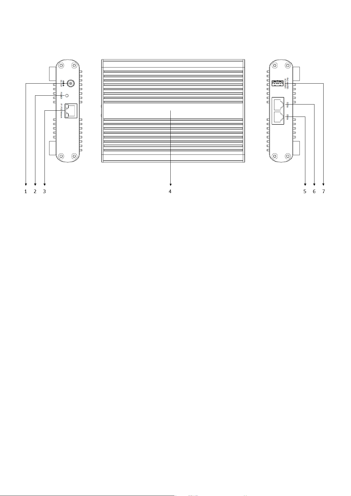
PORT DIAGRAM................................................................................................................................................................................. 8
POWER............................................................................................................................................................................................ 9
...................................................................................................................................................................................................... 9
VISCA OVER IP CONTROL .......................................................................................................................................................9
VISCA OVER IP NETWORK CONFIGURATION......................................................................................................................................... 10
CONNECTION .................................................................................................................................................................................. 10
RS232 SERIAL CONTROL VIA VISCA OVER IP ......................................................................................................................................... 11
RS422 SERIAL CONTROL VIA VISCA OVER IP ......................................................................................................................................... 12
CONNECTION FOR CONTROLLING SONY SERIAL CONTROL PTZ CAMERA...................................................................................................... 13
FIRMWARE UPGRADE..........................................................................................................................................................14
UPGRADING MCU FIRMWARE ........................................................................................................................................................... 14
UPGRADE VIA IP.............................................................................................................................................................................. 14
USER QUICK NOTICE GUIDE .................................................................................................................................................15
NETWORK CONNECTION......................................................................................................................................................16
LOGIN PREPARATION........................................................................................................................................................................ 16
CHECK BEFORE LOGIN ....................................................................................................................................................................... 16
LOGGING IN TO THE WEB INTERFACE...................................................................................................................................17
NOTE: FORGOT PASSWORD?............................................................................................................................................................ 17
IP FINDER TOOL: ............................................................................................................................................................................. 17
NETWORK-NETWORK SETTING-NETWORK............................................................................................................................................ 18
NETWORK-NETWORK SETTING-PORT .................................................................................................................................................. 18
NETWORK-NETWORK SETTING-VISCA OVER IP................................................................................................................................... 18
SYSTEM-SYSTEM SETTING-DEVICE...................................................................................................................................................... 19
THIS SETTING PAGE IS TO GET THE BASIC PRODUCT INFORMATION OF THE CAMERA.................................................................... 19
SYSTEM-SYSTEM SETTING-TIME ......................................................................................................................................................... 19
SYSTEM-SYSTEM SETTINGS-MAINTENANCE .......................................................................................................................................... 20

3
Operating Instructions
Thank you for purchasing Bolin product. If there are any questions, please contact the authorized dealer.
Before operating the unit, please read this manualthoroughly and retain it for futurereference.
Copyright
Copyright 2015-2020 Bolin Technology all rights reserved. No part of this manual may be copied, reproduced,
translated, or distributed in any form or by any means without prior consent in writing from our company.
Trademark Acknowledgement
and other Bolin's trademarks and logos are the property of Bolin Technology Other trademarks,
company names and product names contained in this manual are the property of their respective owners.
IMPORTANT INFORMATION
Legal Notice
Attention:
To ensure account security, please change the password after your first login. You are recommended to set a
strong password (no less than eightcharacters). Password login does not apply to some models that do not
need password login.
The contents of this document are subject to change without prior notice. Updates will be added to the new version
of this manual. We will readily improve or update the products or procedures described in the manual.
Best effort has been made to verify the integrity and correctness of the contents in this document, but no statement,
information, or recommendation in this manual shall constitute formal guarantee of any kind, expressed or implied.
We shall not be held responsible for any technical or typographical errors in thismanual.
The product appearance shown in this manual is for reference only and may be different from the actual
appearance of yourdevice.
This manual is a guide for multiple product models and so it is not intended for any specific product.
In this manual, the illustrations of displayed interface, parameters displayed, drawings and value ranges may vary
with models. Please see the actual product for details.
Due to uncertainties such as physical environment, discrepancy may exist between the actual values and reference
values provided in this manual.
Use of this document and the subsequent results shall be entirely on the user’s own responsibility.
Safety Information

4
WARNING!
Installation and removal of the unit and its accessories must be carried out by qualified personnel. You must
read all of the Safety Instructions supplied with your equipment before installation andoperation.
Warnings:
•If the device does not work properly, please contact your dealer. Never attempt to disassemble the device
yourself. (We will not assume any responsibility for problems caused by unauthorized repair or
maintenance.)
•This installation should be made by a qualified service person and should conform to all the local codes.
•When shipping, the device should be packed in its originalpackaging.
•Make sure the power supply voltage is correct before using the device.
•Do not drop the device or subject it to physicalshock.
Maintenance Precautions:
•If there is dust on the surface, remove the dust gently using an oil-free brush or a rubber dust blowing
ball.
•If there is grease or a dust stain on the surface, clean the surface gently using anti-static gloves or an
oil-free cloth. If the grease or the stain still cannot be removed, use anti-static gloves or an oil-free
cloth dipped with detergent and clean the surface gently until it is removed.
•Do not use organic solvents, such as benzene or ethanol when cleaning the surface.
Regulatory Compliance
FCC Part 15
This equipment has been tested and found to comply with the limits for digital device, pursuant to part 15 of
the FCC Rules. These limits are designed to provide reasonable protection against harmful interference when
the equipment is operated in a commercial environment. This equipment generates, uses, and can radiate
radio frequency energy and, if not installed and used in accordance with the instruction manual, may cause
harmful interference to radio communications. Operation of this equipment in a residential area is likely to
cause harmful interference in which case the user will be required to correct the interference at his own
expense.
This product complies with Part 15 of the FCC Rules. Operation is subject to the following twoconditions:
This device may not cause harmfulinterference.
This device must accept any interference received, including interference that may cause undesired operation.
LVD/EMC Directive
This product complies with the European Low Voltage Directive 2006/95/EC and EMC Directive
2004/108/EC.
WEEE Directive–2002/96/EC
The product this manual refers to is covered by the Waste Electrical & Electronic Equipment
(WEEE) Directive and must be disposed of in a responsible manner.

5
WHAT’S IN THE BOX
Accessories (Optional)

6
Overview
Model Numbers
This user guide is suitable for the following models:
•BL-VNS-1
Features
•Hardware Visca over IP solution
•Support 802.3at PoE+
•Provide Serial RS-232, RS-422/485 control over Ethernet by Visca over IP protocol
•MCU firmware upgradable via USB port
•IP firmware upgradable via IP web interface
•Power: DC 12V Power input

7
Visca over IP Serial Control Converter
1. 12V DC Power Port
Connect include 12V DC power adaptor and cord
2. Power LED Indicator
Turns red when the device is boot up completely.
3. RJ45 Port for IP/PoE Network
Used for IP network connection, support PoE power supply (IEEE 802.3at)
4. Heat-sink surface panel
All aluminum body for quick heat dissipation
5. RS-422 Control Port
Use RJ45 to RS-422 extension adapter cable or make CAT6 cable to remotely control PTZ camera.
6. RS232 Control Port
Use RJ45 to RS-232 extension adapter cable or make CAT6 cable to remotely control PTZ camera
7. USB 2.0 Port
Used for MCU firmware upgrade only.

8
System Configuration
Port Diagram

9
Power
•Use only the DC power adaptor (JEITA type4) supplied with the unit. Do not use any
otherDC power adaptor.
•If using POE to power the camera, PoE+(IEEE802.3at) is supported
•Ensure that the POE power source has sufficient power budget to power the camera, or some features may not
function properly.
VISCA over IP Control
With VISCA over IP function, you can control the camera using VISCA protocol on a controller equipped with
IP communication capabilities via LAN. This converter converts control signal via Visca Over IP to Serial
control signal to control PTZ camera with only serial control functionality.

10
The communication specifications of VISCA over IP are followings:
•Interface: RJ-45 10/100M
•Interface protocol: IPv4
•Transport protocol: UDP
•IP address: 192.168.0.13 By default
•Port: 52381
VISCA over IP Network Configuration
Re-assign the camera
The default information of the IP camera is following:
•Static IP: 192.168.0.13
•Subnet mask: 255.255.255.0
•Gateway: 192.168.0.1
•VISCA over IP control port: 52381.
The camera IP address needs to be assigned to the IP address that works with your local network.
Controlling via VISCA over IP
•Connect the network port on the camera to the network switch.
•Set the IP address and other network information appropriately to communicate on your network
•Connect the VISCA over IP-compatible controller to the network
•Configure the controller to access the camera’s IP address and VISCA over IP port
•The IP port within on your control must be set to 52381 to communicate with the camera.
•Select VISCA protocol on your IP control device.
Recommended way to re-assign the IP address:
1. Create a local network within which the camera and your PC/Laptop are connected.
2. Install and run the IP-FINDER tool (You can contact Bolin Technical support team for tool requirements)
3. The IP-FINDER can find the camera IP address, which is the default :192.168.0.13
4. Click the search button, select the camera you want to Assign IP address, edit the IP address to the one that matches your
local network credential.
5. Once the IP address has been changed successfully, you can access the IP camera via your local network.
Note
How to re-assign the IP address to the camera, please refer to user manual Part Two-IP Camera user
guide.
Connection

11
RS232 serial control via Visca Over IP
NOTE:
•This Visca Over IP converter does not support Daisy Chain multiple camera control.
•This diagram shows how to make the connection correctly, for you to make the control with the controller and the
camera successfully, please refer to your controller and camera user guides.
1. Use extension cables included RJ45 to RS422/232 Phoenix terminal contact adaptor to make RS232 connection for your
camera.
2. You can use CAT5/6 T-568B Standard Ethernet cable direct connect between the camera and the converter to make RS232
connection by following the pin definition below:
Important:

12
•The baseline cable standard for HD/4K systems is Cat5e. Signal
greater distances can be achieved by using Cat6e or higher above as
Cat7, which have thicker copper cores for easier signal transfer.
•Whichever network cable type you choose, ensure that the main wiring
is ‘solid core’, not ‘patch’ cabling.
•Terminate the cabling using RJ45 connectors to the 568B wiring
standard, shown as below:
3. Use extension cables RJ45 to RS232 8 pin Mini Din adaptor (Sold separately) to make RS232 connection for your camera
RS422 serial control via Visca Over IP
NOTE:
•This Visca Over IP converter does not support Daisy Chain multiple camera control.
•This diagram shows how to make the connection correctly, for you to make the control with the controller and the
camera successfully, please refer to your controller and camera user guides.
1. Use extension cables RJ45 to RS422 Phoenix connecter adaptor included to make RS422 connection for your camera.

13
2. You can use CAT5/6 T-568B Standard Ethernet cable direct connects between the camera and the converter to make RS422
connection by following the pin definition below:
Connection for controlling SONY serial control PTZ camera
NOTE:
•It requires a special firmware to control SONY serial PTZ camera. Please consult your seller to gain the correct
version of the firmware.
•This Visca Over IP converter does not support Daisy Chain multiple camera control.
•This diagram shows how to make the connection correctly, for you to make the control with the controller and the
camera successfully, please refer to your controller and camera user guides.
1. Use extension cables RJ45 to RS422 Phoenix connecter adaptor included to make RS422 connection for your camera.

14
Firmware Upgrade
Upgrading MCU Firmware
MCU Firmware can be upgraded by following these steps:
1. Load the .bin file onto a flash drive (Formatted as
FAT32), and rename the file “HD20.bin”
2. With the camera powered off, insert the flash
drive to the USB port on the back panel of the
camera
3. Apply power to the camera
After power on the converter box, wait for three minutes,
the new firmware will be upgraded successfully. There is no LED indicator to show the upgrade progresses.
The verify is the new firmware is upgraded correctly or not, go to the converter web GUI, System, Maintenance to check
the firmware version.
NOTE:
The firmware upgrade process is intended to be performed under the supervision of a BOLIN-Authorized
repair technician. For assistance with this, please contact your authorized BOLIN Technology dealer, installer,
or integrator. BOLIN Technology Technical Support can also be reached for assistance with this process
Upgrade via IP
You can upgrade device IP Firmware via IP.
How to make Firmware upgrade for IP, please refer to User Manual Part Two.

15
Part Two
Bolin IP web interface
User Quick Notice Guide
This Visca-Over-IP Serial Control Converter does not have video IP streaming functionality.
All features related to IP video streaming are not functional.
IP feature is limited with the web GUI.
This Quick Guide is for Bolin FHD/4K Dual Output PTZ camera IP web interface use. Please read it carefully before you start
using your camera and follow the instruction to effectively use the camera/IP device, or check it when you are having some trouble
with IP video streaming and IP control.
Please contact Bolin technical support team at www.bolintechnology.com if you have more questions or having trouble that is not
included in this guidance.
This paper is part of product user guide, please refer to our product user manual if you have questions regarding how to use the
camera. User manual can be downloaded at Bolin website.
Note:
•Currently the IP camera only supports Internet Explorer 11 browser, other browsers compatibility will be available
via future firmware upgrading.
•It will be required to download the Controls (VideoPlugin) for the first time login, please click the download link
and follow the prompts to download and install it.
•After the VideoPlugin has been installed, you may be prompted to update the VideoPlugin, please uninstall the
old version of Plugin before you download and install the new version of Plugin.
Login
The default static IP address of the camera is
192.168.0.13, and default subnet mask is
255.255.255.0. Please change your PC/laptop’s IP
address to located within the same subnet as the
camera.
The login procedure as following:
•Open the Internet Explorer 11 browser, running
it as Administrator
•Browser to the login page by entering
http://192.168.0.13:8080 (must entering the port
8080)
•The default user name is admin, password is
admin
NOTE: If the camera IP address has been modified, the login page URL should be http://x.x.x.x:8080 (x.x.x.x is the correct IP
address of the camera)
IP Firmware Update
You have to add the camera IP interface URL to the IE11 browser’s Trusted Sites before to start firmware update, otherwise, you
will be prompted that the firmware file cannot be opened.
•Click Setting button of IE11 browser, access to Internet Option > Security page.
•There has Trusted Sites option, click and add the URL to the list.
•Please don’t check the “Require server verification (https:) for all sites in this zone” option box.
•Go back to maintenance page and now you can start the firmware update.
NOTE: The firmware update including two steps:
•The First step is to select the firmware file and upload it to the camera IP module, there will be a percentage progress bar
display to indicate the upload status on the page.
•The Second step is the firmware burning and updating, there is no progress bar prompt in this step, the burning and

16
updating process takes about 3 minutes. After the update is successful, the page will prompt “Upgrade is successful…”,
please click OK button to reboot the camera.
•Please don’t power off or reboot the camera during the whole updating process, until the page prompt “Upgrade is
successful…”
Network Connection
Before accessing a network camera (also known as IP Camera or IPC) from a PC, you need to connect the
network camera to the PC directly with a network cable or via a switch or router.
Use a Shielded Twisted Pair (STP) cable to connect the network interfaces of the network camera and the PC.
Use Shielded Twisted Pair (STP) cables to connect the network interfaces of the camera and the switch or router.
Login Preparation
After you have completed the installation in accordance with the quick guide, connect the camera to power to boot
it. After the camera is booted, you can access the camera from a PC client using Internet Explorer or a Video
Management System (VMS).
The following uses Internet Explorer 11 on a Microsoft Windows 10 operating system as an example.
Check before login
⚫
The camera is powered on and connected to the network switch
⚫
The camera’s IP address is located within the same subnet as the PC
⚫
The PC is connected to the network switch
⚫
The PC’s IP address is located within the same subnet as the camera
⚫
The PC is installed with Internet Explorer 8.0 or higher (Internet Explorer 11 recommended)
⚫
Use default video format setting or set the camera video format to 1080P30 or 1080P25 using RS485
keyboard (Refer to camera setting menu).

17
Logging in to the Web Interface
The default static IP address of the camera is 192.168.0.13, and the default subnet mask is 255.255.255.0
The following uses Internet Explorer as an example to describe the login procedure.
1. Browse to the login page by entering correct IP address plus port number 8080 (e.g. http://192.168.0.13:8080 ) of
your camera in the Internet Explorer address bar.
2. Enter the username and password, and then click
Login. The default username admin and password
admin
3. If this is your first timing login in to the camera web
interface, you have to download and install the
Control plug-in, click “Click Here To Download
Controls” link to start the download.
4. Follow system prompts and install the “VideoPlugin-
win32-4.1.0.10512”. You need to close your browser
and reopen it again to complete the installation.
5. Click Allow to enable the plugin when you re-login
after installed the “VideoPlugin-win32-4.1.0.10512”
•The default password is used for your first login. To ensure account security, please change the password after
your first login. You are recommended to set a strong password (no less than eightcharacters).
•VideoPlugin version may different in different camera version.
•If you login with Remember Password selected, you do not need to enter the password each time when you login,
to ensure security, you are not advised to select Remember Password.
NOTE: Forgot Password?
•A message will pop up, which
reads: “Please contact the
manufacturer for disposal!”
•You can download the IPCSearch
tool from the
www.bolintechnology.com
•Unzip the file and configure your
laptop in the same subnet as
camera’s, run the IPCSearch tool
and you will get the camera
connection with your IPCSearch
tool, click this camera bar (not to
tick off the selection box) in the list,
and then click Forgot Password
button which is in the bottom right corner, a key number will display in the pop-up window
•Please copy this key number and send it to us, you can contact us at: [email protected]
•A BOLIN Technology Support team will provide a temporary password that is only valid for 24 hours, which can
be used to log in to the camera to create a new password. Please use the temporary password within 24 hours,
you will have to repeat the above process to get a new temporary password if it gets expired.
IP Finder Tool:
•Running the IP Finder Tool on your laptop/pc, it will automatically get the list of all cameras that located in the
same network.
•You can get the MAC address, IP address, Camera name, Camera model, Serial number etc. of the cameras.
•IP Finder Tool will help you to get the IP address when you forget the camera IP.

18
Network-Network Setting-Network
The network tab is where the user is able to configure the following:
•DHCP options
oDHCP –An IP address will be dynamically
assigned to the camera from the gateway (router)
oStatic IP –The user will enter / define the IP
address
•IP Address
oDefault IP address is 192.168.0.13
•Subnet Mask
oDefault mask is 255.255.255.0
•Default Gateway
oDefault gateway is 192.168.0.1
•Preferred DNS
•Alternate DNS
•MAC Address
oFixed, can’t be modified.
Network-Network Setting-Port
This setting page is to specify which ports the camera will use to communicate with the following protocols:
oTCP Port:
o1 to 65535 adjustable
oUDP Port:
o1 to 65535 adjustable
oRTSP: Default 554
oRTSP is the protocol used to pull real-time
video over the network (using VLC Player or
other network video-compatible software)
oChanging this port number will change the way
the RTSP video can be viewed. Most RTSP
streaming software uses port 554 by default,
therefore it is not recommended that this port
number be changed.
oURL for receive RTSP streaming is: rtsp://IP:554/PSIA/Streaming/channels/0
oHTTP: Default 8080
oHTTP is the protocol used to access the web interface.
oChanging this port number will require the user to specify the port number when entering the IP address
to the web browser.
oFor example, if it is changed to 85, the IP address will need to be entered as follows in order to access
the web interface: http://192.168.0.13:85
Network-Network Setting-VISCA OVER IP
1. Check the Enable option
2. The port is fixed as 52381
3. Click Apply button to make the setting available

19
System-System Setting- Device
This setting page is to get the basic product information of the
camera.
•Device Name
oYou can set a name to this camera
•Model Number
oThe specific model of this camera
•Product Serial Number
oThe serial number of this camera, each serial
number is unique and fixed, can’t be modified.
•Encoder Version
oThe current encoder version running on this
camera
•MCU Version
oThe current MCU version running on this camera
•Web Plugins Version
oThe current web interface plugin version running on this camera
You may be asked to provide above information by Bolin technical team for any possible technical support cases.
System-System Setting-Time
This interface allows user to configure the date / time settings of the camera
•System Time
oYou can check the Sync with Computer Time
option and synchronize the camera operation time
with your PC time system.
•Date Format
oTwo formats selectable
oY-M-D or D/M/Y
•Time Format
oTwo formats selectable
o24H or 12H standard
•Time Zone
oWEST 12 to EAST 12 selectable
oPlease select the correct time zone for your
location
•Network Time Sync
oCheck the Enable option
oInput the time sync server address, port number
oSelect refresh time option, it has 10 Min, 30Min, 1 Hour, 1 Day selectable.
After done the configuration, please remember to click Apply button to make the setting activated. You also can click
Default Setting to restore settings to default if you want to.

20
System-System Settings-Maintenance
The Maintenance tab under the System Setting section can be used to perform the following functions:
•Firmware Update
You can upgrade IP Encoder software and
FPGA software via this Firmware Update
feature.
oTwo types of firmware can be
upgraded from this section:
▪Firmware for IP encoder. The
name of the file shown as
“BC9-IP-xxxxxx.dat”
▪Firmware for FPGA. The
name of the file shown as
“BC9-FPGA-xxxxxx.dat”
oA firmware file can be obtained from BOLIN Technology website: www.bolintechnology.com
NOTE:
oFor MCU version upgrade, please refer to “Upgrading MCU
Firmware” in User Manual Part 1.
NOTE: You need to add the camera IP interface URL to the IE browser’s Trusted
sites before to start upgrade, otherwise, you will be prompted that the file cannot be
opened.
oClick Setting button of IE browser, access to Internet Option>
Security page;
oThere has Trusted sites option, click and add the URL to the list;
oPlease don’t check the “Require server verification (https:) for all
sites in this zone” option box;
oGo back to maintenance page and now you can start the upgrade;
•Device Restart
oSoft reboot, only restart the IP
encoding board. When there is a
problem with the IP interface or
the IP output, you can try to
restart the encoding board;
oSupports auto restart and
manual restart mode;
oAuto Restart can be configured as Never, Per day, Per week, Per month, what you have to do is just
select an option and click Enter button to make it available.
oManual Restart is just to click the Manual Restart Device button, and the camera encoding board will
going to restart immediately.
Table of contents
Other Bolin Technology Media Converter manuals