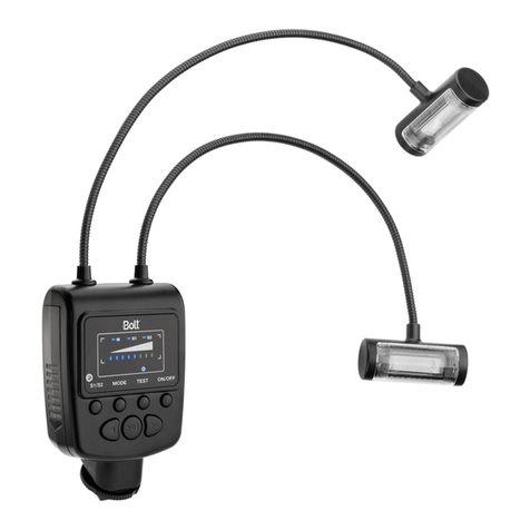
Bolt VM-110 User manual

RING LIGHT
VM-110 LED MACRO RING LIGHT
User Manual

2 |Introduction
Thank you for choosing Bolt.
Thank you for choosing the Bolt VM-110 LED Macro Ring Light. This LED light combines a compact design with
versatile features to give you both ease of use and creative lighting control. It’s great for shooting close-ups and
even portraits at close range. Among the benefits you’ll enjoy:
• Six levels of brightness adjustment
• Left- and right-only illumination modes
• Flash mode
• Automatic power-saving function

Table of Contents |3
Table of Contents
Precautions ............................................................................................................................................................4
Contents................................................................................................................................................................. 7
Overview ................................................................................................................................................................8
Battery Installation ................................................................................................................................................ 11
Mounting the VM-110.............................................................................................................................................13
Using the Diusers................................................................................................................................................16
Turning On the VM-110 and Firing a Test...............................................................................................................18
Operation Modes..................................................................................................................................................20
Troubleshooting ...................................................................................................................................................22
Specifications .......................................................................................................................................................23

4 |Precautions
Precautions
⚠⚡
• Before using this product, please thoroughly read the
following safety notices to ensure safe use and help
prevent damage to your flash or injury to yourself and
others.
• Do not fire the flash at close range directly into the eyes
of people or animals. This can cause damage to the
retina and may even lead to blindness.
• To avoid overheating and damaging your flash unit,
please wait for at least ten minutes after twenty-five
continuous flashes at full power.
• Do not disassemble or attempt to repair this product
yourself. There are high-voltage components inside that
can produce a hazardous electric shock.
• Keep this product and its batteries out of the reach of
children.
• Use only the power sources specified in this manual.
• Always switch the flash o before changing the batteries.
• Always install batteries of the same type, brand, and
age. Do not combine dierent types or brands, or old
and new batteries. This can cause the batteries to leak,
overheat, or explode. Install the batteries in the proper
orientation, according to the indicator in the battery
chamber. Installing batteries in the reverse orientation
may cause them to leak, overheat, or explode.
• Do not clean this product with agents containing
corrosive or flammable substances such as paint thinner,
benzene, or nail-polish remover.

Precautions |5
• Do not use or store this product in flammable conditions
(such as environments containing flammable gases or
liquid chemicals). This can damage the flash, start a fire,
or cause an electric shock.
• This product is not water resistant. Keep it away from
rain, snow, humidity, and general moisture.
• If you detect a burning smell, smoke, or excessive heat
coming from the flash, immediately stop operation
and remove the batteries to prevent the product from
igniting or melting.
• Do not drop or otherwise cause a strong physical impact
to this product, as this can cause a malfunction that may
cause it to explode or ignite.
• Should the product sustain physical damage, do not
touch any exposed interior metal parts. If touched, they
may generate an electric shock or cause a malfunction.
Promptly remove the batteries, and take the product to
an authorized service center for repair.
• For long-term storage, remove all batteries from this
product to prevent the product from igniting or leaking
corrosive liquids.
• Do not store or use this product at temperatures above
149°F (65°C).

6 |Precautions
• Keep the metal contacts in the battery compartment
clean and free of corrosion and dirt. Do not touch them
with your fingers. Corrosive elements on the contacts
can damage this product and prevent it from functioning
properly. Contacts may be cleaned with isopropyl
alcohol on a cotton swab.
• Dispose of used batteries properly. Never heat them or
throw them into a fire, as this can cause the batteries to
leak corrosive liquids, generate heat, or explode.
• Images are for illustrative purposes only.

Contents |7
Contents
• VM-110 LED Macro Ring Light
• 4 diusers (clear, frosted white, blue, and amber)
• 8 adapter rings (49, 52, 55, 58, 62, 67, 72, and 77mm)
• Stand / tripod mount

8 |Overview
LED Ring Light
1 LED array
2 Adapter ring locks
3 Diuser mounting indicators
4 Cable
Power Control Unit
5 LCD
6 Battery compartment cover
7 Mode button
8 Pilot button
9 Left navigation button
10 Mounting foot
11 Light button
12 Power button
13 Set button
14 Right navigation button
15 Locking wheel
Overview

Overview |9
3
6
1
2
4
8
9
11
12
13
14
7
10 15
5

10 |Overview
LCD
16 Battery level indicator
17 Light mode
18 Flash mode
19 Left mode
20 Right mode
21 Dot indicator
22 Power output level indicator
23 Power output value
17 18 19 20
21
23
16
22

Battery Installation |11
Battery Installation
The VM-110 can be powered by four AA batteries of several types:
• Lithium (1.5 V)
• Nickel-metal hydride (Ni-MH) (1.2 V)
• Alkaline (1.5 V)
Note: For the longest battery life, lithium or Ni-MH batteries are recommended.
To install batteries, make sure the VM-110 is turned o and follow these steps:
1. Press on the battery compartment cover and slide it in the direction of the arrow to open it.
2. Insert batteries in the orientations indicated by the illustrations inside the compartment.
3. Close the battery compartment cover by pressing and sliding it into place, in the opposite direction of the
arrow on the cover.

12 |Battery Installation
Important! When battery power is low, the battery level indicator will blink on the LCD. Replace all four batteries
at the same time. Do not mix battery types or brands, or use old and new batteries together.
1 2 3

Mounting the VM-110 |13
Mounting the VM-110
The VM-110 has two main components, the power control unit and the LED ring light. The power control unit
mounts onto your camera’s hot shoe mount, and the LED ring light mounts onto your camera’s lens via one of
the included adapter rings. There are eight adapter rings included: 49, 52, 55, 58, 62, 67, 72, and 77mm.
To mount the power control unit on your camera, make sure the
VM-110 is turned o and follow these steps:
1. Rotate the locking wheel counterclockwise to loosen it.
1

14 |Mounting the VM-110
1. Determine what size adapter ring will fit your camera lens; the
engraving on the ring should match your lens’s filter thread.
2. Align the adapter ring with the thread on the inside of the lens,
and screw it on until secure. Do not overtighten.
3. Press and hold the adapter ring locks while mounting the ring
light onto the adapter. Make sure that the Bolt logo is on the
bottom of the ring light and facing away from the camera.
2. Slide the mounting foot
all the way into your
camera’s hot shoe.
3. Rotate the locking
wheel clockwise until
secure.
To mount the LED ring light on your camera, follow these steps:
2 3
23

Mounting the VM-110 |15
To dismount the VM-110 from your camera, make sure that it is turned o and follow these steps:
1. Press and hold the adapter ring locks to release the LED ring.
2. Rotate the locking wheel counterclockwise to release the power control.
3. Slide the mounting foot out of your camera’s hot shoe.
4. If desired, remove the adapter ring from your lens.
Mounting the VM-110 power control on the included stand:
You can mount the VM-110 power control unit on the included stand in the same way you would mount it on
your camera. This allows you to set it on a flat surface or to attach it to a tripod head, light stand, or clamp that
has a compatible 1/4"-20 screw mount. Using your VM-110 in this manner will free up your camera’s hot shoe.

16 |Using the Diusers
Using the Diusers
The VM-110 comes with four diusers that modify the light output:
clear, frosted white, blue, and amber. The frosted white diuser will
produce a more diused light than the clear one. The blue and amber
diusers will cool and warm the light, respectively. Note that you will
lose a bit of light with the blue and amber diusers.
To mount the diuser on your LED ring:
1. Match up the alignment line on the diuser with the OPEN
alignment line on the LED ring.
2. Fit the diuser onto the LED ring and rotate it so the alignment
line on the diuser matches up with the CLOSE alignment line on
the LED ring.
CLOSE
CLOSE
1
2

Using the Diusers |17
To remove the diuser, rotate it so that the indicator matches up with the OPEN alignment line. The diuser can
then be removed.
Tip: Using the VM-110 without any diuser in place will result in the maximum brightness, but the light will also
be the least soft.

18 |Turning On the VM-110 and Firing a Test
Turning On the VM-110 and Firing a Test
To turn the VM-110 on, press and hold the power button until the LCD on the power control unit turns on. To fire
a test, press the PILOT button.
Important! Some lenses have front elements that rotate during autofocusing. In such a case, we recommend
using manual focus to prevent any possible damage to your lens or camera.
Automatic power-saving function: After thirty minutes of inactivity, the VM-110 will automatically enter power-
saving mode to conserve battery life. To reactivate the VM-110, press the SET button. During long periods of
inactivity, it is recommended that you use the power button to turn the LED o completely.
LCD illumination: When you turn on the VM-110 or press any button, the LCD will be illuminated for about twenty
seconds.

Turning On the VM-110 and Firing a Test |19
Battery level indicator: The battery level
indicator on the LCD shows the remaining
battery power.
LCD Display Status Battery Level
70%–100%
40%–69%
10%–39%
0%–9%

20 |Operation Modes
Operation Modes
Light Mode
During Light mode, the light will be on continuously. This is ideal for seeing exactly where the light will fall, as
well as for shooting video. Press the LIGHT button to turn on the LEDs for constant lighting. The dot indicator on
the LCD will switch to Light mode.
Flash Mode
To save battery power, you can engage the flash mode so the LED turns on for approximately half a second when
the camera’s shutter is released. To engage the Flash mode, press the MODE button repeatedly until the dot
indicator on the LCD switches to Flash mode.
When switching to Flash mode from Light mode, the power level indicator may rise to a higher level. This
happens when the battery power is very low and indicates that the batteries will have a longer eective life in
Flash mode. Note that the flash mode will work only if the control unit is mounted on the camera’s hot shoe.
Other manuals for VM-110
1
Table of contents
Other Bolt Camera Flash manuals
Popular Camera Flash manuals by other brands

BUFF
BUFF Einstein E640 User manual/operation instructions
Nissin Digital
Nissin Digital i400 instruction manual
Gisteq
Gisteq Flashmate II N101C user manual
Toshiba Photo Products Co., Ltd.
Toshiba Photo Products Co., Ltd. 414 Instruction
Metz
Metz MECABLITZ 48 AF-1 digital operating instructions
Godox
Godox V1 N manual
