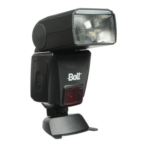
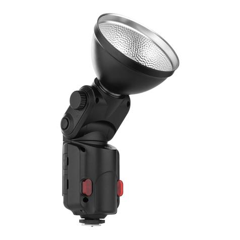
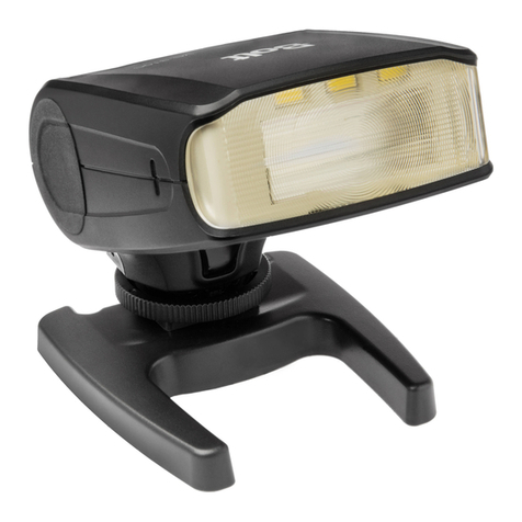
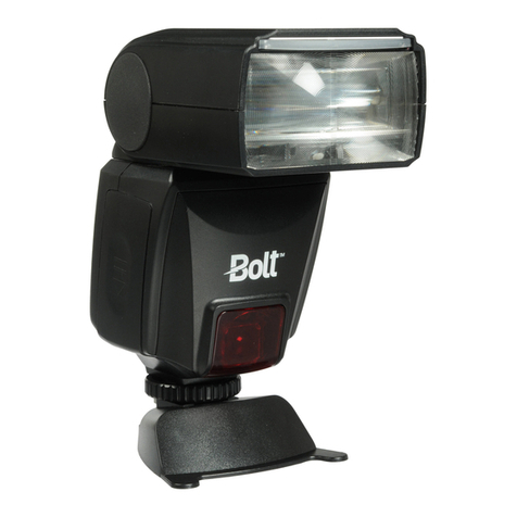
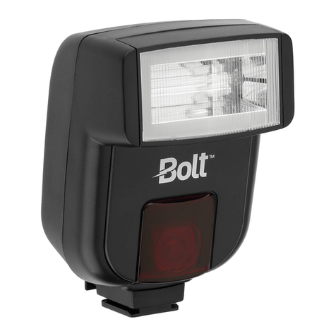
Bolt VM-1000C User manual

VM-1000
TTL MACRO FLASH SET
User Manual

2 |Introduction
Thank you for choosing Bolt.
The Bolt VM-1000 is a full-featured wireless macro
flash for your Nikon, Canon, or Sony camera. This
advanced digital flash system puts creative control
in your hands with a broad range of automatic and
manual features. It can be used to illuminate close-up
subjects with multi-flash setups and flexible wireless
communication.
Enjoy automatic TTL settings with the ability to use
up to three groups and sixteen channels without
interference. Change auto flash compensation values
or set flash power manually. With the included Macro
Flash Ring, you can use up to four VM-1010 flash units.
You’ll be able to experiment with light and customize
lighting settings to illuminate close-up subjects.
Table of Contents
Precautions ..........................................................3
Contents...............................................................5
Overview ..............................................................6
Battery Installation ............................................. 12
Transceiver and Flash Setup .............................. 14
VM-1010 Flash Settings and Controls................ 20
VM-1020 Transceiver Settings and Controls ......22
Specifications .....................................................32
Troubleshooting .................................................34
Firmware Upgrade .............................................35
FCC Compliance.................................................35

Precautions |3
Precautions
⚠⚡
• Before using this product, please thoroughly read the
following safety notices to ensure safe use and help
prevent damage to your flash or injury to yourself and
others.
• Do not fire the flash at close range directly into the eyes
of people or animals. This can cause damage to the
retina and may even lead to blindness.
• To avoid overheating and damaging your flash unit,
please wait for at least ten minutes after twenty-five
continuous flashes at full power.
• Do not disassemble or attempt to repair this product
yourself. There are high-voltage components inside that
can produce a hazardous electric shock.
• Keep this product and its batteries out of the reach of
children.
• Use only the power sources specified in this manual.
• Always switch the flash o before changing the batteries.
• Always install batteries of the same type, brand, and
age. Do not combine dierent types or brands, or old
and new batteries. This can cause the batteries to leak,
overheat, or explode. Install the batteries in the proper
orientation, according to the indicator in the battery
chamber. Installing batteries in the reverse orientation
may cause them to leak, overheat, or explode.
• Do not clean this product with agents containing
corrosive or flammable substances such as paint thinner,
benzene, or nail-polish remover.

4 |Precautions
• Do not use or store this product in flammable conditions
(such as environments containing flammable gases or
liquid chemicals). This can damage the flash, start a fire,
or cause an electric shock.
• This product is not water resistant. Keep it away from
rain, snow, humidity, and general moisture.
• If you detect a burning smell, smoke, or excessive heat
coming from the flash, immediately stop operation
and remove the batteries to prevent the product from
igniting or melting.
• Do not drop or otherwise cause a strong physical impact
to this product, as this can cause a malfunction that may
cause it to explode or ignite.
• Should the product sustain physical damage, do not
touch any exposed interior metal parts. If touched, they
may generate an electric shock or cause a malfunction.
Promptly remove the batteries, and take the product to
an authorized service center for repair.
• For long-term storage, remove all batteries from this
product to prevent the product from igniting or leaking
corrosive liquids.
• Do not store or use this product at temperatures above
149°F (65°C).

Contents |5
• Keep the metal contacts in the battery compartment
clean and free of corrosion and dirt. Do not touch them
with your fingers. Corrosive elements on the contacts
can damage this product and prevent it from functioning
properly. Contacts may be cleaned with isopropyl
alcohol on a cotton swab.
• Dispose of used batteries properly. Never heat them or
throw them into a fire, as this can cause the batteries to
leak corrosive liquids, generate heat, or explode.
• Images are for illustrative purposes only.
Contents
• VM-1010 TTL Macro Flash (×2)
• VM-1020 TTL Transceiver
• Flash mounting ring
• Transceiver mini stand
• Macro Flash stand (×2)
• Shoe adapters (×2)
• Soft diuser (×2)
• Diuser (×2)
• 9 color gels (×2)
• Gel pouch (x2)
• Padded zippered case
• Lens adapters: 52, 55, 58, 62, 67, 72, and 77 mm

6 |Overview
Overview
Macro Flash VM-1010
1 Group LED indicators
2 Luminance LED indicators
3 Macro TTL LED indicator
4 S1/S2 LED indicators
5 Channel LED indicators
6 Group / < button
7 LED focus assist light / flash test button
8 Set button
9 Power button
10 Channel / > button
11 LED status indicator
12 Battery cover
13 Mounting-foot lock
14 Mounting foot
15 Flash sensor
16 LED assist lamps
17 Diuser notches
18 USB interface
19 Slide release

Overview |7
S1
1/64
A
GROUP
ID 0000
CHANNEL
B C 1 2 3 4
1/32 1/16 1/8 1/4 1/2 1/1
S2
19
13
14
3 16151211 17 18
6 107 8 9
21 54

8 |Overview
Transceiver VM-1020
1 Power button
2 LED focus assist button
3 Flash test LED indicator/button
4 Adjustment dial
5 Info button
6 Mode button
7 Set button
8 Group button
9 LCD
10 1/4-20 socket
11 Hot shoe
12 Link indicator LED
13 Battery compartment button
14 Battery compartment door
15 LED focus assist
16 Mounting foot
17 Collar-lock release button
18 Foot-collar lock
19 USB port
20 2.5 mm shutter-release sync port

Overview |9
12 14 151311 10
1
2
4
5
3
6 9 1916 1817 207 8

10 |Overview
Flash Mounting Ring
1 Ring release button (×2)
2 Flash holder ring
Flash Stand
7 Cold shoe
8 1/4-20 socket
9 Foot mount
Diuser
3 Notch windows
Shoe Adapter
4 Foot mount
5 Locking wheel
6 Mounting foot

Overview |11
1
4
5
6
7
8
3
2
9

12 |Battery Installation
Battery Installation
VM-1010
1. Push and slide out the battery compartment door
in the direction of the arrow.
2. Insert the batteries with the correct polarity
orientation.
3. Slide the battery door closed until it’s secure.
1
2

Battery Installation |13
VM-1020
1. Press the battery compartment button to open
the door.
2. Insert the batteries on top of the release pull,
with the correct polarity as shown inside the
compartment.
3. Close the compartment door until secure.
Note: When the batteries are low on power, the
battery icon will blink. If the batteries are out of
power, the screen displays NO POWER, and the unit
will turn o.
1
2

14 |Transceiver and Flash Setup
Transceiver and Flash Setup
Mounting the Transceiver to a Camera
1. Press the collar-lock release button, and slide the
collar to the left to unlock.
2. Insert the mounting foot into your camera’s hot
shoe.
3. Slide the collar to the right until it clicks and is
locked.
Mounting the Transceiver to a Stand
Mini Stand
1. Make sure the transceiver’s collar lock is in the
unlocked position.
2. Slide the transceiver into the mini-stand’s cold
shoe, and slide the collar to the right until it locks.
3
2

Transceiver and Flash Setup |15
Light Stand
You can mount the transceiver to a light stand, using the mini-stand or transceiver’s 1/4-20 socket.
1. Screw the mini stand on to a light stand using the 1/4-20 mount.
2. Attach the transceiver to the mini-stand’s cold shoe,
and slide the collar lock to the right until secure.
Alternatively, you can screw the transceiver’s 1/4-20
socket to a wide variety of grips and mounting hardware.
Mounting a Flash to the Transceiver
A flash can mount to the transceiver and operate
remotely with TTL functionality, as if mounted directly to
your camera.

16 |Transceiver and Flash Setup
Mounting the Macro Flash
Setting Up the Flash Mounting Ring
1. Choose the lens adapter (52, 55, 58, 62, 67, 72,
or 77 mm) that fits your lens, and screw it onto the
lens’s filter threads.
2. Squeeze the ring release buttons, seat the flash
mounting ring over the lens adapter, and release.
Wiggle the mounting ring a little to make sure it’s
secure.
1
2

Transceiver and Flash Setup |17
3. Seat the flash’s mounting foot into the ring’s flash
holder, and slide the foot lock down to secure.
Use the slide release buttons to adjust the flash’s
postion around the ring.
Mounting the Flash to the Flash Stand
1. Hook the flash’s mounting foot into the stand, and
seat the foot into the flash stand.
2. Slide the lock down to secure.
3

18 |Transceiver and Flash Setup
Using the Shoe Adapter
1. Hook the flash’s mounting foot into the shoe
adapter’s foot mount.
2. Slide the lock down to secure.
3. Slide the shoe adapter’s foot into the cold shoe
of the flash stand.
4. Rotate the locking wheel clockwise until secure.
Adjusting the Flash Angle
You can adjust the flash head to angles of -45° to 60°.
2

Transceiver and Flash Setup |19
Attaching a Diuser
Diuser
Attach the diuser over the diuser notches. Make
sure they line up with the diuser notch windows.
Soft Diuser
You can attach the soft diuser over the diuser or
directly to the flash head. Make sure the soft diuser is in the correct orientation.
Using the Gels
A collection of nine color gels are included with each flash, so you can change the flash color temperature.
1. Insert a gel inside the diuser.
2. Attach the diuser to the front of the flash.

20 |VM-1010 Flash Settings and Controls
VM-1010 Flash Settings and Controls
TTL/Macro Mode
Press and hold the power button [ ] to turn the flash on. LED indicators will light up for TTL/Macro mode,
Group A, and Channel 1.
To cycle through groups A, B, and C, press Group [ ]. To cycle through channels 1, 2, 3, and 4, press Channel
[ ].
Note: When using the flashes with the transceiver, you must make sure to set them all to the same channel
and group.
This manual suits for next models
4
Table of contents
Other Bolt Camera Flash manuals
Bolt
Bolt VS-260SMI User manual
Bolt
Bolt VS-570F Operating instructions
Bolt
Bolt VS-210 User manual
Bolt
Bolt VM-260 User manual
Bolt
Bolt VS-560S User manual
Bolt
Bolt VM-110 User manual
Bolt
Bolt VX-710C User manual
Bolt
Bolt VC-310C User manual
Bolt
Bolt VS-570N FOR NIKON User manual
Bolt
Bolt VS-510OP User manual
