Bolton Tools VS-400 Quick reference guide

THE VERTICAL BAND SAW
MODEL VS-400
Assembly & Operating Instruction

1. INTRODUCTION
This operation instruction manual conforms to the requirements of the 98/37/EEC
Machine Directives and subsequent amendments.
In the light of this,special attention has been given to safety aspects and accident
prevention in the work-place for each stage in the machine’s “life”. Information which
could be of particular assistance to the operator has been highlighted.
The “Operating instructions” are an integral part of the machine and should be
consulted before, during and after the start up of the machine and whenever else
required. The content of these instructions should always be carefully observed.
The observance of the above is the only way to achieve the two fundamental aims of this
manual:
● Optimization of machine performance
● Prevent damage to the machine and injury to the operator
The index of the chapters and the index of the drawings, diagrams and tables are
contained in chapter 3 and can be used to help the location of specific information.
CAUTION: BEFORE INSTALLING THE MACHINE, READ
THE OPERATING INSTRUCTIONS CAREFULLY
2. INFORMATION ABOUT MAINTENANCE ASSISTANCE
2.1 GUARANTEE
● The products are guaranteed against material and manufacturing defects for a period
of 12 months from the date of delivery or, if the machine is installed by our
employees,from the date of machine start up.
● The buyer is only entitled to the replacement of parts which are acknowledged as
faulty: carriage and packing are at the buyer’s. In the event of the above, the
following information should be supplied:
1. Date and number of purchasing document
2. Machine model
3. Serial number

4. Code of any relevant drawings
● Requests for compensation for the inactivity of the machine will not be accepted.
● The guarantee does not cover uses which are not in line with these operating
instructions which are an integral part of the machine. Nor is maintenance covered if
the instructions supplied are not observed.
● The guarantee will not cover machines which have undergone unauthorized
modifications.
● Modification or tampering with the safety devices is strictly forbidden.
3. INDEX
3.1 INDEX OF CHAPTERS
Chap. 1 Introduction
Chap. 2 Information about maintenance assistance
Chap. 3 Index of chapters, drawings, diagrams and tables
Chap. 4 Description of the machine
Safety standards complied with during the design and construction of the
machine
Description of the machine and its components
Chap. 5 Main technical data
Chap. 6 Handling and transportation
Chap. 7 Installation
Chap. 8 Start up and operation
Devices and their location
Tools supplied
Operation
Special safety checks
General safety rules
Measures to prevent residual risks
Chap. 9 Maintenance and repairs
General safety measures
Routine checks and maintenance

Description of routine maintenance
Chap. 10 Information regarding environmental noise
Chap. 11 List of spare parts
Chap. 12 Laying off-Demolition
3.2 INDEX OF DRAWINGS,DIAGRAMS AND TABLES
ENCL.TYPE
DESCRIPTION ENCL NO. CHAP
Table Cutting capacity-Selection of
blade-cutting speeds-Installation
plan
1
Drawings Handling and transportation 2
Drawings Blade guides-Blade guide bearings 2
Drawings Vice block-Rotation block 3
Drawings Motor- Tensioning 4
Diagram Electric system 5
Drawings Box exploded view-Machine
exploded view
5
Diagram Wiring diagram-Hydraulic diagram 6
4. DESCRIPTION OF THE MACHINE
4.1 SAFETY STANDARDS COMPLIED WITH DURING THE DESIGN AND
CONSTRUSTION OF THE MACHINE
The machine produced by us is in compliance with:
• 98/37/EEC Machinery Directive (ex 89/392/EEC, as amended by the 91/368/EEC,
93/94/ECC and 93/68/EEC Directives).
The following Standards apply:
- EN 292-1 1991 Safety of machinery- Basic concepts and general principles for
design.
Basic terminology and methods.
- EN 292-2 1991 Safety of machinery. Basic concepts and general principles for
design.
Specifications and technical principles.
- EN418 1994 Safety of machinery. Emergency stop devices ,functional

aspects-design principles.
- EN 983 1996 Safety requirements related to systems and components for
hydraulic and pneumatic transmissions.
- EN 1037 1995 Safety of machinery. Isolation and energy dissipation. Prevention
of unexpected start-up.
- EN 1088 1995 Safety of machinery- Interlocking devices with and without
guard- locking. General principles and provisions for design.
- EN 60204-1 1998 Safety of machinery. Electrical equipment of machines. Part 1:
General requirements Sa.
- EN 60204-2 1990 Electrical equipment of industrial machines. Part 2: Item
designation and examples of
Drawings, diagrams, tables and instructions.
● 89/336/EEC Directive on electromagnetic compatibility,as amended by the
92/31/EEC,96/68/EEC,93/97/EEC and 93/68/EEC
The following Standards apply:
-EN 50081-1 General Standard for emission levels
-EN 50082-2 General Standard for immunity
● 73/23/EEC Low Voltage Directive,as amended by the 93/68/EEC Directive
4.2 DESCRIPTION OF THE MACHINE AND ITS COMPONENTS
The band sawing machine produced by us has a sturdy frame made from welded and
painted sheet-steel. The upper surface is designed to allow the complete draining away
of the cutting fluid. The band holding bow is made of cast-iron and has generous
dimensions,providing the cutting unit with the necessary strength and precision. The
vice unit is made of cast-iron and clamps the material to be cut securely. The bar-stop
device allows the length required to be preset and a constant level of performance for
repeated cuts. The blade-holding bow is firmly attached to a reduction unit built onto the
motor and to the base by means of a joint which allows 60° rotation to the right. This joint
also allows the cutting movement to advance manually or by falling.
The coolant pump is fitted to the machine base. The main switch is located on the front
panel. The choice of one of the two motor rotation speeds and therefore cutting speed is
carried out by the main switch. The front panel is also fitted with an emergency stop

button and a START button. The control lever,fitted with an ergonomic hand-grip and
activation button with safety release action, reduces fatigue during operation to a
minimum. The blade is protected by a guard with interlock which covers the upper area
and the hand wheels and by two adjustable lower guards which protect the operator from
ejected shavings and coolant. The machine is supplied with a set of service spanners.
INSTRUCTION MANUAL
PS. Please turn the Regulator to “the lowest speed” position before turning on the
machine.
1. The mechanical construction of this machine is illustrated as shown on the Parts List.
2. The adjusting screws, above and under the Band Guides, can be adjusted as long
as.
3. The worktable can be titled 15 degrees at left side,45 degrees at right side
This manual has been prepared for the operator who operates, and the maintenance of
the 16”Vertical Saw. The purpose is to promote safety through the use of accepted
operation procedure.
The following instructions in operations and maintenance shall be observed in order to
obtain the maximum efficiency of the unit.
The procedure is shown as follows:
A. Power
B. Sawing material selection
C. Blade selection
D. Blade cutting device

E. Welder
F. Grinder
G. Blade installation
H. Guide rob adjustment
I. Inverter speed selection
J. Air pump
K. Angle cutting
L. Safety and maintenance
M. Inverter parameters
ACTION TAKEN
A. Power
1. First, before operating the machine, be sure to check the voltage which is in
accordance with the power supply system.
B. Sawing Material Selection:
Before sawing, the operator must fully understand the quality of the sawing material.
Example: With super high stencil steel, the machine should be run at a slower speed.
Otherwise, the blade will overheat, be worn or broken easily. With thin material, it is
recommended to use a wider blade pitch at high speeds; otherwise, the teeth will be
ruined easily.
C. Blade Selection:
1. Generally, there are three different types of blade. These are used for metal materials
such as steel, brass, iron and aluminum or non-metal such as wood, plastic, rubber and
paper materials.
. Selection of the blade pitch is essential. As a general rule, the thicker the material the
less teeth per in pitch, and a wider blade should be used.

3. When cutting ‘Radius’ – the smaller the ‘Radius’ the narrower the blade.
4. Refer to the Speed & Pitch Selector guide on the machine for proper radius and pitch.
D. Blade cutting Device: Use the Blade cutter only for cutting blades if you want to
maintain the cutter for a long period of time. Do not use it as a general purpose cutter.
E. Welder: Reference to the Welder Operating Instructions (pg.4)
F. Grinder:
The grinder is used for grinding off both ends of the cut blade on the surface so that the
blade can be welded together easily. Note: Do not exceed in running the grinder for more
than 30 minutes at a time.
G. Blade Installation: First turn off power and open the safety covers; then take off the old
blade by turning the blade tension hand wheel and removing the guide bar from the table.
Replace the blade with the teeth in the downward position. Be sure the safety covers
have been closed.
H. Guide Rod Adjustment:
Adjustment to the guide rod is very essential. There are two rods: Top and Bottom. Only
the top one can be adjusted about 1mm above the sawing working piece. Note: If the
adjustment is made higher, the blade will be bent, so the support block of the supporting
blade should also be adjusted in line with the blade width and thickness. When making
adjustments, the power shall be shut off, and the support block shall be right in the
middle position of the rear of the blade teeth (neither loose nor tight).
I. Inverter Speed Selection and Operating:
J. See the Speed & Pitch selector on the front of your machine.
Operation method: Switch on; then turn motor starter switch on, and then adjust to
desirable speed by speed adjusting knob.

K. Air pump:
Voltage: 220V/60HZ Current: 0.5mA Flow rate:10-12(L/min)
Pressure: 0.20Kg/cm2 Type of fluid: Air
L. Angles Cutting:
1. Declination sawing: Loose table nuts; adjust the table into the desirable position,
and retighten the nuts.
2. “R” shape sawing: Turn slowly because the sawing edge must remain flat,
straight and smooth.
3. Smaller working piece sawing: Be careful to push or pull the work piece by using
a wood block (not by hand); otherwise, the operator may get hurt.
4. Internal contour: First , drill a hole through the work piece large enough to fit the
blade through. Weld the blade ends together (grinding smooth). Reinstall blade
on wheels and make normal blade adjustment. Begin to perform contour sawing.
5. Working Speed: When sawing, the speed shall remain the same (neither fast nor
slow); otherwise, blade breaking may occur.
M. Safety and Maintenance:
1. Be sure that the safety cover and the wheel doors are always closed before
turning on the machine.
2. The band saw shall be installed in a dry place in order to avoid electrical shock.
3. Make sure the machine is grounded properly (green wire to ground).
4. After installing a new saw blade, start the motor and keep the blade turning
without load about 1 minute; then proceed to cutting the work piece
5. Upon sawing, if any unusual noise, smell or blade breakage occurs, operator
should immediately switch off the power.
6. Maintenance: After operating, switch the machine off. After clearing the machine,

take away the chips, and slightly lubricate the surface of the machine and all
joints to keep them from rusting.
N. INVERTER PARAMETER:
(1) Consumers are not allowed to adjust the parameters without
authorization .(In case that machine failure is caused by any consumer who
alters any parameter without authorization, the consumer should be
responsible for the failure.)
(2) Inverter parameters are only provided for the qualified technician.
MAINTENANCE AND CAUTIONS
Remarks:
1. This welding device isn’t recommended to weld saw blades made of high speed steel.
Continuous welding should be avoided. After being used several times, turn the
welder off for 15 minutes rest so that the transformer will not suffer from overheat. In
case that transformer becomes overheated, the temperature controller will actuate
the breaker. Reuse will not be allowed until the transformer cools down.
WELDING INSTRUCTION(SAW BLADE WELDING METHODS)
1. First cut the two ends of saw blade to be straight and square.
2. Align and joint the saw blade ends tightly, and then fix them at the center between the
two electrodes. Turn the pressure regulator clockwise to proper position.
3. Operating method:
Turn pressure regulator to position (1) in case that the saw blade width is no more
than 6mm.
Turn pressure regulator to position (2) or (3) in case that the saw blade width is
10mm.。

.
4. Push the welding button (green) so as to start welding operation.
Notes: During welding process, wear goggles and keep away from flammable
material because spark may be caused during the operation.
5. Loosen the handle for clamping saw blade, and then turn the pressure regulator
counterclockwise to position “0”.
6. Re-tighten the clamp handle to fix the saw blade again; push the “anneal” button to
increase the temperature of saw blade which will become brown-red at that time and
then release the button. Repeat this step 4-5 times to let the saw blade temperature
lower down gradually.
Notes: Just lightly push the “anneal” button(red).
7. Remove the saw blade upon completion of annealing process. Grind the welded area
with a grinding wheel so as to get rid of burs, and then repeat the annealing
process2-3 times.
Notes: Never have the saw blade become brown-red during this stage.
8. Upon completing the grinding process, be sure to switch off the grinding wheel.
V THE SPARE PARTS LISTS
Item
Fig.No Description Qty
Item
Fig.No Description Qty
1 V400-1009 Low door 1 41 V400-1012 Wood brush 1
2 GB/T70.1 Bolt M6X12 2 42 GB/T70.1 Bolt M5X20 4
3 GB/T6170 Nut M6 2 43 GB/T96 Big washer 5 4
4 BS180G-4003
Pin 4 44 V400-3019 Block 4
5 GB/T70.1 Bolt M5X16 4 45 V400-3018 Blade block
material seat 2
6 GB/T95 Washer 5 4 46 V400-3011 Blade stay bar 2
7 V400-1014 Left seat board 1 47 V400-3010 Blade back bar 2
8 V400-1013 Right seat board 1 48 GB/T70.1 Bolt M8X16 2
9 GB/T5783 Bolt M6X8 2 49 V400-3012 Blade down
guard 1
10 V400-1015 Blade down cover
1 50 GB/T70.1 Bolt M10X40 2
11 GB/T818 Bolt M5X10 4 51 V400-3015 Down seat 1
12 V400-1019 Panel 1
52 GB/T95 Washer 16 1

13 V400-1003 Up door 1 53 GB/T6170 Nut M16 1
14 Blade weld 1 54 GB/T96 Big washer 8 8
15 GB/T818 Bolt M5X10 6 54.1
GB/T6170 Nut M8 4
16 GB/T70.1 Bolt M8X16 2 55 GB/T77 Bolt M8X16 4
17 Blade cutter 1 56 GB/T5783 Bolt M8X35 4
18 GB/T818 Bolt M5X10 4 57 GB/T818 Bolt M5X8 1
19 Transducer
display 1 58 V400-3014 Finger 1
20 V400-1020 Transducer small
fixed board 1 59 V400-3017 Scale 1
21 V400-1001 Machine stand 1 60 GB/T70.1 Bolt M8X25 4
22 Transducer 1 61 V400-3013 Up seat 1
23 V400-1006 Transducer seat
board 1 62 V400-3016 Up bolt 1
24 GB/T818 Bolt M5X10 4 63 V400-3002 Working table 1
25 GB/T95 Washer 5 4 64 V400-3008 Gauge 1
26 V400-1004 Elec. box 1 65 GB/T95 Washer 6 2
27 GB/T96 Big washer 6 4 66 GB/T5783 Bolt M6X20 2
28 GB/T70.1 Bolt M6X12 1 67 V400-3004 Pin shaft 1
29 Working light 1 68 V400-3006 Press sheet 1
30 V400-1005 Working light seat
1 69 V400-3005 Pin shaft 1
31 GB/T70.1 Bolt M6X10 4 70 V400-3003 Eccentric handle
1
32 V400-1017 Block 1 71 V400-3007 Seat 1
33 Coolant nebulizer
1 72 GB/T95 Washer 6 4
34 GB/T70.1 Bolt M4X20 2 73 GB/T70.1 Bolt M6X16 4
35 V400-1008 Back cover 1 74 V400-3001 Bar 1
36 GB/T70.1 Bolt M6X12 10 75 GB/T70.1 Bolt M8X16 2
37 GB/T96 Big washer 6 10 76 V400-5002 Gear sheet 1
38 WBS14-1009
Door bar 2 77 V400-5012 Blade protect
cover 1
39 GB/T70.1 Bolt M6X16 2 78 GB/T95 Washer 6 4
40 V400-1010 Water box 1 79 GB/T70.1 Bolt M6X12 4
Item
Fig.No Description Qty
Item
Fig.No Description Qty
80 V400-5013 Handle wheel 1 118 V400-4015 Flange 1
81 GB/T80 Bolt M6X6 1 119 GB/T276 Bearing 6206-2Z
2
82 GB/T879 Elasticity pin 2X14
2 120 GB/T893.1 Block 62 2
83 V400-5005 Gear seat 1 121 V400-4017 Handle 1
84 GB/T70.1 Bolt M6X25 2 122 GB/T301 Bearing 51201 2
85 GB/T96 Big washer 6 2 123 V400-4005 Bolt washer 2
86 V400-5009 Worm 1
124 GB/T879 Elasticity pin 2

3X24
87 V400-5011 Washer 1 125 V400-4004 丝杆 1
88 V400-5010 Bolt washer 1 126 GB/T5783 Bolt M8X25 2
89 V400-5007 Slanting gear 1 127 GB/T95 Washer 8 2
90 V400-5006 Shaft bolt 1 128 V400-4019 Shaft seat 1
91 Handle φ80Xφ10 1 129 V400-4006 Up wheel seat 1
92 V400-5008 Screw 1 130 V400-4011 Right wash board
1
93 V400-5003 Washer 1 131 V400-4003 Up wheel seat 1
94 V400-5001 Up guard seat 1 131.1
GB/T879 Elasticity pin
3X24 1
95 V400-5004 Press board 1 132 V400-4010 Left washer
board
1
96 GB/T879 Elasticity pin 4X20
2 133 GB/T93 Elasticity washer
8 4
97 GB/T80 Bolt M10X16 3 134 GB/T5783 Bolt M8X25 4
98 V400-4007 Big saw wheel 1 135 V400-4001 Up wheel 1
99 V400-4009 Small saw wheel 1 136 V400-4002 Up wheel shaft 1
99.1
GB/T80 Bolt M10X16 2 137 GB/T276 Bearing 6304-2Z
2
100
V400-4020 Motor seat board 1 138 GB/T93 Elasticity washer
16 1
101
GB/T5783 Bolt M8X25 4 139 GB/T6170 Nut M16 1
102
GB/T95 Washer 8 4 140 Blade 3450 1
103
V400-4021 Adjust seat 1
104
GB/T6170 Nut M8 2
105
GB/T5783 Bolt M8X50 2
106
GB/T70.1 Bolt M8X20 2
107
Motor seat board 1
108
Strap A-1160 2
109
V400-4013 Big saw wheel 1
110
GB/T5783 Bolt M8X25 4
111
GB/T1096 Key 8X50 2
112
GB/T70.1 Bolt M12X30 2
113
GB/T894.1 Shaft washer 30 1
114
V400-4008 Down wheel shaft
1
115
V400-4014 Block cover 1
116
GB/T5783 Bolt M10X45 4
117
V400-4016 Adjust bolt 4
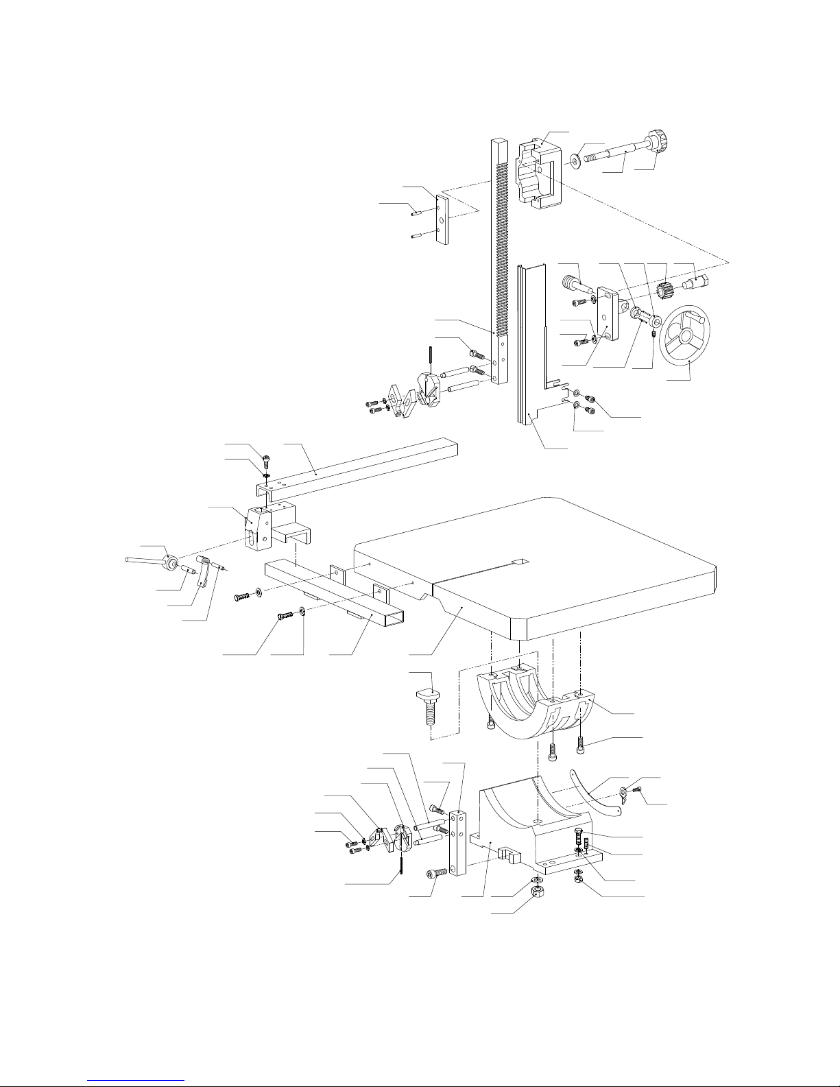
VI THE EXPLODE DRAWING

1
4(4)
7
6(4)
8
13
14
15(6)
16(2)
17
19
20
21
18(4)
5(4)
9(2)
10 12
11(4)
2(2)
3(2)
22
23
24(4)
25(4)
26 27(4)
28(4)
29
30
31(4)
32
33 34(2)
35
36(10)
37(10)
38(2)
39(2)
40
41
54.1(4)
78(4)
79(4)
83
85(2)
84(2)
82(2)
86 87 88 89 90
80
81
91
92
93
94
95
96(2)
42(4)
43(4)
44(4)
45(2)
46(2)
47(2)
45.1(2)
48(2)
49
50 51 52
53
54(8)
55(4)
56(4)
58
57
59
60(4)
61
62
6364
65(2)66(2)
67
68
69
70
71
72(4)
73(4) 74
75(2)
76
77

131.1
116(4)
117(4) 114
115.1(3)
118
119(2)
120(2)
121
122(2)
123(2)
124(2)
125
126(2)
127(2) 128
129
130
131
132
133(4)
134(4)
135
136
137(2)
139
138
140
97(3)
98
99.1(2)
99
100
101(4)
102(4)
103 104(2)
105(2)
106(2)
107
108(2)
110(4)
109
112(2)
113
115
111(2)
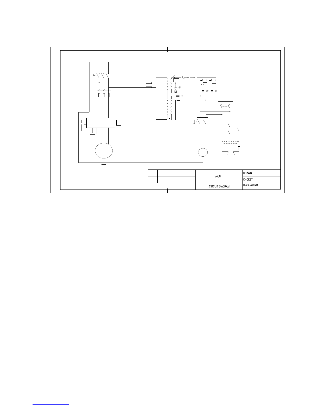
VII THE ELECTRICAL DRAWING FOR VS-400
F U 91 0 A
FU 8 10 A
0 .75 m m
2m m 2
2 .4K V A
35
35
36
SB3
SB 4
45 46
33
34
SQ3
9
SB 1-2
11
22A
5 A
1A
1A
10A10A10A
FU 7
FU 6
FU 5
F U4
FU 3FU 2FU 1
2
0.7 5 m m
2
2m m
L7
U 2 W 2
4 3
42
8
7
65431
0
TC
AC
2 20 V
AC
24V
L8
41
EL2 E L4
EL3
EL1
SB2
SB 1-1
SQ2
SQ1
TA
KM 2
K M 1
KM 1 K M2
S A2
GN D
M2
M1
TS
R
U V W
W
VU
L3 2
L2 2L1 2
L1 1 L2 1 L3 1
PE
14
1 3
CO M
RE V
KM 1
1 01 2
V CI+ 10 V
PE L 3
L2L1
SA 1
4 4
K M 2
Other Bolton Tools Saw manuals


Popular Saw manuals by other brands


Makita
Makita BLS712SF instruction manual

Parkside
Parkside SABRE SAW PFS 710 A1 Operation and safety notes

Clarke
Clarke CONTRACTOR CON850 Operating and maintenance instructions

AEG
AEG US 900 XE Original instructions

U.S.SAWS
U.S.SAWS FSB-150 operating manual

General International
General International 50-760 M1 Setup & operation manual

SawStop
SawStop T-Glide TGP2-FA Installing guide

Kamikaze
Kamikaze KVS8000 user manual

Black & Decker
Black & Decker CS2001 Linea PRO instruction manual

DeWalt
DeWalt DCS375 instruction manual

KAKA Industrial
KAKA Industrial CS-12 Operation manual

Northern Industrial Tools
Northern Industrial Tools 999000 owner's manual