BON ELECTRONICS FM-073SC User manual
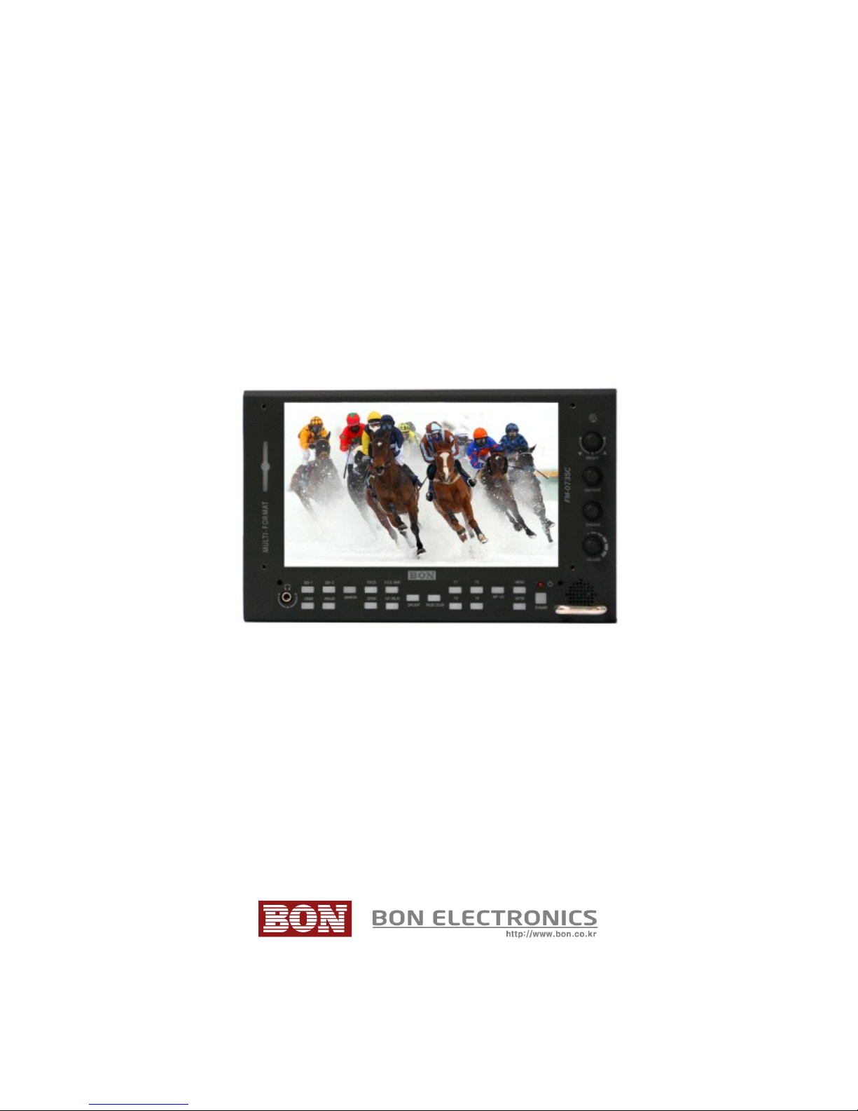
Multi-Format Field Monitor
FM-073SC
User’s Guide

Contents
Features.................................................................................................................3
Safety Instructions................................................................................................4
Front......................................................................................................................5
Rear.......................................................................................................................7
Tally.......................................................................................................................8
Audio Level Meters...............................................................................................8
OS Menu................................................................................................................10
VI EO..................................................................................................................10
ISPLAY 1...........................................................................................................13
ISPLAY 2...........................................................................................................15
COLOR.................................................................................................................17
MARKER..............................................................................................................18
OS 1...................................................................................................................19
OS 2...................................................................................................................21
AU IO..................................................................................................................23
GPI.......................................................................................................................25
SYSTEM..............................................................................................................26
External Remote Control....................................................................................28
List of Compatible Video Formats (H MI/Composite)......................................29
List of Compatible Video Formats (S I)............................................................31
Specifications......................................................................................................33
imensions..........................................................................................................35
Accessories.........................................................................................................36
Troubleshooting..................................................................................................37
Warranty Information..........................................................................................39
Modification of Product.......................................................................................39
Caution on Menu Operation................................................................................39
Caution for Monitor Placement...........................................................................39
2

Features
Auto Flip
Firmware Update with USB Memory
Focus Assistance/False Color
Waveform/Vectorscope
SLR Scales
Closed Caption (CEA-608/708)
Time Code
8~16ch Audio Level Meter
Video Exposure Range Check
IM Mode
AF & V-CHIP(S I Only)
Various Markers
H/V elay
Pixel-to-Pixel View
Tally LE Control Output
R/G/B/W Internal Patterns
Rack & VESA Mount (Option)
Horizontal/Vertical Angle Level Meters
3G S I input (Level A/B)
1~16Ch Audio Level Meters
3

Safety Instructions
•To help avoid damaging your monitor, connect only one power (AC or C) in
operation.
•Rough handling of product may cause physical damage or malfunction.
•Never insert anything metallic into the monitor openings. oing so may create
the danger of electric shock.
•To avoid electric shock, never touch the inside of the monitor. Only a qualified
should open the monitor’s case.
•Openings in the monitor cabinet are provided for ventilation. To prevent
overheating, these openings should not be blocked or covered.
•Put your monitor in a location with low humidity and a minimum of dust. Avoid
places like damp basement or dusty hallways.
•Place the monitor on a solid surface and treat it carefully. The screen is made of
glass and can be damaged if dropped or sharply hit.
•o not attempt to remove the back cover, as you will be exposed to a shock
hazard. The back cover should only be removed by qualified service personnel.
•Unplug the monitor power before you connect external devices to the monitor.
•If your monitor does not operate normally, or if there are any unusual sounds or
smells coning from it, unplug it immediately and contact us.
•Please do not disassemble the monitor. No service will be provided in that case.
•isplaying fixed picture for a long time may cause an afterimage or dead spots.
To recover LC pixels, display whole white picture on screen for a n hour or
two and pixels will be recovered.
•No service will be provided for user’s own color calibration.
4
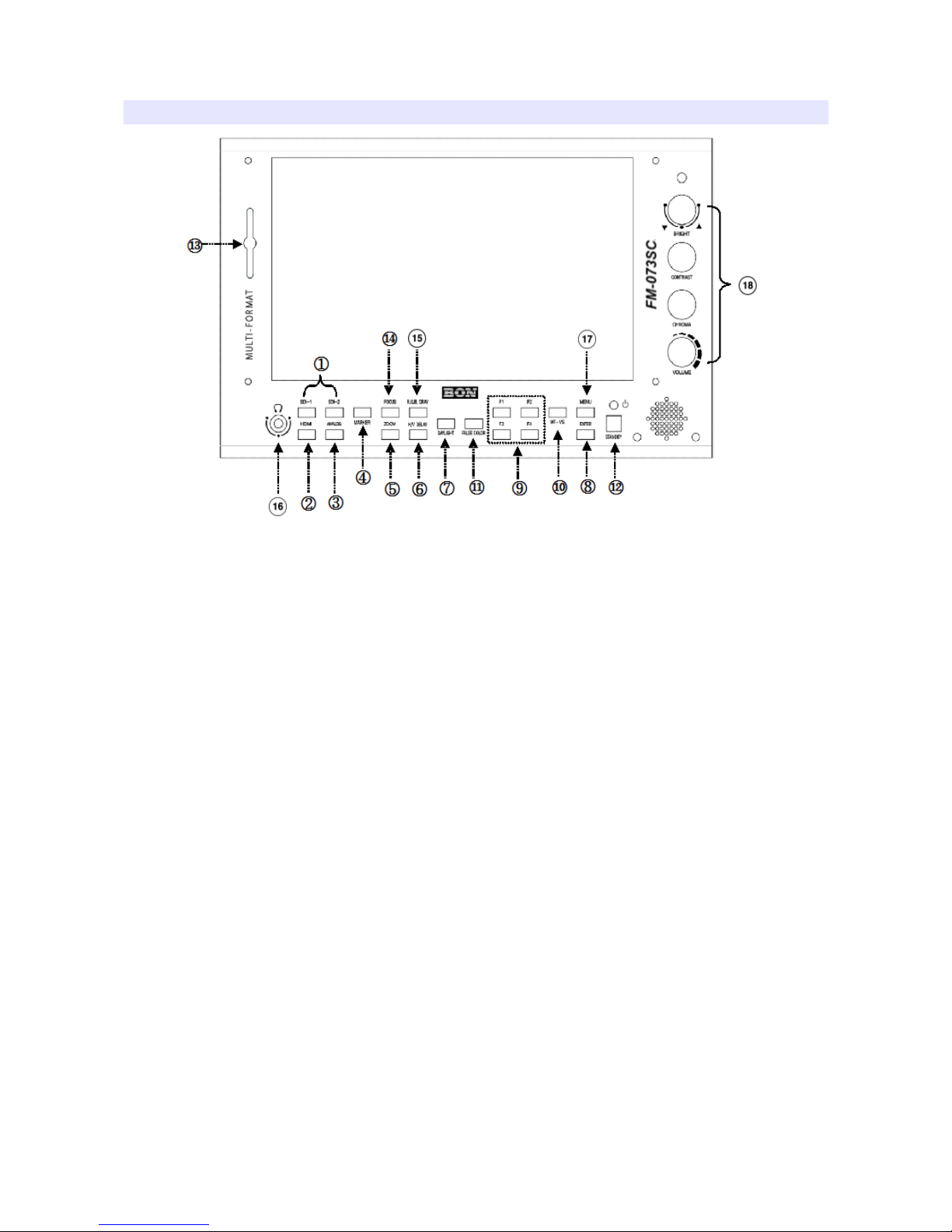
Front
1,2 SDI, HDMI Input Selection
3 Analog Input Selection
Switch input in the order of : YPbPr(Component), CVBS1, CVBS2,
CVBS3(Composites)
4 Marker On/Off
5 Zoom
Switch zoom mode in the order of : Pixel to Pixel, User Zoom, SLR Zoom
Pixel to Pixel
Shows the original picture with 1:1 pixel mapping. If the picture is larger than the
monitor’s LC resolution, the center part of the picture is shown. Use knob to see
a different part of the picture. 5 parts are selectable : CENTER, TOP-LEFT, TOP-
RIGHT, BOTTOM-LEFT, BOTTOM-RIGHT.
User Zoom
This is a custom zoom mode which user can set the zoom level. Turn the knob to
set your own zoom level in this mode.
5

DSLR Zoom
This zoom-in/out preset allows fully scaled-up monitoring of contracted video
from SLRs. Zoom-in/out area can also be customized to allow partial or full view.
To choose camera type, press Menu and choose Video, choose a SLR camera
from Canon 5 Mark II/7 , 60 , Nikon 800, Sony A77, Panasonic GH2 and Canon
5 Mark III.
6 H/V Delay
H/V elay allows you to check the outside signal of active picture area. This mode
is for broadcast professionals. By pressing the button, it switches the mode in the
order of : H elay, V elay, H/V elay, Off.
7 Daylight
This button switches luminance level in the order of :
Normal, Brighter, Brightest
.
Press this button to switch the luminance to see the screen comfortably.
8 Enter
Enter Key.
9 Function Keys
User-preferred function can be assigned to function keys.
10 Waveform / Vectorscope
Waveform enables users to check the luminance level. Vectorscope is for checking
chrominance values of the picture. The mode is switched in the order of :
Waveform, Waveform Parade, Vectorscope, Wide Waveform, Full-Screen
Waveform, Full-Screen Vectorscope.
* Some afterimage might be left on Waveform when the input picture
freezed long on interlace signal.
* On SDI 2K input with sf scanning mode, displaying Circle or
Horizontal Line pattern might cause an afterimage effect. However, it
will be disappeared after the picture is changed.
11 False Color
Shows pictures in specific colors as its luminance level other than the original
colors. Much exposed area is filled with red while little exposed area is purple.
* 10-bit, 12-bit Dithered gradient pattern might not be displayed
clearly in this mode.
6

12 Power Button
Power turns off when pressed for one second.
13 Tally Lamp
Tally lamp displays Red, Green, Amber color tally.
14 Focus Assist
isplays focus area when pressed. The focus sensitivity is adjustable on the
display menu.
15 R/G/B/Gray Only
isplays Red, Green, Blue or Gray only as the button is pressed.
16 Audio Out
Stereo phone jack for audio output.
17 Menu Button
Menu and Exit button.
18 Knobs
Brightness, Contrast, Chroma, Volume adjustable knobs. The brightness knob is
also used as arrow knob to move up and down on the menu, User Zoom, etc.
Rear
7

1 DC Power Jack
7V ~ 24V C power can be used.
2 SDI 1, 2 Input Ports
H S I or S S I input ports. S I signal should be fulfill SMPTE standards.
3 SDI Loop-Through and HDMI-to-SDI Out Port
This port can be used either S I Loop-through or S I out of H MI-to-S I
converter.
4 Component YPbPr or CVBS 1,2,3 Input Ports
Component YPbPr or CVBS(Composite) input ports.
5 Tally Input
To display Red, Green, Amber tally.
6 Update Port (RJ-11 Jack
Serial communication port for updating firmware or monitor control.
7 Control Port
Monitor control port. The detail is in the chapter “Remote Terminal Assignment
Connection”
8 Internal Power Port
External battery power connection port. (7V ~ 24V)
9 USB Port
USB firmware update port.
Tally
Tally mode displays Red, Green, Amber color by the input from tally (RJ-45 GPI)
input port.
Audio Level Meters
Audio level meters displays max 16 channels. But it depends on the number of
channels contained in the signal itself. For example, if the signal contains 2
channels, the audio level should be 2 channels.
The odd channels are displayed in the left, whereas the even channels are in the
right. The position of the meters can be set to top or bottom of the screen on the
8

AU IO section of the menu.
9

OSD Menu
Menu opens up by pressing Menu button. This button also works as Exit button on
the Menu. The brightness knob works as up/down arrow. To select something,
press either enter button or the knob.
* The menu may disappear on no signal or instable signal input.
* Menu setting is saved for each input mode. So the user should make
selection on an appropriate input mode.
VIDEO
Brightness
Adjust brightness. efault: 127.
Contrast
Adjust contrast. efault: 127.
Chroma (Hue
Adjust chroma. efault: 127.
Phase
Adjust phase. efault: 127.
Sharpness
Adjust sharpness. efault: 18.
SDI 3G Mode
Set this mode if the input is 3G H S I. S I 3G mode support SMPTE standards
listed below:
▶A_MS1_YCbCr422_10
10

: 3G SDI Level-A Mapping Structure 1 YCbCr 4:2:2/10 bit
▶A_MS2_YCbCr444_10
: 3G SDI Level-A Mapping Structure 2 YCbCr 4:4:4/10 bit
▶A_MS2_RGB444_10
: 3G SDI Level-A Mapping Structure 2 RGB 4:4:4/10 bit
▶A_MS3_YCbCr444_12
: 3G SDI Level-A Mapping Structure 3 YCbCr 4:4:4/12 bit
▶A_MS3_RGB444_12
: 3G SDI Level-A Mapping Structure 3 RGB 4:4:4/12 bit
▶A_MS4_YCbCr422_12
: 3G SDI Level-A Mapping Structure 4 YCbCr 4:2:2/12 bit
▶B_MS1_YCbCr422_10
: 3G SDI Level-B Mapping Structure 1 YCbCr 4:2:2/10 bit
▶B_MS2_YCbCr444_10
: 3G SDI Level-B Mapping Structure 2 YCbCr 4:4:4/10 bit
▶B_MS2_RGB444_10
: 3G SDI Level-B Mapping Structure 2 RGB 4:4:4/10 bit
▶B_MS3_YCbCr444_12
: 3G SDI Level-B Mapping Structure 3 YCbCr 4:4:4/12 bit
▶B_MS3_RGB444_12
: 3G SDI Level-B Mapping Structure 3 RGB 4:4:4/12 bit
▶B_MS4_YCbCr422_12
: 3G SDI Level-B Mapping Structure 4 YCbCr 4:2:2/12 bit
▶B_2X_DS1_YCbCr422_10
: 3G SDI Level-B Data Stream 1 YCbCr 4:2:2/10 bit, Dual Link SMPTE-372M
▶B_2X_DS2_YCbCr422_10
: 3G SDI Level-B Data Stream 2 YCbCr 4:2:2/10 bit, Dual Link SMPTE-372M
Especially for 3G Level B signals, the format should be set manually.
Also, be aware that the format information might be lost on power down.
SDI Switching
Set this mode for smooth S I switching between two S Is. (e.g. S I 1 to S I 2)
NTSC Setup
Select 0 IRE or 7.5 IRE. 7.5 IRE works on NTSC or S YUV.
11

HDMI UV Swap
Sometimes UV signal might be opposite such input as PC RGB or such resolution
as PC’s. Turn this mode on to see correct color when the incorrect color displayed
on this kind of input.
SDI Output
Sets S I Output to either S I loop-through or H MI-to-S I conversion out.
HDMI Output
Sets H MI Output to either S I loop-through or H MI-to-S I conversion out.
DSLR Camera
Set which SLR camera you use for SLR Zoom mode. SLR Zoom mode can be
set by pressing Zoom button in the front.
12

DISPLAY 1
Aspect
Set the aspect ratio of the screen. 16:9, 4:3, Native(Original) are selectable.
1:1 Scan
Set this on to display picture in 1:1 pixel mapping.
Anarmorphic
Set this mode to resize the screen to 3.56:1, 2.74:1, 2.59:1, 2.55:1, 2.40:1, 2.39:1,
2.35:1, 1.85:1, 1.75:1, 1.66:1, or 1.37:1.
Waveform Display
Select waveform display mode. Choose Normal to analyze whole screen, choose
Line Select to analyze a specific line of the screen.
Waveform Line Select
Select the line when you select Line Select mode for Waveform display.
Waveform Color Mode
Choose either Single or Mixed.
Waveform Intensity
Set waveform color’s intensity between 0~63.
WFM & Vector Size
Set Waveform and Vectorscope size among three kinds.
WFM & Vector Blend
Set transparency of Waveform and Vectorscope window between 0~6.
13

YCbCr
YCbCr is a digital color reproduction standard. Y is for luminance, Cb
is for blue strength, Cr is for red strength.
Timecode Display
Set this mode on to display timecode from S I signal. Select the appropriate
timecode that you wish to display among LTC (Longitudinal Time Code), VITC
(Vertical Interval Time Code), VITC ( igital Vertical Interval Time Code).
Timecode Position
Set Top or Bottom position for timecode.
14
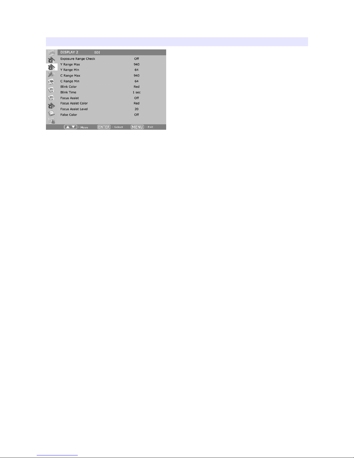
DISPLAY 2
Exposure Range Check (Video Range Check
Checks Y, C level and displays over-exposed or under-exposed area on screen.
The base value can be Y, Cb, or Cr.
Y Range Max / Min
Set Y range value for range check.
C Range Max / Min
Set C range value for range check.
Blink Color
The filled area color by range check can be either Black, Blue, Green or Red.
Blink Time
Set blinking time of the area between 1 to 5 seconds.
Focus Assist
Turns on Focus Assist mode. This mode can be set also by pressing Focus Assist
button in front.
Focus Assist Level (Sensitivity
The sensitivity of the focus assist function can be set between 0 to 48.
Focus Assist Color
Set brush color of focus assist mode among Blue, Green, and Red.
False Color
Shows pictures in specific colors as its luminance level other than the original
15

colors. Much exposed area is filled with red while little exposed area is purple.
* 10-bit, 12-bit Dithered gradient pattern might not be displayed
clearly in this mode.
16
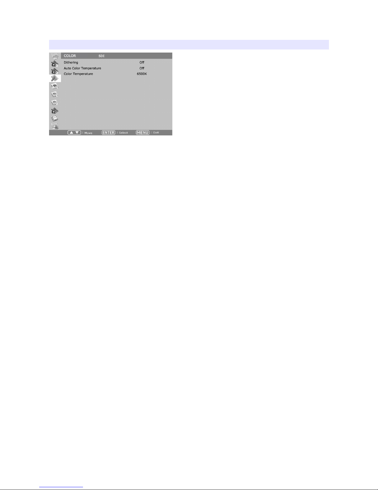
COLOR
Dithering
Set this mode on to display gradient more smoothly.
Auto Color Temperature
Set this mode on to adjust color temperature by temperature change. Its output
might incorrect on some harsh environment.
Color Temperature
VAR, 3200K, 5400K, 6500K, 9300K color temperatures are preset and selectable
by user. On User mode, user can adjust RGB gain and bias. Adjusting on User
mode is recommended to professional users.
17
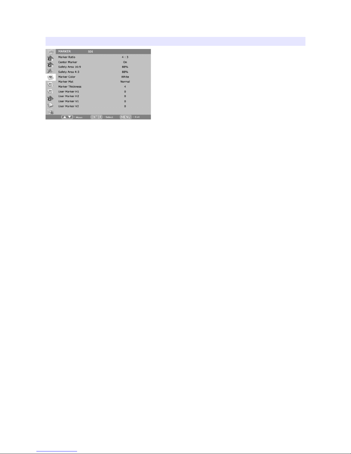
MARKER
Marker Ratio
Select one of preset markers or user marker. To display marker, press Marker
button in front of the monitor.
Center Marker
Set preference to display center marker or not.
Safety Area 16:9
Adjust size of the safety area when marker displayed on 16:9 screen.
Safety Area 4:3
Adjust size of the safety area when marker displayed on 4:3 screen.
Marker Color
Select marker’s color among White, Red, Green, Blue, Gray and Black.
Marker Mat
Set how to display outside of the safety area. Normal, Half(Gray), Black are
selectable.
Marker Thickness
Set marker thickness between 1 to 10.
User Marker H1 / User Marker H2 / User Marker V1 / User Marker V2
Set user marker’s position. H1 for left, H2 for right, V1 for top, V2 for bottom. The
positions are saved as the selected marker name such as USER1.
18

OSD 1
OSD Display Time
Set OS menu display time. Choose 0 for infinite.
OSD Blend
Set transparency of the menu between 0 to 5.
OSD Position
Set menu position among Left Top, Right Top, Left Bottom, Right Bottom and
Center.
V-Chip
S -S I, Composite signal might contain V-Chip data. Turn this mode on to display
V-Chip information on screen.
Closed Caption
Select one of 608 Line 21, 608 VANC, 608 Transcoded, 708 to display Closed
Captions. In special condition such as menu display status, captions are not
displayed.
CC708 Service
Select one of CC service as your preference.
Service 1: general captions.
Service 2: translated captions.
Service 3,4: not assigned.
CC608 StartLine
isplay line of captions are selectable by user. (e.g. 13)
19

Internal Pattern
To test monitor display without signal, turn this mode on. Several patterns such as
Color Bars, Blue, Green, Red, White and Black are selectable.
IMD Display
Set this mode on to display IM text on screen.
IMD Color
Select IM text color among Red, Green, and Amber.
IMD Edit
Set the IM source I to display on screen.
20
Table of contents
Other BON ELECTRONICS Monitor manuals


