Bondline SRM3 Assembly instructions
Instruction Manual Guide
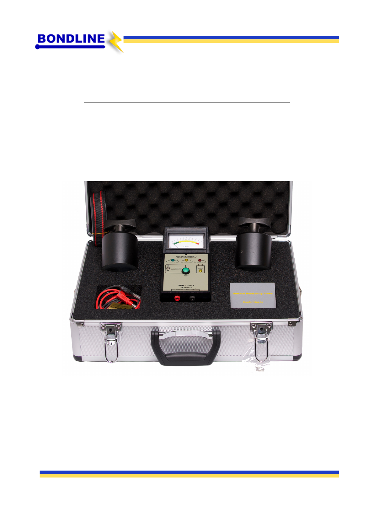
Surface Resistance Test Kit
Bondline Electronics
Unit 4 Rivermead Industrial Estate,
Rivermead Drive, Swindon, Wiltshire,
SN5 7EX
Email: [email protected] Tel: +44(0) 1793 511 000
(SRM3)
www.bondline.co.uk

Instruction Manual Guide - SRM3
Email: [email protected] Tel: +44(0) 1793 511 000
Description
This professional analogue auditors kit can be used for measuring surface resistivity, point-to-point
resistance, point-to-ground resistance and bonding points to ground. The SRM3 kit has been designed
specifically for the purpose of testing surface used in the EPA. Testing and auditing all elements within
the EPA is essential to comply with industry standards. Incorporating the latest requirements of the IEC
613340-5 technical report. Calibration testing is recommended on a regular basis (annually). This
product is CE approved and RoHS and REACH compliant.
Supplied With
2 x 2.5kg weights.
Square probes.
Connecting leads.
9V battery.
Measurement Modes
Both 10v and 100v test voltages are incorporated in the tester with a choice of automatic ranging from
10v – 100v, cleverly detected as you move from Conductive to Dissipative and Insulative surfaces, or
permanent switching to 10v only, an option preferred in very sensitive areas.
Coloured segments and LEDs indicate the following:
Green - Conductive >10^(3) - <10^(6)
Yellow - Dissipative >10^(6) - <10^(11)
Red - Insulative >10^(12)
Operation
1) Check that a good quality Alkaline PP3 battery is fitted - the battery compartment is located at the
rear of the enclosure. If at any time the battery voltage drops below 6.5 volts, the yellow battery low
indicator will light.
2) The aluminum carry case comes with a carrying strap, locking keys and is lined with conductive foam.
3) Connect the RED test lead into the left side RED banana socket, and the BLACK test lead into the right
side BLACK banana socket. To check the meter is functional, press the GREEN test button. The moving
coil needle will move from left to right showing Insulative above 10/13.
4) Connect the two 2.5 kilo (51b) weights to the other end of both the RED and BLACK test leads. Place
the weights gently onto the surface that requires testing and press the test button. The Resistance of
the surface under test will be displayed in Ohms. The GREEN segment of the meter indicates conductive
from > 1.0 x 10/3 to < 1.0 x 10/6. Conductive measurement is taken at a test voltage of 10 volts. The
YELLOW segment indicates dissipative > 1.0 x 10/6 to < 1.0 x 10/12.
Unique analogue meter.
Conductive foam discs.
Carrying case.
www.bondline.co.uk

These measurements are taken automatically at a test voltage of 100 volts, unless the test voltage range
switch is manually switched to 10 volts. 10 volts should only be used for measuring dissipative
resistances, if there is a high risk of damaging components on or around the area under test. At any
other time the meter should be set to 10/100 volts. The RED segment indicates Insulative > 1.0 x 10/12.
For a simple visible check through its range, the meter will indicate Conductive, Dissipative and
Insulative via three LEDs, GREEN = Conductive YELLOW = Dissipative RED = Insulative.
5) The model SRM-3 and the kit includes SP-01 square probe for checking surface resistance in Ohms
per square as used in standard ASTM-D-257, as well as point to point resistance. When using SP-01
square probe, connect the RED and BLACK test leads to their corresponding RED and BLACK sockets.
Place one 2.5 Kilo (51b) weight on the surface of the square probe and press the test button, the
measurement now taken is in Ohms per square.
The SRM3 conforms to the current, IEC61340-5-2:2018, IEC61340-2-3, IEC61340-4-1, ANSI 20.20
standards.
Instruction Manual Guide - SRM3
Calibration
All resistances are in-built using matched fixed resistors. They are measured using an ohm meter which
is of known accuracy and standards used are traceable to UKAS. No variable resistors e.g.
potentiometers are used. The resistances should nevertheless be re-checked once a year. Calibration is
carried out with a Resistance Decade Box.
The resistance decade box required will need a range of either from > 1 kilohm to 999 meg ohms or
10^(9). Measurements greater than 10^(9) are calculated using cad generated techniques, as high
resistances greater than 10^(9).
Connect the test leads from the resistance decade box to the Red and Black banana sockets of the
checker. Set the decade box to the desired resistance i.e. 10^(3) = 1 K, then press and hold the checker's
test button. The 10^(3) LED should light and the analogue meter should read 10^(3), 10 K = 10^(4), the
analogue meter should read this and so on. To measure the changeover point between decades,
increase the resistance of the decade box while pressing the checker's test button. Record the
resistance when the next analogue meter moves up decade permanently (this is the changeover
resistance).
Please note that the checker has no internal parts to adjust, so verification of calibration can be
achieved by using the above process. If verification cannot be achieved the unit should be returned to
the supplier.
The information contained within this instruction manual sheet is for guidance only. We make no warranties expressed or implied and
assume no liability regarding any use of this information.
Table of contents
Popular Test Equipment manuals by other brands

Elcometer
Elcometer 501 operating instructions

RS PRO
RS PRO SLC 1356 instruction manual

Sperry instruments
Sperry instruments STOP SHOCK HGT6120 operating instructions

SMART
SMART KANAAD SBT XTREME 3G Series user manual

Global Specialties
Global Specialties LD-200P user manual

ADTRAN
ADTRAN DS3 NIU MTC Job aid


