MEWOI MEWOI3000+ User guide

- 1-
MEWOI3000+Clamp Earth Tester Field Application Guide
1. Structure of Meter
1).Long Pincers Jaw: 65×32mm
2). HOLD Key: lock / Release display / Storage
3). Trigger: to control opening and closing of jaw
4). ON/OFF Button: Boot Up / Shutdown /*Quit /Clear Data
5). MEM Key: DataAccess / Clear Data
6). Resistance Measure Switch Key Ω (Right Arrow Key)
7).* Current Measure Switch Key A (Left Arrow Key)
8). AL Alarm Function Key: Alarm Open / Turn Off
/ Alarm Critical Value Setting
9). Liquid Crystal Display (LCD)
Note: "*" is limited to D+.
2. Major Technical Specification
Clamp Size
65mm×32mm
Clamp Opening
Extent
32mm
Clamp Dimension
L×W×T: 285mm×85mm×56mm
Weight
1160g(Include batteries)
(han
Range
Range
Resolution
Accuracy
0.010Ω-0.099Ω
0.001Ω
±(1%+0.01Ω)
0.10Ω-0.99Ω
0.01Ω
±(1%+0.01Ω)
1.0Ω-49.9Ω
0.1Ω
±(1%+0.1Ω)
50.0Ω-99.5Ω
0.5Ω
±(1.5%+0.5Ω)
100Ω-199Ω
1Ω
±(2%+1Ω)
200Ω-395Ω
5Ω
±(5%+5Ω)
400-590Ω
10Ω
±(10%+10Ω)
600Ω-880Ω
20Ω
±(20%+20Ω)
900Ω-1200Ω
30Ω
±(25%+30Ω)
Power Supply
6VDC 4 PCS of LR6 alkaline batteries
Shifting
Automatic shifting
Single
measurement time
0.5sec
LCD Screen
4 Digits LCD display, Screen L×W: 47mm×28.5mm
Data memory
99sets
Alarm Sound and
Light
“Beep-beep-beep” alarm tone, Alarm Symbol Flashing, Press AL key to turn on, turn off
Alarm or set Alarm Threshold.
Alarm Threshold
Setting Range
Resistance: 1-1999Ω
Accessories
Meter: 1 piece, Test Ring: 1 Piece, Meter Suitcase: 1 Piece , batteries: 4 PCS ( LR6)

- 2-
3. Principle of Resistance Measurement
The basic principle of MEWOI Clamp earth tester in the measurement of resistance is to
measure the loop resistance, as shown in the figure below. The jaw part of the Meter is
comprised of voltage coil and current coil. The voltage coil provides
excitation signal, and will induce a potential E on the measured loop.
Under the effects of the potential E, the current I can generate on the
measured
loop. The Meter will measure E & I, and
the measured resistance R can be
obtained by the following formula.:
Therefore, The grounding resistance measured by MEWOI3000+ is the sum of the
grounding electrode and the grounding resistance。It can also measure the connection station
of the circuit。
When measuring on the spot, we must pay attention that whether the grounding device is
formed a loop. If it is not a loop, it is necessary to use the auxiliary pole and test wires to
measure its ground resistance.
4. Correct Boot
Press POWER Key to Boot, first, automated testing LCD, show all of its symbols (Figure 1).
Meanwhile the instrument self-calibration, after boot displayed "OL Ω", self-calibration ends and
automatically enter the resistance measurement mode (Figure 2).If not display "OL Ω", press the trigger
to open and close the Jaw for two times and reboot.
Figure 1 Figure 2 Figure 3
Attention:
During the time of self-calibration when you press the POWER button and display
"OL Ω" (self-calibration about one second), the tester cannot clamp around any
metal conductor, cannot turning around the tester, cannot press the trigger and the
jaw of the tester, the tester should be in a naturally closed resting state. Otherwise,
the self-calibration cannot be completed and will have a great impact on the
measurement error.
I
E
R

- 3-
If there is no normal boot self-calibration, instrument will show "Er" symbol, said boot error. need to
check the cause and reboot (Figure 3).
Correct boot, the meter shows "OLΩ", and the user can test it with a random test ring as shown on the
right. The display value should be consistent with the nominal value on the test ring (5.1Ω). It is
normal that there is a little difference between the display value and the nominal value. For example,
when the nominal value of the test ring is 5.1Ω, it is normal to indicate that 5 or 5.2 is normal. Users
can use it safely.
Please refer to the instruction manual for the specific operation of the tester.
5. Application of MEWOI3000+ in various grounding Systems。
Generally, we divide the grounding system into three kinds: Multipoint grounding system, limited
point grounding system and single point grounding system. The following describes the application of
MEWOI3000+ in these three grounding systems
1)Multi-Point Grounding System
Multi-point grounding system (such as electricity transmission tower grounding system,
grounding cable communications systems, certain buildings, etc.) Connect through the ground wire
(cable shielding layer) to form a grounding system. As below, when measuring, the equivalent circuit is
as follows:
Note : R1 is the target grounding resistance.
R0 is the equivalent resistance of the other entire tower grounding resistances paralleled.
Although strictly on the theoretical grounding, because of the existence of so-called "mutual resistance”,
R0 is not the usual parallel value in the sense of electrical engineering (slightly higher than its IEC
parallel output value). But because a tower-grounding hemisphere was much smaller than the distance
between the towers, and with a great number of locations after all, R0 is much smaller than R1.
Therefore, it can be justified to assume R0=0 from an engineering perspective. In this way, the
resistance we measured should be R1.
Times of comparing tests in different environments and different occasions with the traditional method
proved that the above assumption is entirely reasonable.
2) Limited point grounding system
Some tower grounding systems are connected by several towers through overhead ground wires,
and the grounding of some buildings is not an independent grounding network, but several grounding
bodies are connected with each other through wires. This 3 or more than 10 ground system is called a
limited point grounding system.
This situation is common. In this case, if the R0 is taken as 0, the measurement results will have
big error. The resistance can be calculated by a set of nonlinear equations, but it is very difficult to
solve the problem manually. To solve this problem, our company provides a "limited point grounding
system calculation program" software, users can solve the problem through the PC.

- 4-
2)Application of Single-Point Grounding System
According to the measuring principle, MEWOI series Meter can only measure the loop resistance,
and the single-point grounding cannot be measured. However, users will be able to use a testing line
very near to the earth electrode of the grounding system to artificially create a loop for testing. The
following presented two kinds of methods for the single-point grounding measurement by the Meter.
These two methods can be applied to the occasions beyond the reach of the traditional voltage-current
testing methods.
For example, the generator room of the building, the lightning rod, elevator, gas station, ground
cover, and the concrete body cannot be separated from the system grounding and so on, it is very
difficult to test the earth resistance by traditional digital ground resistance tester, but MEWOI3000+ use
auxiliary electrode and a test wire can calculate their grounding resistance.
(a).Two-Point Method
As shown in the figure below, in the vicinity of the measured grounding body RA, find an
independent grounding body of better grounding state RB (for example, near a water pipe or a
building). RAand RBline will connect to each other using a single testing line.
As the resistance value measured by the Meter is the value of the series resistance from the
testing line and two grounding resistances.
RT=RA+ RB + RL
Where: RT is the resistance value measured with the Meter.
RLis the resistance value of the testing line. Meter can measure out the resistance

- 5-
value by connecting the test lines with both ends.
So, if the measurement value of the Meter is smaller than the allowable value of the
grounding resistance, then the two grounding bodies are qualified for grounding resistance.
(b).Three-Point Method
As shown in the figure below, in the vicinity of the measured grounding body RA, find two
independent grounding bodies of better grounding state RB and RC.
First, link RA and RBwith a test line; use the Meter to get the first reading R1.
Second, have RBand RClinked up, as shown in the following figure. Use the Meter to get the
second reading R2.
Third, have RCand RA linked up, as shown in the following figure. Use the Meter to get the third
reading R3.
In the above three steps, the reading measured in each step is the value of the two series
grounding resistance. In this way, we can easily calculate the value of each grounding
resistance:
From: R1=RA+RB R2=RB+RC R3=RD+RA
We get: RA=(R1+R3-R2)÷2
This is the grounding resistance value of the grounding body RA. To facilitate the memory of
the above formula, these three grounding bodies scan be viewed as a triangle; then the
measured resistance is equivalent to the value of the resistance values of the adjacent edges
+ or minus resistance value of the opposite sides, and divided by 2.
As the reference points, the grounding resistance values of the other two grounding bodies
are:
RB=R1-RA RC=R3-RA

- 6-
6. Application of power system
(1) Measurement of grounding resistance of transmission line tower:
Usually the transmission line tower grounding is of multipoint grounding system, clamp the
grounding wire can measure the branch grounding resistance. (See figure below)
Note: if the tester display "L 0.01Ω", means that the tower is with two grounding wires and
underground connecting, in this case, please disconnect the another grounding wire when measuring.
(2) Measurement of neutral grounding resistance of transformer
There are two cases of neutral grounding of transformer: if there is repeated grounding, it will
form multipoint grounding system; if there is no repeated grounding, it can be measured by single point
grounding.
(3)Application of substation in power plant
The tester can measure the contact condition and the connection of the circuit. Through a test
wire, the connection state between the station device and the ground network can be measured.
Grounding resistance can be measured as single point grounding.
7. Application of telecommunication system
(1)Measurement of grounding resistance of the engine room
The computer room of a telecommunications system is often located on the upper floor of a
building and is very difficult to measure with a megger. It is very convenient to test with a MEWOI
Earth Clamp Meter. Connect the fire hydrant and the ground electrode (the fire hydrant is installed in
the engine room)by a wire, and then clamp the wire to measure the earth resistance.
Clamp meter resistance = machine room grounding resistance + test line resistance + fire hydrant
grounding resistance
If the grounding resistance of fire hydrant is very small, then:
Machine room grounding resistance ≈Clamp meter resistance- test line resistance
(2)Measurement of grounding resistance of engine room and transmitting tower
The grounding of the engine room and the transmitting tower is usually made up of two point
grounding system, as follows.

- 7-
If the meter is less than the allowable value of the ground resistance, then the grounding resistance of
the engine room and the transmitting tower is qualified. If the meter measurement is greater than the
allowable value, please measure it by single point grounding
8. Application of building grounding system
If the ground electrodes of each building are independent, see the following ground resistance
measurements for each ground electrode。
If the ground electrodes of the building are connected in the ground, the measured resistance is of
the metal circuit. For ground resistance measurement, refer to the measurement of single point
grounding。
9. MEWOI3000C+ Explosion proof type clamp earth resistance tester application in
grounding system of gas station
Apply to JJF2-2003《Test specification for ground type antistatic device》, The gas station shall
mainly test the grounding resistance and connection resistance of the following facilities。The
instruments used in the test must meet the requirements of GB3836-2000《electrical equipment for
explosive gas atmospheres》
Item
Test Items
Technical requirement
1
Oil tank grounding resistance
≤10Ω
2
Grounding resistance of loading and unloading point
≤10Ω
3
Fuel machine grounding resistance
≤4Ω
4
Connecting resistance of tanker and oil hose
≤5Ω
MEWOI3000C+ has been approved by explosion protection。Its explosion proof sign is ExiaⅡ
BT3 Ga。Explosion proof certificate number:CE13.2263。It can be applied to the corresponding
flammable and explosive environment。The following briefly the application of MEWOI3000C+
explosion-proof earth clamp meter in grounding system of gas station.
(1) Measurement of grounding resistance of oil storage tank and loading and unloading
point:

- 8-
As shown above, in the gas station grounding system, the tank grounding electrode A is connected
with the tanker, and the loading and unloading point grounding electrode C is an independent
grounding electrode. Find another independent grounding electrode as the auxiliary grounding
electrode, B (such as fire hydrant, etc.), according to the three point method, R1, R2 and R3 are
measured with by the tester separately.
It can be calculated:
The grounding resistance of oil storage tank is:RA=(R1+R2-R3)÷2
The grounding resistance of the loading and unloading points is:RC=R2-RA
Auxiliary ground electrode resistance is:RB=R1-RA
Note:When measuring R1, there is no wire connection between BC andAC。Same when test R2、
R3。
(2) Measurement of grounding resistance of tanker:
As shown above, find a ground electrode that is independent of the ground of the tanker, such as
grounding electrode of the point of loading and unloading etc. Connect the two points with the test wire
and measure the resistance RT with the tester. It can be calculated that the grounding resistance of the
tanker is:
R=RT-RC
Among: RT is the resistance measured by the tester。RC is the grounding resistance of the loading and
unloading points。

- 9-
(3)Measurement of connection resistance of oil hose for tanker:
Connect the refueling gun and the tanker by test wire. Check the readings of the tester RT. It can
be calculated:
The connecting resistance of the oiler hose is: R=RT-RL
Among: RT is the resistance measured by the tester。RL is the resistance of the test wire.
10. Selection of measuring points of the tester:
It is important to select the measuring points when testing the grounding resistance. (See figure
below)
At the A point measurement, the meter shows "OL", no loop is formed, and the measuring point is
wrong.
At the B point measurement, the meter shows "L0.01", and the metal loop resistance is measured.
The measuring point is wrong.
At point C, the measurements are correct
11. Other Considerations
Before the start, withhold the trigger one or two times, to ensure that the jaw closed well。
Correct boot,Start measuring after showing“OL Ω”。
The jaw contact surface must be clean, cannot wipe with corrosive and rough material。
The meter is a precision instrument, Be sure to avoid hitting, especially the jaw joint。
When measuring the electric resistance clamp head will be issued consecutive minor "buzz --"
sound, this is normal, pay attention to the difference of "alarm beep, beep, beep, sound。
Don't use this tester for a long time. Please take out the battery。
It is forbidden to use the tester to measure the power line, to measure the high current by
clamp will cause irreversible damage to the magnetic ring of the tester, and even cause the
tester to be scrapped。

- 10 -
12. The difference of earth clamp meter and digital ground resistance tester
Currently in the market there are two kinds of most widely used testers: clamp earth resistance
tester and digital ground resistance tester. The measuring principle of the two instruments is different,
and the requirements of testing are different. Each has its advantages and disadvantages and cannot be
replaced by each other。
Item
Earth resistance clamp meter
Digital earth resistance tester
Measuring Methods
Non-connecting measurement
Connected measurement
Testing Principles
Test Loop Resistance
Pole changing method of rated current
Test condition
The grounding system must form a
loop
Ground pins must be laid in the soil
Suitable for
grounding system
It is especially suitable for multipoint
grounding system
Single point grounding can be aided
by auxiliary pole test
It is especially suitable for single point
grounding system
Release the another electrode for the 2
point above grounding system
Efficiency
Simple and quick operation
Because of the need to install auxiliary
grounding needle, the operation is more
complicated
We always compare the testing results between the earth resistance clamp meter and the digital
earth resistance tester, If the measuring method is correct, the test result will be basically the same. If
the operation is improper, the test result will be different. Please pay attention to the following
considerations:
(1)For digital earth resistance tester measurement, make sure the grounding electrode is released
(that is, the measured grounding and grounding system is disconnected). If not released, the
measured resistance is paralleled value of all the grounding resistance, the paralleled value is
much smaller than the target grounding resistance, and it is no sense. Please refer to GB50061-97
《Code for design of overhead power lines below 60KV》
(2)For digital earth resistance tester measurement, especially the grounding underground trunk is
longer, the probe set whether to meet the following two conditions: the distance between the
probe and the electrode to meet the requirements of the specification, probe and ground or
grounding is vertical layout. Otherwise, the measurement result of the digital meter is inaccurate。
(3)GL/T621-1997《Grounding of AC electrical installations》Regulations:“ The sum of the earth
resistance and the earth wire resistance of the earth electrode or the natural grounding electrode is
called the ground resistance of the grounding device。”
In general, the digital meter can only measure the grounding resistance of the earth electrode, but
cannot measure the resistance of the grounding wire. The earth resistance measured by the earth
resistance clamp meter is the sum of the grounding resistance of the earth electrode and the
grounding wire resistance, and fully meets the requirements of the national standard。
(4)If there are only a few grounding electrodes in the grounding system, there will be some errors in
measuring with a earth resistance clamp meter, which will tend to be larger. To get the accurate
grounding resistance value,《the calculation program of the limited point grounding system》can
be used to solve the problem。

- 11 -
Your Testing Specialist
This manual suits for next models
5
Other MEWOI Test Equipment manuals
Popular Test Equipment manuals by other brands

Ibiza
Ibiza STROBE132LED instruction manual

Hioki
Hioki IM9201 instruction manual

GDD Instrumentation
GDD Instrumentation MPP-EM2S Plus instruction manual
Tektronix
Tektronix TBS1000 Series Safety and installation instructions

Optoelectronics
Optoelectronics Scout user manual
TSI Instruments
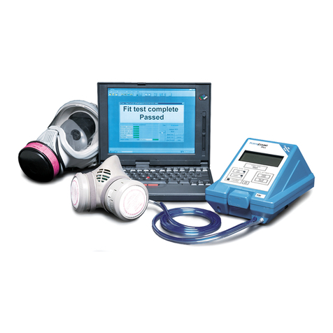
TSI Instruments PortaCount Plus 8020 Operation and service manual

