BONFIGLIOLI Vectron ACTIVE CUBE Series Instructions for use

www.bonfiglioli.com
Bonfiglioli Riduttori S.p.A.
Via Giovanni XXIII, 7/A
40012 Lippo di Calderara di Reno
Bologna, Italy
tel: +39 051 647 3111
fax: +39 051 647 3126
bonfiglioli@bonfiglioli.com
www.bonfiglioli.com
VEC 526 R1
ACTIVE CUBE
Application manual - Positioning
Bonfiglioli has been designing and developing innovative
and reliable power transmission and control solutions
for industry, mobile machinery and renewable energy
applications since 1956.


04/08 Application manual Positioning 1
General Information about the Documentation
This application manual complements the configurations described in the operating
instructions and the „Quick Start Guide“ of the ACU frequency inverters (ACTIVE
Cube series). Configurations 240, 440 and 540, which are described in this applica-
tion manual, contain additional positioning functions.
For better clarity, the documentation is structured according to the customer-specific
requirements made on the frequency inverter.
Quick Start Guide
The Quick Start Guide describes the basic steps required for mechanical and electri-
cal installation of the frequency inverter. The guided commissioning supports you in
the selection of necessary parameters and the software configuration of the fre-
quency inverter.
Operating Instructions
The Operating Instructions describe and document all functions of the frequency
inverter. The parameters required for adapting the frequency inverter to specific
applications as well as the wide range of additional functions are described in detail.
Application Manual
The application manual supplements the documentation for purposeful installation
and commissioning of the frequency inverter. Information on various subjects con-
nected with the use of the frequency inverter are described specific to the applica-
tion.
Installation Instructions
Complementing the Brief Instructions and the Operating Instructions, the Installation
Instructions provide information on how to install and use the additional/optional
components.
If you need a copy of the documentation or additional information, contact your local
representative of BONFIGLIOLI.
The following pictograms and signal words are used in the documentation:
Danger!
Danger refers to an immediate threat. Non-compliance with the precaution described
may result in death, serious injury or material damage.
Warning!
Warning refers to a possible threat. Non-compliance with the warning may result in
death, serious injury or material damage.
Caution!
Caution refers to an immediate hazard. Non-compliance may result in personal or
material damage.
Attention!
Attention and the related text refer to a possible behavior or an undesired condition
which can occur during operation.
Note
marks information which facilitates handling for you and supplements the corre-
sponding part of the documentation.
Application manual Positioning 104/08

2 Application manual Positioning 04/08
TABLE OF CONTENTS
1 General Safety Instructions and Information on Use.................................................. 5
1.1 General Information .............................................................................................. 5
1.2 Purpose of the Frequency Inverters...................................................................... 6
1.3 Transport and Storage........................................................................................... 6
1.4 Handling and Installation ...................................................................................... 6
1.5 Electrical Connection ............................................................................................. 7
1.6 Information on Use................................................................................................ 7
1.7 Maintenance and Service....................................................................................... 7
2System description....................................................................................................... 8
2.1 Terminal diagram ACTIVE Cube (ACU) series........................................................ 9
3 Commissioning of the Frequency Inverter................................................................. 10
3.1 Switching on Mains Voltage ................................................................................ 10
3.2 Commissioning of the motor ............................................................................... 11
3.3 Control Inputs and Outputs................................................................................. 12
3.3.1 Factory settings of the digital inputs ...................................................................... 13
3.4 Digital inputs for speed sensor inputs or for other functions ............................. 15
3.5 Positioning - commissioning procedure .............................................................. 16
3.5.1 Getting started .................................................................................................... 18
3.5.1.1 Motor encoder is position encoder at the same time......................................... 18
3.5.1.2 Two different encoders for motor and positioning ............................................ 19
3.5.1.3 No motor encoder, external encoder for positioning ......................................... 20
3.5.1.4 Consider the operation mode settings for speed sensor input............................ 20
3.5.2 Reference system ................................................................................................ 21
3.5.3 Setting up a motion profile ................................................................................... 24
3.5.4 Control via software............................................................................................. 25
3.5.5 Write index and read index for the motion blocks table ........................................... 26
4 Operation Modes of the Positioning........................................................................... 28
4.1 General Issues about Operation Modes .............................................................. 28
4.1.1 Assignment of digital inputs.................................................................................. 29
4.1.1.1 Instructions on MFI1D (multifunction input)..................................................... 30
4.1.2 Operation modes for controlling the positioning operation ....................................... 31
4.1.3 Input and output signals ...................................................................................... 33
4.2 Homing ................................................................................................................ 34
4.2.1 Automatic of manual start of homing..................................................................... 34
4.2.2 Input and output signals for homing...................................................................... 35
4.2.3 Homing mode......................................................................................................37
4.2.4 Home offset ........................................................................................................38
4.2.5 Speed and acceleration of homing operation .......................................................... 38
4.3 Positioning Mode ................................................................................................. 39
4.3.1 Motion block management.................................................................................... 39
4.3.2 VTable................................................................................................................40
4.4 Positioning Mode And Motion Block Data............................................................ 41
4.4.1 Motion Mode ....................................................................................................... 41
4.4.1.1 Motion mode "absolute"................................................................................. 44
4.4.1.2 Motion mode "relative" ..................................................................................44
4.4.1.3 Motion mode "touch probe" (sensor) .............................................................. 45
4.4.1.4 Motion mode "velocity".................................................................................. 47
4.4.1.5 Combination with electronic gear.................................................................... 48
Application manual Positioning 04/082

04/08 Application manual Positioning 3
4.4.2 Motion block data ................................................................................................ 54
4.4.2.1 Target position.............................................................................................. 54
4.4.2.2 Speed ..........................................................................................................54
4.4.2.3 Acceleration and Deceleration ........................................................................ 55
4.4.2.4 Automatic sequence of motion blocks (next motion block) ................................ 55
4.4.2.5 Single motion................................................................................................62
4.4.3 Control of motion................................................................................................. 63
4.4.3.1 Selection of motion block via digital signals (motion block change-over)............. 63
4.4.3.2 Motion block selection via parameter (starting-record number) ......................... 65
4.4.4 Input and output signals for motion blocks ............................................................ 66
4.4.5 Starting, stopping and resuming ........................................................................... 67
4.4.5.1 Starting and stopping positioning.................................................................... 68
4.4.5.2 Resuming interrupted motion blocks ............................................................... 72
4.4.6 Digital signals for indication of status of motion orders............................................ 73
4.5 JOG Mode............................................................................................................. 76
4.5.1 Fixed speed in JOG mode ..................................................................................... 79
4.5.2 Acceleration and Deceleration in JOG Mode............................................................ 81
4.6 Teach-In (Saving Actual Position as Target Position)......................................... 81
4.7 Electronic gear..................................................................................................... 85
4.7.1 Master position source ......................................................................................... 85
4.7.2 Gear factor..........................................................................................................87
4.7.3 Resynchronization................................................................................................87
4.7.4 Phasing function..................................................................................................87
4.8 Monitoring Functions........................................................................................... 90
4.8.1 Travel limits ........................................................................................................90
4.8.2 Hardware limit switches ....................................................................................... 90
4.8.2.1 Hysteresis for hardware limit switch................................................................ 93
4.8.2.2 Fault reaction................................................................................................94
4.8.2.3 Move away from HW limit switches................................................................. 95
4.8.3 Software limit switches......................................................................................... 95
4.8.3.1 Move away from SW limit switches ................................................................. 98
4.8.4 Target window .................................................................................................... 99
4.8.5 Contouring error supervision............................................................................... 100
4.8.6 Warning mask Application .................................................................................. 102
4.9 Speed Override .................................................................................................. 104
4.10 Position Comparator .......................................................................................... 105
4.11 Rotary Table Application ................................................................................... 107
4.12 Position Controller ............................................................................................. 110
4.13 Store the actual position value (latching function)........................................... 112
4.14 Wiring Example.................................................................................................. 113
5 List of homing modes............................................................................................... 115
5.1 Brief Description Homing .................................................................................. 115
5.2 Overview Table of Homing Types ...................................................................... 117
5.3 Graphic Overview of Homing Modes ................................................................. 118
5.4 Terminology....................................................................................................... 119
5.5 Description of Homing Modes............................................................................ 120
5.5.1 Homing Modes with Ref. Signal........................................................................... 121
5.5.2 Homing modes without reference signal .............................................................. 137
5.5.3 Homing modes, only ref. signal and actual position............................................... 150
6 Output Signals and fault messages.......................................................................... 151
6.1 Actual positioning values................................................................................... 151
Application manual Positioning 304/08

4 Application manual Positioning 04/08
6.2 Status word of the positioning .......................................................................... 152
6.3 Status word 411 ................................................................................................ 154
6.4 Digital Positioning Output Signals..................................................................... 155
6.5 Logic Signal Sources for Positioning ................................................................. 156
6.6 Positioning Error Messages ............................................................................... 158
6.7 Positioning Warning Status ............................................................................... 162
6.8 Diagnosis and fault clearance............................................................................ 162
6.8.1 Touch probe: Drive is decelerated or stops .......................................................... 163
6.8.2 Drive jerks/is very load....................................................................................... 163
7Parameter List.......................................................................................................... 164
7.1 Actual Value Menu (VAL) ................................................................................... 164
7.2 Parameter Menu (PARA).................................................................................... 164
7.3 Parameter list, sorted by function..................................................................... 168
Index .....................................................................................................................................170
Application manual Positioning 04/084

04/08 Application manual Positioning 5
1General Safety Instructions and Information on Use
Warning! The specifications and instructions contained in the documentation
must be complied with strictly during installation and commissioning.
Only qualified staff who has read the documentation and, in particular,
the safety instructions carefully is allowed to carry out installation or
commissioning work or to operate the frequency inverters. The term
„Qualified Staff“ refers to anybody who is familiar with the installation,
assembly, commissioning and operation of the frequency inverter and
has the proper qualification for the job.
The present documentation was prepared with great care and it was subjected to
extensive and repeated reviews. For reasons of clarity, it was not possible to include
all details of all types of the product in the documentation. Neither was it possible to
consider all conceivable installation, operation or maintenance situations. If you re-
quire further information or if you meet with specific problems which are not dealt
with in sufficient detail in the documentation, contact your national BONFIGLIOLI
agent.
We would also like to point out that the contents of this documentation do not form
part of any previous or existing agreement, assurance or legal relationship. Neither
are they intended to supplement or replace such agreements, assurances or legal
relationships. The manufacturer's obligations are exclusively specified in the relevant
purchase contract. This contract also contains all and any warranty regulations which
may apply to the relevant scope of supply. These contractual warranty provisions are
neither extended nor limited by the specifications contained in this documentation.
The manufacturer reserves the right to correct or amend the specifications, product
information and omissions in these operating instructions without notice. The manu-
facturer shall not be liable for any damage, injuries or costs which may be caused by
the aforementioned reasons.
1.1 General Information
Warning! The DC-link circuit of the frequency inverter is charged during opera-
tion, i.e. there is always the risk of contact with high voltage. Frequency
inverters are used for driving moving parts and they may become hot at
the surface during operation.
Any unauthorized removal of the necessary covers, improper use,
wrong installation or operation may result in serious injuries or material
damage.
In order to avoid such injuries or damage, only qualified staff may carry
out the transport, installation, setup or maintenance work required. The
standards EN 50178, IEC 60364 (Cenelec HD 384 or DIN VDE 0100),
IEC 60664-1 (Cenelec HD 625 or VDE 0110-1), BGV A2 (VBG 4) as well
as the applicable national regulations must be complied with. The term
„Qualified Staff“ refers to anybody who is familiar with the installation,
assembly, commissioning and operation of the frequency inverter as
well as the possible hazards and has the proper qualification for the job.
Application manual Positioning 504/08

6 Application manual Positioning 04/08
1.2 Purpose of the Frequency Inverters
Warning! The frequency inverters are electrical drive components intended for
installation in industrial plants or machines. Commissioning and start of
operation is not allowed until it has been verified that the machine
meets the requirements of the EC Machinery Directive 98/37/EEC and
EN 60204. In accordance with the CE marking requirements, the fre-
quency inverters also comply with the Low Voltage Directive 72/23/EEC
as well as EN 50178 / DIN VDE 0160 and EN 61800-2. The user shall be
responsible for making sure that the requirements of the EMC Directive
89/336/EEC are met. Frequency inverters are only available at special-
ized dealers and are exclusively intended for professional use as per EN
61000-3-2.
The frequency inverters are also marked with the UL label according to
UL508c, which proves that they also meet the requirements of the CSA
Standard C22.2-No. 14-95.
The technical data, connection specifications and information on ambi-
ent conditions are indicated on the name plate and in the documenta-
tion and must be complied with in any case. Anyone involved in any
kind of work at the device must have read the instructions carefully and
understood them before starting the work.
Do not connect any capacitive loads.
1.3 Transport and Storage
The frequency inverters must be transported and stored in an appropriate way. Dur-
ing transport and storage the devices must remain in their original packaging. The
units may only be stored in dry rooms which are protected against dust and mois-
ture and are exposed to little temperature deviations only. Observe the climatic con-
ditions according to EN 50178 and the marking on the packaging. The frequency
inverters must not be stored for more than one year without connecting them to
nominal voltage.
1.4 Handling and Installation
Warning! Damaged or destroyed components must not be put into operation
because they may be a health hazard.
The frequency inverters are to be used in accordance with the documentation as
well as the applicable directives and standards. They must be handled carefully and
protected against mechanical stress. Do not bend any components or change the
isolating distances. Do not touch electronic components or contacts. The devices are
equipped with components which are sensitive to electrostatic energy and can easily
be damaged if handled improperly. Any use of damaged or destroyed components
shall be considered as a non-compliance with the applicable standards. Do not re-
move any warning signs from the device.
Application manual Positioning 04/086

04/08 Application manual Positioning 7
1.5 Electrical Connection
Warning! Before any assembly or connection work, discharge the frequency in-
verter. Verify that the frequency inverter is discharged.
Do not touch the terminals because the capacitors may still be charged.
Comply with the information given in the operating instructions and on
the frequency inverter label.
When working at the frequency inverters, comply with the applicable standards BGV
A2 (VBG 4), VDE 0100 and other national directives. Comply with the electrical in-
stallation instructions given in the documentation as well as the relevant directives.
The manufacturer of the industrial machine or plant is responsible for making sure
that the limit values specified in the EMC product standard EN 61800-3 for electrical
variable-speed drives are complied with. The documentation contains information on
EMC-conforming installation. The cables connected to the frequency inverters may
not be subjected to high-voltage insulation tests unless appropriate circuitry meas-
ures are taken before.
1.6 Information on Use
Warning! The frequency inverter may be connected to power supply every 60 s.
This must be considered when operating a mains contactor in jog op-
eration mode. For commissioning or after an emergency stop, a non-
recurrent, direct restart is permissible.
After a failure and restoration of the power supply, the motor may start
unexpectedly if the AutoStart function is activated.
If staff is endangered, a restart of the motor must be prevented by
means of external circuitry.
Before commissioning and the start of the operation, make sure to fix
all covers and check the terminals. Check the additional monitoring and
protective devices according to EN 60204 and applicable the safety
directives (e.g. Working Machines Act, Accident Prevention Directives
etc.).
No connection work may be performed, while the system is in opera-
tion.
1.7 Maintenance and Service
Warning! Unauthorized opening and improper interventions can lead to personal
injury or material damage. Repairs on the frequency inverters may only
be carried out by the manufacturer or persons authorized by the manu-
facturer. Check protective equipment regularly.
Application manual Positioning 704/08

8 Application manual Positioning 04/08
2System description
Positioning via motion blocks enables movement by a certain distance or to a target
position. For each motion block, a separate motion profile can be set, including
speed, acceleration and deceleration ramp. When motion blocks are processed au-
tomatically, the drive will react according to the parameterized behavior when it
reaches the target position.
Scope of functions
−Positioning of linear and round axes
−Optimized round axes positioning (shortest way)
−Absolute and relative positioning
−Touch probe positioning for evaluation of sensors, e.g. motion as from this point
−Specification of values and parameter configuration can be done via user-defined
scale (user units)
−32 motion blocks for different target positions and motion profiles
−Automatic motion block sequence, event or time controlled
−Repetition of motion blocks
−Teach-in function for taking over the actual position value as the target position
in the motion block
−JOG mode for manual operation via digital inputs
−Combination of positioning with electronic gear
−Different homing modes for determining the reference point for positioning
−Control via digital inputs or communication module
−Monitoring: Position monitoring via target window, contouring error monitoring,
hardware and software limit switches
−Parameter configuration via commissioning and diagnosis software VPlus
Components required
Frequency inverter ACU (ACTIVE Cube),
Incremental encoder or resolver,
Suitable extension module,
Interface adapter KP232 for port (A),
Commissioning and diagnosis software VPlus, version 4 or
higher (A)
Optional Components
Communication modules (1 option possible),
Port (B):
CM-232 with RS232 interface,
CM-485 with RS485 interface,
CM-PDP-V1 with Profibus–DP-V1 interface,
CM-CAN with CANopen interface
(B)
Epansion modules (1 option possible), port (C):
EM-ENC for detailed evaluation of incremental encoder (TTL
to RS-422A/RS-485 or HTL, DC 5 to 30 V),
EM-IO for additional analog and digital outputs; depending on
module, system bus interface available, too,
EM-RES for resolver evaluation; depending on module, sys-
tem bus interface available, too,
EM-SYS for communication via system bus
(C)
(A)
(B)
(C)
Application manual Positioning 04/088

04/08 Application manual Positioning 9
2.1 Terminal diagram ACTIVE Cube (ACU) series
The terminal diagram shows an example of a linear axis, with standard parameter
configuration of digital inputs. The sensor is evaluated using an EM extension mod-
ule.
ACTIVE Cube
RS232
X2
UVW
X410A
EM
X410B
VPlus
1234567
X210A X210B
+20V
GND
S1IND
S2IND
S3IND
S4IND
S5IND
S6IND
S7IND
S1OUTD
MFO1A
10VRef
MFI1D
GND
1234567
STOA
S2 SMFI1DS3
S4S6S5
STOB
Terminal diagram ACTIVE Cube (ACU) series
: clockwise; : Anticlockwise
Switch Function
STOA Wire input S1IND as shut-down path STOA of safety function STO 1)
STOB Wire input S1IND as shut-down path STOB of safety function STO 1)
S2 Start positioning or clockwise operation in JOG mode
S3 Stop positioning or anticlockwise operation in JOG mode
S4 Limit switch for limitation of motion range in positive direction 2)
S5 Limit switch for limitation of motion range in negative direction 2)
S6 Home switch for homing, point of reference for absolute positioning
SMFI1D Change-over between positioning mode and JOG mode (JOG mode in
manual mode)
1) Safety function STO (Safe Torque Off) is wired through two channels via inputs STOA and
STOB. This safety function is described in user manual "Safe Torque Off". The "Safe Torque
Off" user manual must be complied with when using the "Safe Torque Off" function.
2) Different from the factory setting. Assign S4IND and S5IND to the parameters for HW limit
switches. Set Parameter Operation mode 490 of speed sensor 1 to „0 - Off“.
Application manual Positioning 904/08

10 Application manual Positioning 04/08
3Commissioning of the Frequency Inverter
Warning! Carry out the electrical and mechanical installation according to the
operating instructions or the "Quick Start Guide" of the frequency in-
verter. Comply with the safety instructions provided there.
Frequency inverters of the ACU series feature the "Safe Torque Off"
function. In any case comply with the application manual "Safe Torque
Off" when using this safety function.
3.1 Switching on Mains Voltage
After completion of the installation work, make sure to check all control and power
connections again before switching on the mains voltage. If all electrical connections
are correct, make sure that the frequency inverter is not enabled. After power-up,
the frequency inverter carries out a self-test and the relay output (X10) reports
"Fault".
Switch off release of frequency inverter:
Control inputs S1IND (STOA) and S7IND (STOB) open
After a few seconds, the self-test is complete, the relay (X10) picks up and signals
"no fault ".
If the unit is in "as-delivered" condition or after resetting the unit to the factory set-
tings, the guided commissioning procedure is started automatically. On the control
unit, the “SetUP“ menu from the menu branch CTRL is displayed.
Application manual Positioning 04/0810
04/08 Application manual Positioning 11
3.2 Commissioning of the motor
Caution!
During the guided commissioning, comply with the safety instructions in
chapter "General Safety Instructions and Information on Use" and in
the Operating Instructions or the "Quick Start Guide" of the frequency
inverter.
Carry out the guided commissioning procedure of the frequency inverter for one of
the configurations listed below. These configurations contain the motion block posi-
tioning functions.
Note:
The guided commissioning contains the function for parameter identifi-
cation. The parameters are determined by way of measurement and set
accordingly. In the case of higher requirements as regards the accuracy
of the speed/torque control, you should carry out the guided commis-
sioning procedure once again under operating conditions because
part of the machine data depends on the operating temperature.
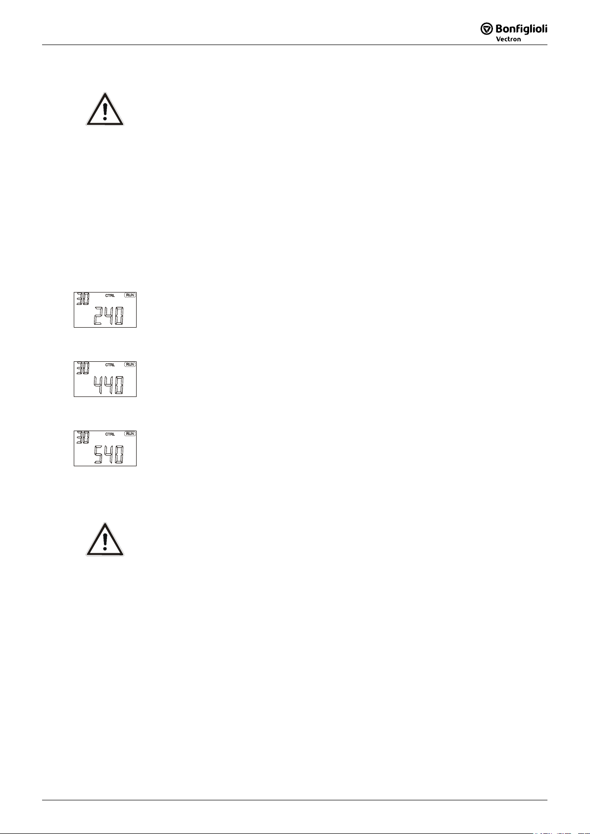
Configuration 240, field-orientated control with positioning
Configuration 240 extends the field-oriented control of an asynchronous machine by
the positioning functions.
The motor controller and the position controller can use the same encoder (motor
encoder) or different encoders (motor encoder and position encoder).
Configuration 440, sensorless field-orientated control with positioning
Configuration 440 extends the sensorless field-oriented control of an asynchronous
machine by the positioning functions.
The motor is controlled without sensors. The positioning controller can be used via
any encoder input.
Configuration 540, field-orientated control of synchronous machine with
positioning
Configuration 540 extends the field-oriented control of a synchronous machine by
the positioning functions. Extension module EM-RES with resolver interface are re-
quired for this.
The motor controller and the position controller can use the same encoder (motor
encoder) or different encoders (motor encoder and position encoder).
Caution!
To enable control of a synchronous machine in configuration 540, pa-
rameter Offset 382 must be set before the guided commissioning. To
do this, proceed according to the operating instructions for the exten-
sion module EM-RES installed. Otherwise, personal or machine damage
may occur.
Note:
For first commissioning, the drive can be controlled manually, using the
JOG function, via the "FUN" key or the digital inputs.
The processing speed of automatic motion block sequence can be re-
duced for commissioning. To do this, use the speed override function.
Note:
The motor encoder should only be used for motor and position control
in slip-free systems (e.g. linear spindle). In systems where slip may
occur (e.g. wheel/rail systems) always use a position encoder to obtain
optimum results.
Application manual Positioning 1104/08

12 Application manual Positioning 04/08
3.3 Control Inputs and Outputs
The modular structure of the frequency inverters enables a wide spectrum of appli-
cations on the basis of the available hardware and software functionality. The func-
tionality of the control inputs and outputs described in the "Quick Start Guide" and
operating instructions is extended in the described configurations.
Caution!
Switch off power supply before connecting or disconnecting the control
inputs and outputs. Verify that the keyed control inputs and outputs are
deenergized before connecting or disconnecting them. Otherwise, com-
ponents may be damaged.
The unit may only be connected with the power supply switched off.
Make sure that the frequency inverter is discharged.
ACU frequency inverters of ACTIVE Cube series
Control terminal X210A
X210A.1 +20 V voltage output (Imax=180 mA) or
input for external power supply 24 V
X210A.2 GND 20 V/ GND 24 V (ext.)
X210A.3 Safety function, digital input STOA
X210A.4 −Start Positioning
−JOG Clockwise
−Store actual position value (latching)
X210A.5 −Stop Positioning
−JOG Anticlockwise
−Touch probe
X210A.6 Encoder 1 Track B 1) or
freely programmable 2)
X210A.7 Encoder 1 Track A 1) or
freely programmable 2)
Control terminal X210B
X210B.1 Home switch 3) or
Encoder 1 Zero Track Z 4)
X210B.2 Safety function, digital input STOB
X210B.3 Operating message
X210B.4 Analog signal of actual frequency
X210B.5 Supply voltage +10V
X210B.6 −Change-over position control/JOG
mode (JOG mode active)
−Teach-In-Signal
S7IND
S1OUT
MFO1A
+10 V/4 mA
MFI1D
GND 10 V
1
2
3
4
5
6
7
X21
0
A
+20 V / +24 V ext.
GND 20 V / GND 24 V ex
t
STOA
STOB
S1IND
S2IND
S3IND
S4IND
S5IND
S6IND
X210B
1
2
3
4
5
6
7
+B
-
A
Z
X210B.7 Ground 10 V
1) Factory setting in configuration 240
2) If no speed sensor is connected to S4IND/S5IND the digital inputs can be used freely program-
mable (e.g. for hardware limit switches).
3) Factory setting in configurations 240, 440 and 540
4) For evaluation of an encoder zero track an Operation Mode 490 for speed sensor 1 higher than
1000 must be selected. Linking of other functions to this input are not active.
The connection diagram describes the default assignment of control terminals and
functions in the different configurations positioning control. According to the re-
quirements of the application, the other functions can be assigned to the control
terminals.
Note:
In order to fully use the positioning functions, an optional extension
module is required. This module enables, for example, encoder evalua-
tion, motion-block change-over or reference percentage change-over.
Application manual Positioning 04/0812

04/08 Application manual Positioning 13
3.3.1 Factory settings of the digital inputs
Control input functions
Digital
Input
Control
terminal
Control positioning JOG mode /
Teach-in
Digital inputs of frequency inverter:
S1IND X210A.3 Digital input STOA for safety function
S2IND X210A.4 Start
Positioning
Store actual
position value 3)
JOG Clockwise
S3IND X210A.5 Stop Positioning,
Touch probe 1)
JOG Anticlockwise
S4IND X210A.6 Freely programmable or
Encoder 1 Track B
2)
S5IND X210A.7 Freely programmable or
Encoder 1 Track A
2)
S6IND X210B.1 Home switch or
Encoder 1 Zero Track Z
2)
X210B.2 Digital input STOB for safety function
MFI1D X210B.6 Change-over position con-
trol/JOG mode (JOG mode ac-
tive)
Teach-in signal in teach-
in mode
Digital inputs extension module:
EM-S1IND Motion Block Change-Over 1
Alternative: - Encoder 2 Zero Track Z
- Fixed frequency change-over 1
- Fixed percentage value change-over 1
EM-S2IND Motion Block Change-Over 2
Alternative: - Encoder 2 Track A
- Fixed frequency change-over 2
- Fixed percentage value change-over 2
EM-S3IND
depending
on module
Motion Block Change-Over 3
Alternative: - Encoder 2 Track B
1) Comply with the notes in section 4.4.1.3.
2) Dependent on the settings of parameters Configuration 30 and Operation
Mode 490. See chapter 3.5.1.4.
3) Switch on the function via parameter Operation Mode 1280. Comply with the
notes in section 4.13.
Control terminal/ Description
Identification
X210A.4
Start Positioning
The input is assigned to parameter Start Positioning 1222.
When activated, the Starting-Record Number 1228 or another
motion block selected by the motion block change-over function
is started.
The motion blocks can be switched via digital inputs EM-S1IND,
EM-S2IND and EM-S3IND of an extension module.
JOG Clockwise In JOG mode, the drive is moved in positive direction (clockwise)
at an adjustable fixed speed. JOG mode is activated via terminal
X210B.6. In teach-in operation modes (Operation Mode 1221),
the JOG function is activated automatically.
Store actual position
value
The function can be switched on via parameter Operation Mode
1280. With signal edge the actual position value is stored in the
EEPROM and displayed via Latched Position 1281.
Application manual Positioning 1304/08

14 Application manual Positioning 04/08
X210A.5
Stop Positioning The drive stops at the current position at deceleration ramp set in
Deceleration 1206.
JOG Anticlockwise In JOG mode, the drive is moved in negative direction (anti-
clockwise) at an adjustable fixed speed. JOG mode is activated
via terminal X210B.6. In teach-in operation modes (Operation
Mode 1221), the JOG function is activated automatically.
Touch probe Input for momentary contact switch or sensor for setting the
reference position. Effective in Motion Mode 1208 with touch-
probe. Rising or falling edge (depending on setting of Motion
Mode 1208) on input sets the point of reference at the current
position. As soon as the signal is received, the drive moves by
the relative distance of parameter Target Position/Distance
1202. Parameter configuration for digital signal "Stop Position-
ing" should be changed when touch probe mode is used.
X210A.6
Encoder 1 Input Encoder 1 Track B, HTL, DC 12 … 30 V
or freely programma-
ble
Evaluation of parameterized functions if the terminal is not used
as encoder input.
Possible function:
Pos. HW Limit Switch
Input for positive hardware limit switch. Limitation of travel range
in positive direction. The drive reacts according to parameter
Fault Reaction 1143 when the switch is reached. Positive direc-
tion (clockwise direction) is disabled.
Set parameter Pos. HW Limit Switch 1138 = “540 - S4IND in-
verted (Hardware)“. Set Parameter Operation Mode 490 of
speed sensor 1 = “0 - Off”. If X210A.6 is used as encoder input
the HW limit switch function is not evaluated as this input.
X210A.7
Encoder 1 Input Encoder 1 Track A, HTL, DC 12 … 30 V
or freely programma-
ble
Evaluation of parameterized functions if the terminal is not used
as encoder input.
Possible function:
Neg. HW Limit Switch
Input for negative hardware limit switch. Limitation of travel
range in negative direction. The drive reacts according to pa-
rameter Fault Reaction 1143 when the switch is reached. Nega-
tive direction (anticlockwise direction) is disabled.
Set parameter Neg. HW Limit Switch 1137 = “541 - S5IND in-
verted (Hardware)“. Set Parameter Operation Mode 490 of
speed sensor 1 = “0 - Off”. If X210A.7 is used as encoder input
the HW limit switch function is not evaluated as this input.
X210B.1
Home switch Input for reference cams. Marks the point of reference for abso-
lute positioning. Via parameter Home Switch 1139, the logic
status of the switch is evaluated.
or Encoder 1 Input Encoder 1 Zero Track Z, HTL, DC 12 … 30 V.
Select one of the settings 1001 … 1132 (with reference pulse) for
parameter Operation Mode 490.
Application manual Positioning 04/0814

04/08 Application manual Positioning 15
X210B.6
JOG-Mode Active Activates JOG mode. JOG clockwise via terminal X210A.4 or JOG
anticlockwise via terminal X210A.5 is executed.
In teach-in operation modes (Operation Mode 1221), the JOG
function is activated automatically.
Teach-In When a rising signal edge is received, the current position in the
selected motion block is saved as the target position.
The motion block is selected by parameter Starting-Record Num-
ber 1228 or the motion block change-over function (parameters
1224 to 1227 and 1254).
The function is activated via Operation Mode 1221.
Parameter Teach-In-Signal 1239 must be assigned the digital
input signal or the logic signal which is to trigger saving of the
actual position.
3.4 Digital inputs for speed sensor inputs or for other functions
The setting of parameter Operation Mode 490 of speed sensor 1 affects the processing of
functions which are linked to the digital inputs S4IND, S5IND and S6IND:
−In the settings 1 … 132 for Operation Mode 490 the digital inputs S4IND and S5IND are
prepared for speed sensor inputs.
−In the settings 1001 … 1132 for Operation Mode 490 the digital inputs S4IND, S5IND and
S6IND are prepared for speed sensor inputs.
The setting of the digital inputs as speed sensor inputs (1 … 1132 for Operation Mode 490)
has higher priority than the control of other functions via these inputs. Other functions will not
be evaluated.
Set Operation Mode 490 to “0 - Off” if S4IND, S5IND and S6IND shall not be used as speed
sensor inputs but for control of other functions via these inputs.
Selection for
Operation Mode 490
S4IND, S5IND and S6IND as
speed sensor inputs or for other functions
0
Functions which are assigned to the digital inputs S4IND, S5IND and
S6IND will be evaluated. The digital inputs S4IND, S5IND and S6IND
are not prepared as speed sensor inputs.
1 … 132 The digital inputs S4IND and S5IND are prepared as speed sensor in-
puts. Other functions which are assigned to the inputs S4IND and
S5IND will not be evaluated.
1001 … 1132 The digital inputs S4IND, S5IND and S6IND are prepared as speed sen-
sor inputs. Other functions which are assigned to the inputs S4IND,
S5IND and S6IND will not be evaluated.
For the settings of speed sensor inputs also refer to section 3.5.1.
Application manual Positioning 1504/08

16 Application manual Positioning 04/08
3.5 Positioning - commissioning procedure
Terminal assignment:
S1IND (STOA) and S7IND (STOB): LOW signal
S2IND (Start positioning): LOW signal
S3IND (Stop positioning): LOW signal
S4IND and S5IND: encoder track B and track A or for parameterized function
S6IND: home switch or encoder zero track Z
MFI1D (JOG mode): LOW signal
Commissioning of frequency inverter:
Comply with chapter "Commissioning of Frequency Inverter",
set up configuration 240, 440 or 540,
switch on power supply,
start commissioning and diagnosis program VPlus (if not yet done for commission-
ing),
Set up reference system (motion distance per rotation of drive and gear factor),
Select suitable homing mode,
Select encoder source for positioning
For manual mode (JOG mode):
Set up parameters for JOG mode or use factory settings,
Release with HIGH signal on S1IND (STOA) and S7IND (STOB),
Activate JOG mode with HIGH signal at MFI1D, clockwise via S2IND, anticlockwise
via S3IND, perform function test
Entering motion profile:
In VPlus, set up the parameters of the motion blocks,
switch on speed override, in order to position at reduced speed during commission-
ing.
Start positioning:
Check readiness for operation: when green LED is flashing: ready for operation; if
green and red LED are flashing: ready for operation and warning message is pre-
sent, repair fault,
Release with HIGH signal on S1IND (STOA) and S7IND (STOB) and start of position-
ing with HIGH signal on S2IND
For communication via field bus or system bus: Set up other parameters according
to operating instructions of the corresponding extension or communication module.
Motion blocks
The motion profile is defined in motion blocks, indicating the target position, speed
and acceleration. A positioning operation may comprise a maximum of 32 motion
blocks.
Discrete selection: Each of the 32 motion blocks can be selected both via logic sig-
nals and parameters (also for transfer via field bus or system bus).
Cycle: The motion blocks can be repeated or processed in a freely programmable
order.
In the motion blocks, the motion block to be processed next can be identified.
The next motion block can be activated:
- by events, e.g. via digital inputs or logic signals
- after a definable delay
In the motion block, the motion mode is selected: absolute (referred to a fixed ref-
erence position), relative (to moving distance, referred to last position approached)
or "Touch Probe" (to moving distance, referred to a sensor signal on digital input
S3IND).
Application manual Positioning 04/0816

04/08 Application manual Positioning 17
Digital signals for status indication
Digital signals can be influenced depending on the status of a motion order. For
example, a digital signal can be parameterized such that it signals reaching of the
target position or the end of the motion block.
JOG mode
The drive is operated manually via two digital inputs at a parameterizable, fixed
speed. This enables for example functional tests for commissioning and approaching
of positions for teach-in mode.
Teach-In
With this function, any position approached can be entered directly in a motion
block as a target position. The required position can be approached in JOG mode.
The current position value is saved as the target position when an increasing edge
is present on the teach-in terminal.
Homing
To determine the drive speed and position, the frequency inverter captures the sig-
nals from position sensors such as incremental encoders or resolvers. When the
frequency inverter is switched on, there is no relation between the position sensor
and the mechanical position of the axis. In order to determine an absolute point of
reference (reference position) for the positioning operation, a homing operation
must be performed. All absolute position data is referred to this reference position.
By selecting a certain homing mode, you can define in which direction the reference
position is to be found and which type of switch (limit switch, home switch) is used.
In the homing operation, the drive moves to the reference position and stops there.
Monitoring
To limit the motion range and protect the machine, limit switches are connected to
the digital input terminals of the frequency inverter. The behavior of the drive when
reaching the limit switches is parameterizable (e.g. error switch-off, shut down).
Software limit switches enable monitoring of the permissible motion range. Position-
ing commands will be executed only within the range defined by parameters. The
software limit switches are active only after a successful homing operation.
The adjustable target window monitors the current position after performance of a
positioning operation. Reaching of the required position is signaled only if the cur-
rent position is within the target window.
The contouring error monitoring function monitors the maximum permissible devia-
tion of the current position and the required position. This monitoring function de-
termines how accurately the positioning operation must be performed.
Application manual Positioning 1704/08

18 Application manual Positioning 04/08
3.5.1 Getting started
In order to use the positioning function, you must start the frequency inverter in
Configuration 240, 440 or 540. If required, perform a motor measurement. Several
functions will be readjusted as soon as you set up the configuration of the position-
ing operation. This includes the functions of the digital inputs.
Warning! Ensure that your parameterization corresponds to the connected termi-
nals.
For commissioning, you must select different configurations for the following cases:
Case Description Possible Configuration 30
1 Motor encoder is position encoder at the
same time
240, 540
2 Two different encoders for motor and
positioning
240, 540
3 No motor encoder, external encoder for
positioning
440
3.5.1.1 Motor encoder is position encoder at the same time
In slip-free systems, the motor encoder can be used as position encoder at the same
time. By using one encoder for both functions, the overall costs can be reduced.
Configuration 30 = 240 | 540, motor encoder = position encoder
Encoder 1 Encoder 2 Motor controller
Operation Mode
490
Operation Mode
493
Actual Speed Source 766
Division Marks
491
Division Marks
494
Actual Position Source 1141 =
“0 - As P. 766 Actual Speed Source”
Level 495
In the corresponding parameters, set up the properties of the encoders according to
the wiring of Encoder 1 or Encoder 2. The parameters of Encoder 2 are available
only if the corresponding extension module is connected.
Adjust parameter Actual Speed Source 766 to connected encoder.
Adjust parameter Actual Position Source 1141 to "0 - As P. 766 Actual Speed
Source" (corresponds to factory settings).
Application manual Positioning 04/0818
Other manuals for ACTIVE CUBE Series
1
Table of contents
Other BONFIGLIOLI Vectron Inverter manuals

Popular Inverter manuals by other brands

YASKAWA
YASKAWA VS MINI J7 instruction manual

Energizer
Energizer EN150 owner's guide

3B SCIENTIFIC PHYSICS
3B SCIENTIFIC PHYSICS U56001 instruction sheet

Western
Western Leonardo Off-Grid 4kW-5000-48 MG user manual

Velleman
Velleman PI600M user manual

Xantrex
Xantrex XPower Powerpack 400 Plus, 400 R owner's guide

Hoymiles
Hoymiles HM-800T Quick installation guide

Moso
Moso SF1.6KTL-S manual

Siemens
Siemens MICROMASTER Vector Series operating instructions

Siemens
Siemens MICROMASTER 420 Getting started guide

Generac Power Systems
Generac Power Systems 6055 owner's manual

ZUCCHETTI
ZUCCHETTI 3PH 10KTL-15KTL-V2 user manual


