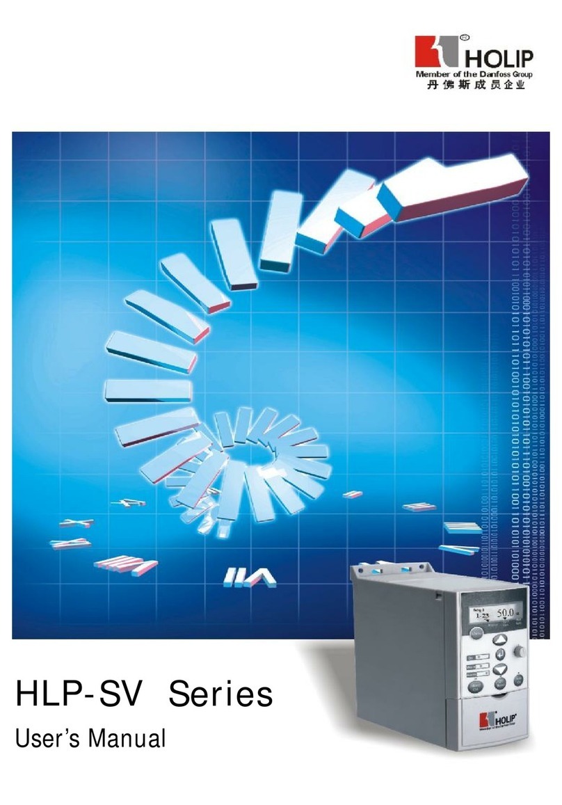
Holip HLP-A Series User manual


HLP-A Series


HLP-A Series
HLP-A Series
I. Introduction 1
1. Checks upon Delivery 2
2. Nameplate Description of HLP Series Inverter 3
II. Safety Precautions 4
1. Before the Power-up 4
2. During the Power-up 6
3. During the Operation 6
III. Standards and Specications 7
1. Particular Specications 7
2. General Specications 9
IV. Storage and Installation 11
1. Storage 11
2. Installation Site and Environment 11
3. Installation and Direction 11
V. Wiring 13
1. Main Circuit Wiring Schematic Diagram 13
2. Description of Terminal Block 14
3. Basic Connection Diagram 16
4. Precautions on Wiring 19
VI.Instruction of the Digital Operator 23
1. Description of the Digital Operator 23
2.Description of the panel type 24
3.List of the panel used in inverter 24
4.Description of Indicator Lamp Status 24
5. Description of Operation Examples 25
VII. Commissioning 27
1. Important Checks before the Commissioning 27
2. Commissioning Methods 27
VIII. Function List 28
IX. Descriptions of Functions 35

HLP-A Series
HLP-A Series
X. Care & Maintenance, Fault Information and Troubleshooting 82
1. Precautions about Inspection and Maintenance 82
2. Periodical Inspection and Maintenance items 82
3. Fault Indication and Troubleshooting 82
4. Faults and Analysis 86
XI. Selection of Peripheral Devices and Disposition 88
1. Options 88
2. Disposition 89
XII. Appendices 93
Appendix 1: Simple Examples of Application 93
Appendix 2: Appearance and Installation Dimensions 100
Appendix 3: Appearance and Installation Dimensions 105
Appendix 4: Description of Parameter Setting for HLP-A Inverter 106
Appendix 5: User’s Records and Feedback 108

HLP-A Series
HLP-A Series - 1-
I. Introduction
Thank you for purchasing and using the general-purpose inverter of HLP
series of multi-functions and high performance.
Please read carefully the operation manual before putting the inverter to
use so as to correctly install and operate the inverter, give full play to its
functions and ensure the safety. Please keep the operation manual handy
for future reference, maintenance, inspection and repair.
Due to the inverter of a kind of electrical and electronic product it
must be installed, tested and adjusted with parameters by specialized
engineering persons of motors.
The marks of Danger Caution and other symbols in the manual
remind you of the safety and prevention cautions during the handling,
installation, running and inspection. Please follow these instructions to
make sure the safe use of the inverter. In case of any doubt please contact
our local agent for consultation. Our professional persons are willing and
ready to serve you.
The manual is subject to change without notice.
Danger indicates wrong use may kill or injure people.
Caution indicates wrong use may damage the inverter or
mechanical system.
Danger
● Be sure to turn off the input power supply before wiring.
● Do not touch any internal electrical circuit or component when the
charging lamp is still on after the AC power supply is disconnected,
which means the inverter still has high voltage inside and it is very
dangerous.
● Do not check components and signals on the circuit boards during
the operation.
● Do not dissemble or modify any internal connecting cord, wiring or
component of the inverter by yourself.
● Be sure to make correct ground connection of the earth terminal of
the inverter.
● Never remodel it or exchange control boards and components by
yourself. It may expose you to an electrical shock or explosion, etc.

HLP-A Series
HLP-A Series
- 2-
1. Checks upon Delivery
The inverter has been strictly and well packed before ex-work. In
consideration of various factors during the transportation special
attention should be paid to the following points before the assembly and
installation. If there is anything abnormal please notify the dealer or the
relevant people of our company.
● Check if the inverter has got any damage or deformation during the
transportation and handling.
● Check if there is one piece of HLPseries inverter and one copy of the
instruction manual available when unpacking it.
● Check the information on the nameplate to see if the specications
meet your order (Operating voltage and KVA value).
● Check if there is something wrong with the inner parts, wiring and
circuit board.
● Check if each terminal is tightly locked and if there is any foreign
article inside the inverter.
● Check if the operator buttons are all right.
● Check if the optional components you ordered are contained.
● Check if there is a certicate of qualication and a warranty card.
Caution
● Do not make any voltage-withstanding test with any component
inside the inverter. These semi-conductor parts are subject to the
damage of high voltage.
● Never connect the AC main circuit power supply to the output
terminals U.V W of the inverter.
● The main electric circuit boards of CMOS and IC of the inverter are
subject to the effect and damage of static electricity. Don’t touch the
main circuit boards.
● Installation, testing and maintenance must be performed by qualied
professional personnel.
● The inverter should be discarded as industrial waste. It is forbidden
to burn it.

HLP-A Series
HLP-A Series - 3-
2. Nameplate Description of HLP Series Inverter
Hardware Version
Model: HLP A 01D5 43 C
Voltage Rating,43 means
3-phase 380V
Inverter Capacity,01D5 means 1.5KW
Serial No., A means A series
Trade Mark
MODEL:

HLP-A Series
HLP-A Series
- 4-
II. Safety Precautions
1. Before the Power-up
Caution
● Check to be sure that the voltage of the main circuit AC power supply
matches the input voltage of the inverter.
● The symbol, E , represents ground terminals. Be sure to make
correct ground connection of the earth terminals of the motor and the
inverter for safety.
● No contactor should be installed between the power supply and the
inverter to be used for starting or stopping of the inverter. Otherwise
it will affect the service life of the inverter.
Danger
● R.S.T terminals are power input terminals, never mixed with U.V.W
terminals. Be sure that the wiring of the main circuit is correct.
Otherwise it will cause damages of the inverter when the power is
applied to it.
● The terminal of E must be grounded separately and never
connected to line zero. Otherwise it will easily cause the protection
or errors of the inverter.
Caution
● Do not carry the front cover of the inverter directly when handling.
It should be handled with the base to prevent the fall-off of the front
cover and avoid the dropping of the inverter, which may possibly
cause the injuries to people and the damages to the inverter.
● Mount the inverter on a metal or other noncombustible material to
avoid the risk of re.
● Install the inverter in a safe location, avoiding high temperature,
direct sunlight, humid air or water.
● Keep the inverter from the reach of children or persons not
concerned.
● The inverter can only be used at the places accredited by our
company. Any unauthorized working environment may have the
risks of re, gas explosion, electric shock and other incidents.
● Install a heat sink or other cooling device when installing more than
one inverter in the same enclosure so that the temperature inside the
enclosure be kept below 40℃ to avoid overheat or the risk of re.

HLP-A Series
HLP-A Series - 5-
● Be sure to turn off the power supply before dissembling or
assembling the operation keypanel and xing the front cover to avoid
bad contact causing faults or non-display of the operator.
● Do not install the inverter in a space with explosive gas to avoid the
risk of explosion.
● If the inverter is used at or above 1000m above seal level, the cooling
efciency will be worse, so please run it by de-rating.
● Do not install any contactor and other components of capacitor or
varistor on the output side of the inverter. Otherwise it will cause
malfunctions and damages of components of the inverter.
● Do not install any switch component like air circuit breaker or
contactor at the output of the inverter. If any of such components
must be installed because of the requirements of process and
others, it must be ensured that the inverter has no output when the
switch acts. In addition, it is forbidden to install any capacitor for
improvement of power factor or any varistor against thunder at the
output. Otherwise it will cause malfunctions, tripping protection and
damages of components of the inverter. Please remove them as shown
in the below diagram.
● It will affect the service life of the inverter if a contact is connected
to the front end of input of the inverter to control its starts and stops.
Generally it is required to control it through FOR or REV terminals.
Special attention should be paid to its use in the case of frequent
starts and stops.
● Please use an independent power supply for the inverter. Do avoid
using the common power supply with an electrical welder and other
equipment with strong disturbance. Otherwise it will cause the
protection or even damage of the inverter.

HLP-A Series
HLP-A Series
- 6-
The user must strictly follow the instruction to operate and make wire
connection. Otherwise HOLIP will not responsible for the damages
due to wrong operation. The user will responsible for the damages
themselves.
Caution
● Do not touch the heat sink, braking resistor, or other heat elements.
These can become very hot.
● Be sure that the motor and machine is within the applicable speed
ranges before starting operation because the inverter is quite easy to
run from lower speed to higher speed.
● Do not check the signals on circuit boards while the inverter is
running to avoid danger.
● Be careful when changing the inverter settings. The inverter has been
adjusted and set before ex-work. Do not adjust it wantonly. Please
make proper adjustments according to the required functions.
● Do consider the vibration, noise and the speed limit of the motor
bearings and the mechanical devices when the inverter is running at
or above the frequency of 50Hz.
2. During the Power-up
Danger
● Do not plug the connectors of the inverter during the power up to
avoid any surge into the main control board due to plugging, which
might cause the damage of the inverter.
● Always have the protective cover in place before the power up to
avoid electrical shock injury.
3. During the Operation
Danger
● Never connect or disconnect the motor set while the inverter is in
running. Otherwise it will cause over-current trip and even burn up
the main circuit of the inverter.
● Never remove the front cover of the inverter while the inverter is
powered up to avoid any injury of electric shock.
● Do not come close to the machine when the fault restart function is
used to avoid anything unexpected. The motor may automatically
restart after its stop.
● The function of STOP Switch is only valid after setting, which is
different with the use of emergent stop switch. Please pay attention to
it when using it.

HLP-A Series
HLP-A Series - 7-
III. Standards and Specications
1. Particular Specications
Type Input
Voltage
Power
(KW)
Inverter
Capacity
( K VA)
Output
Current
(A)
Suitable
Motor
(KW)
HLPA00D423C One & Three phase
220V 50Hz 0.4 1.0 2.5 0.4
HLPA0D7523C One & Three phase
220V 50Hz 0.75 2.0 5.0 0.75
HLPA01D523C One & Three phase
220V 50Hz 1.5 2.8 7.0 1.5
HLPA02D223B One & Three phase
220V 50Hz 2.2 4.4 11 2.2
HLPA03D723B One & Three phase
220V 50Hz 3.7 6.8 17 3.7
HLPA05D523B One & Three phase
220V 50Hz 5.5 10 25 5.5
HLPA07D523B One & Three phase
220V 50Hz 7.5 13.2 33 7.5
HLPA001123B One & Three phase
220V 50Hz 11 19.6 49 11
HLPA001523B One & Three phase
220V 50Hz 15 26 65 15
HLPA18D523B One & Three phase
220V 50Hz 18.5 32 80 18.5
HLPA002223B One & Three phase
220V 50Hz 22 38.4 96 22
HLPA003023B One & Three phase
220V 50Hz 30 52 130 30
HLPA003723B One & Three phase
220V 50Hz 37 64 160 37
HLPA004523B One & Three phase
220V 50Hz 45 72.8 182 45
HLPA005523B One & Three phase
220V 50Hz 55 84 210 55
HLPA007523B One & Three phase
220V 50Hz 75 114.4 286 75

HLP-A Series
HLP-A Series
- 8-
Type Input
Voltage
Power
(KW)
Inverter
Capacity
( K VA)
Output
Current
(A)
Suitable
Motor
(KW)
HLPA009023B One & Three phase
220V 50Hz 90 137.2 343 90
HLPA0D7543C 3Φ380V 50Hz 0.75 2.2 2.7 0.75
HLPA01D543C 3Φ380V 50Hz 1.5 3.2 4.0 1.5
HLPA02D243C 3Φ380V 50Hz 2.2 4.0 5.0 2.2
HLPA03D743B 3Φ380V 50Hz 3.7 6.8 8.5 3.7
HLPA05D543B 3Φ380V 50Hz 5.5 10 12.5 5.5
HLPA07D543B 3Φ380V 50Hz 7.5 14 17.5 7.5
HLPA001143B 3Φ380V 50Hz 11 19 24 11
HLPA001543B 3Φ380V 50Hz 15 26 33 15
HLPA18D543B 3Φ380V 50Hz 18.5 32 40 18.5
HLPA002243B 3Φ380V 50Hz 22 37 47 22
HLPA003043B 3Φ380V 50Hz 30 52 65 30
HLPA003743B 3Φ380V 50Hz 37 64 80 37
HLPA004543B 3Φ380V 50Hz 45 72 91 45
HLPA005543B 3Φ380V 50Hz 55 84 110 55
HLPA007543B 3Φ380V 50Hz 75 116 152 75
HLPA009043B 3Φ380V 50Hz 90 134 176 90
HLPA011043B 3Φ380V 50Hz 110 160 210 110
HLPA013243B 3Φ380V 50Hz 132 193 253 132
HLPA016043B 3Φ380V 50Hz 160 230 304 160
HLPA018543B 3Φ380V 50Hz 185 260 340 185
HLPA020043B 3Φ380V 50Hz 200 290 380 200
HLPA022043B 3Φ380V 50Hz 220 325 426 220
HLPA025043B 3Φ380V 50Hz 250 381 480 250
HLPA028043B 3Φ380V 50Hz 280 427 540 280
HLPA030 043B 3Φ380V 50Hz 300 450 580 300
HLPA031543B 3Φ380V 50Hz 315 460 605 315
HLPA034543B 3Φ380V 50Hz 345 502 660 345
HLPA037543B 3Φ380V 50Hz 375 544 715 375
HLPA040043B 3Φ380V 50Hz 400 582 765 400
HLPA041543B 3Φ380V 50Hz 415 604 795 415

HLP-A Series
HLP-A Series - 9-
2. General Specications
Inverter Series HLP-A
Control Mode SPWM
Input Power 380±15% for 380V power
;220±15%
for 220V power
5-Digits Display & Status
Indicator Lamp
Displaying frequency, current,
revolution, voltage, counter,
temperature, forward or reserve
running, and fault, etc.
Communication Control RS-485
Operation Temperature -10~40℃
Humidity 0-95% Relative Humidity
(without
dew)
Vibration Below 0.5G
Frequency
Control
Range 0.10~400.00Hz
Accuracy Digital
:0.01%
(-10~40℃)
, Analog
:
0.1% (25±10℃)
Setting Resolution Digital
:
0.01Hz, Analog
:
1‰ of Max.
Operating Frequency
Output Resolution 0.01Hz
Operator Setting
Method Press directly to set.
Analog Setting
Method
External Voltage 0-5V, 0-10V, 4-20mA,
0-20mA.
Other Functions
Frequency lower limit, starting
frequency, stopping frequency, three
skip frequencies can be respectively
set.
General
Control
Ramp Control Selectable 4-speed steps ramp-up and
-down time (0.1-6500s).
V/F Cur ve Set V/F curve at will
Torque Control
Torque increase is settable by max.
10.0%. The starting torque can reach
150% at 1.0Hz.
Multi-Inputs
6 multi-function input terminals
for 8–speed steps control, program
operation, switching of 4-speed Ramp,
UP/DOWN function, counter, external
emergency stop and other functions.

HLP-A Series
HLP-A Series
- 10 -
Multi-Outputs
5 multi-function output terminals for
displaying of running, zero speed,
counter, external abnormity, program
operation and other information and
warnings.
Other Functions
AVR (auto voltage regulation),
Deceleration stop or free-stop, DC
brake, auto reset and restart, frequency
track, PLC control, traverse function,
drawing control, auto energy-savings,
carrier adjustable by max. 16KHz, etc.
Protection
Functions
Overload Protection
Electronic relay protection motor
Drive
(for constant torque 150%/1
min. for the kinds of fan 120%/1min.)
FUSE Protection FUSE broken, Motor stops.
Over-voltage DC Voltage >400V for 220V class
DC Voltage > 800V for 380V class
Low Voltage DC Voltage < 200V for 220V class
DC Voltage < 400V for 380V class
Instant Stop and
Restart
Restarted by frequency track after
instantaneous stop.
Stall Prevention Anti-stall during Acc/Dec run
Output End Shorts Electronic circuit protecting
Other Functions
Fin over-heat protection, restriction
of reverse running, direct start after
power on, fault reset, parameter lock
PID, one-drive-more, etc.

HLP-A Series
HLP-A Series - 11 -
IV. Storage and Installation
1. Storage
The inverter must be kept in its original package box before installation.
Pay attention to the followings when keeping it in storage if the inverter
is not used for the time being:
● It must be stored in a dry place without rubbish or dust.
● The suitable temperature for storage is between -20℃and +65℃.
● The relative humidity required is 0-95% without condensation.
● There is no corrosive gas or liquid in the storage ambience.
● It’s better to lay the inverter on a rack and keep it in a proper package.
● It is better not to store the inverter for long time. Long time storage of
the inverter will lead to the deterioration of electrolytic capacity. If it
needs to be stored for a long time make sure to power it up one time
within a year and the power-up time should be at least above ve hours.
When powered up the voltage must be increased slowly with a voltage
regulator to the rated voltage value.
2. Installation Site and Environment
The inverter should be installed at the following location:
● Ambient temperature -5℃to 40℃with good ventilation.
● No water drop and low moisture.
● Free from direct sunshine, high temperature and heavy dust fall.
● Free from corrosive gas or liquid.
● Less dust, oil gas and metallic particles
● Free from vibration and easy for service and inspection.
● Free from the interference of electromagnetic noise.
Attention: The ambient conditions of the inverter will affect its
service life.
3. Installation and Direction
● There must be enough space left around the inverter for easy
maintenance and cooling. See Diagram 1.
● The inverter must be installed vertically with the smooth ventilation
for effective cooling.
● If there is any instability when installing the inverter, please put a at

HLP-A Series
HLP-A Series
- 12 -
board under the inverter bottom base and install it again. If the inverter
is installed on a loose surface, stress may cause damage of parts in the
main circuit so as to damage the inverter.
● The inverter should be installed on non-combustible materials, such as
iron plate.
● If several inverters are installed, upper and lower, together in one
cabinet, please add heat dissipation plates and leave enough space
between the inverters. See Diagram.

HLP-A Series
HLP-A Series - 13 -
V. Wiring
1. Main Circuit Wiring Schematic Diagram
Power supply:
● Verify that the inverter’s rated voltage coincides
with AC power supply voltage to avoid a damage
of the inverter
No fuse breaker:
● Refer to the related list
Ground fault circuit interrupter:
● Use one of anti-high harmonic
Electromagnetic contactor:
● Note: Do not use the electromagnetic contactor as
the on/off button of power supply for the inverter
AC reactor:
● It is recommended to install an AC reactor for
power factor improvement if the input capacity is
more than 1000KVA.
Inverter:
● Be sure to make correct connections of the main
circuit wires and control signal wires of the
inverter.
● Be sure to make correct setting of parameters for
the inverter.

HLP-A Series
HLP-A Series
- 14 -
2. Description of Terminal Block
1)
Arrangement of Main circuit Terminals
HLPA00D423C-HLPA01D523C
HLPA0D7543C-HLPA02D243C
HLPA03D743B
HLPA02D223B-HLPA03D723B
HLPA05D543B-HLPA07D543B
HLPA001143B-HLPA003043B
HLPA05D523B-HLPA003023B
HLPA003743B-HLPA016043B
HLPA003723B-HLPA009023B
Cabinet HLPA013243BG-HLPA041543B

HLP-A Series
HLP-A Series - 15 -
2) Arrangement of Control Circuit Terminals
HLPA00D423C-HLPA01D523C HLPA0D7543C-HLPA02D243C
HLPA03D743B-HLPA041543B HLPA001123B-HLPA009023B
HLPA02D223B-HLPA03D723B
HLPA05D523B-HLPA07D523B
3) Function Description of Main circuit Terminals
Symbol Function Description
R.S.T
Input terminal of AC line power.
(220V class, for both
single/three phase, single phase connected to any two
phases)
U.V.W Output terminal of the inverter
P. P r Connector for braking resistor.
P1P
Connector for DC reactor (When using a DC reactor the
jumper shall be removed. A05D543B and A07D543B
internally jumped)
P (+)、
N
(-)Connecting terminal of external braking bank.
E
Ground terminal: the third method of grounding for 220V
and special grounding for 380 V of Electrical Engineering
Regulations.
4)
Function Description of Control Circuit Terminals
Symbol Function Description Factory setting
FOR Multi-Input 1 Forward run
REV Multi-Input 2 Reverse run
RST Multi-Input 3 Reset
SPH Multi-Input 4 High speed
SPM Multi-Input 5 Middle Speed
SPL Multi-Input 6 Low Speed
DCM
Common Terminal of Digital
and Control Signals, +12v Power,
(EV、
P24)
Ground
Table of contents
Other Holip Inverter manuals
Popular Inverter manuals by other brands

MGE UPS Systems
MGE UPS Systems 3.5 to 21 kVA N+1 owner's manual

Generac Power Systems
Generac Power Systems MD1000GEM overview

Falco Systems
Falco Systems WMA-IB-LN user manual

TECO-Westinghouse Motor
TECO-Westinghouse Motor Teco MA7200 Plus Quick start manual

Axpert
Axpert MKS III user manual

Grundfos
Grundfos Solar 15-80 130 Installation and operation instruction