Bongshin BS-3520 User manual

BS-3520
Digital Indicator
The Better Way for Weighing &
Measurements

1
Table of Contents
1. Introduction.....................................................................................................................................3
1-1 Trait ................................................................................................................................................... 3
1-2 Warning ............................................................................................................................................. 4
2. Specification......................................................................................................................................5
3. External Size......................................................................................................................................6
4. Description on Front Panel…...........................................................................................................7
5. Description on Rear Panel................................................................................................................9
5-1 Description on Each Terminal Unit...................................................................................................... 9
5-2 How to Use Terminal Block and Replace Fuse...................................................................................12
6. Calibration………………………............................................................................................................13
6-1 Calibration Mode …………………………........................................................................................... 13
6-2 Digital Calibration Mode..................................................................................................................... 14
6-3 Actual Load Calibration Mode............................................................................................................ 16
6-4 Linearization Calibration Mode .......................................................................................................... 18
6-5 Digital Zero Calibration Mode ............................................................................................................ 21
7. Function Mode.................................................................................................................................24
7-1 Function Setting Method.................................................................................................................... 24
7-2 Function Items ………………............................................................................................................... 25
8. HOLD ………....................................................................................................................................30
8-1 Hold Mode......................................................................................................................................... 30
8-2 Hold Type .......................................................................................................................................... 32
8-3 Hold Operation .................................................................................................................................. 33
9. Relay Mode .....................................................................................................................................35
9-1 Relay Mode ..................................................................................................................................... 35
9-2 Relay Comparator Mode................................................................................................................... 38
9-3 Comparator Hysteresis Function....................................................................................................... 41

2
10. Analog Output...............................................................................................................................45
10-1 Analog Output Mode ...................................................................................................................... 45
10-2 Analog Output Specification and Connection Method..................................................................... 46
10-3 Analog Output Zero and Span Calibration...................................................................................... 47
10-4 Analog Output Zero and Span Minute Calibration........................................................................... 49
11. BCD Output.....................................................................................................................................51
11-1 BCD Parallel Output ......................................................................................................................... 51
12. Serial Output....................................................................................................................................52
12-1 RS-232C/422/485 Serial Interface ....................................................................................................... 52
12-2 Format ……….................................................................................................................................. 54
13. Check Mode ....................................................................................................................................59
13-1 Operation for Each Check Mode............................................................................................................ 59
14. KeyLock Mode ...............................................................................................................................62
14-1 Key Lock Method ............................................................................................................................... 62
14-2 Key Lock Cancellation Method............................................................................................................. 62
15. Repair .............................................................................................................................................63
15-1 Error Message .................................................................................................................................. 63
15-2 Load Cell Inspection........................................................................................................................... 63
15-3 Load Cell Access Diagnosis................................................................................................................. 64
15-4 Pattern of Display Letters ..................................................................................................................... 64
16. Warranty and A/S ............................................................................................................................65

3
1. Introduction
Thank you very much for purchasing this product.
This product is a model adequate for weighing and measurement system.
This equipment is a product equipped with abundant function and various external interface functions to
accommodate diverse wants of user and user can easily use this product with easy handling.
All functions can sufficiently be utilized if you thoroughly read the manual before use.
1-1 Features
BS-3520 is high precision high speed indicator of 96x96mm size.
■High precision 24bit Sigma-Delta A/D converter
■High speed A/D and D/A conversion of 2000 time/sec
■A/D external resolution 1/20,000
■Actual load or digital calibration
■Linearity Compensation Function (4 point excluding zero)
■External display of min/max setting value
■Low, OK, and High relay contact output
■Hold or Peak-hold function
■Basic equipment of Serial Output (RS-232C & RS-422/485)
■Change in relay setting value is available through communication (max. 32 ID)
■Sensor output check function (failure inspection)
■Analog output insulation (option 1, 2)
■Free Voltage Power (AC 85~240V)

4
1-2 Warning
■Check whether or not there was damage in product during the delivery.
■Do not drop or exert server impact on the product.
■Front panel control button is operated with light touch thus do not exert excessive strength.
■Do not use or store product at location with severe temperature change if possible. (-10°C ~ +50°C)
■Do not install the product at location with severe electric noise and vibration.
■Turn off the power switch before connecting peripherals.
■Grounding of equipment shall be conducted in order to prevent electric noise and fall.
■Exertion of voltage or current over maximum allowable value will lead to damage in the product.
■Power voltage shall be set within allowable range.
Use outside allowable range may cause fire, electric shock, and defect.
■Please understand the fact that contents of manual may be changed without in advance notice.
■Please directly contact the agency or our company regarding the inquiries to the contents of manual.
■Please store the manual at location where it can be seen at any time after reading the manual.

5
2. Specification
Load Cell excitation DC 5V, 60mA ( 350Ωx 4 load cells can be connected )
Min. Input Sensitivity 0.2μV /Digit (min.)
Non-linearity 0.01% F.S. max.
Analog Input Signal Range -34 mV ~ +34 mV
Temperature drift Zero: ±0.1μV/°C RTI max.
SPAN: 10ppm/°C max.
Input Noise ±0.3μVpp or less
Input Impedance 10MΩor more
A/D Internal Resolution 24 bits
Max. Display Resolution 1/20,000
A/D Sampling Speed 2,000 times/sec
Display
Measurement 7-Segment red LED, 6-Digits 14.1mm high 6digit
High / Low 7-Segment red LED, 5-Digits 8.0mm high 5digit
Range of Max. Display (-) 19999 ~ (+) 19999 (min gradation: 1)
(-)199950 ~ (+)999950 (min gradation: 50)
Display Conversion Speed 1,000 times/sec ~ 1 time/sec
Polarity indication (-) “-“ minus sign
Annunciators LO, OK, HI, HOLD, ZERO
Display increments 1, 2, 5, 10, 20, 50 selectable
Decimal Point Location 0, 0.0, 0.00, 0.000, 0.0000 (selectable to any points)
Power Source AC 85~240V, 50/60Hz (Free Voltage)
Power Consumption Approx. 20VA
Range of Use Temperature -10°C ~ +50°C
Basic Output 0) Relay 3CH Output &
Serial Output (RS-232C & RS-422/485)
Option Output
1) DC 0 ~ ±10V Isolated Analog Output
(Conversion into DC 0 ~ ±5V is available by user)
2) 4 ~ 20mA Isolated Analog Output
(Conversion into DC 0 ~ 20mA is available by user)
3) BCD Parallel Output
Product Weight About 700 g

6
GUIDE
PANEL
3. External Size
PANEL CUT
92
92
91
91
96
96
6126 9
141
EXC +
EXC
COM2
L 3
L 2
L 1
ZERO
COM1
HOLD
6
INPUT OUTPUTLOAD CELL
78910
11 1212345
+-+-
CURR VOLT
AC85~AC240V
48Hz~63Hz
+
M1 2 3 4
LO
LOW HIGH
OK HI HOLD ZERO
BS DIGITAL INDICATOR
-3520

7
4. Description on Front Panel
M1 2 3 4
LO
LOW HIGH
OK HI HOLD ZERO
BS DIGITAL INDICATOR
-3520
Key Switch
High Display
Weight Value Display
Low Display
Status Lamp
Weight Value Display Display of measurement data and setting value is conducted.
Setting of decimal point is conducted at function mode.
Min/Max Display Min/Max setting value is displayed.
Item and setting value are displayed from function mode.
Status Lamp
LO : It flickers when measurement value is under min. setting value.
It flickers when it is lower or higher than RY1 relay setting value
OK : It flickers when low value ≤measurement value ≤max value.
It flickers when it is lower or higher than RY2 relay setting value.
HI : It flickers when measurement value exceeds max setting.
It flickers when it is lower or higher than RY3 relay setting value.
HOLD : It flickers when hold is conducted.
ZERO : It flickers when measurement value is 0 (zero).
Peak HOLD : Turns on when the hold function is started.
Edge HOLD : Turns on when the value is being held.
8
2
M1
4
4
M1
2
M12
M1
4
42
2
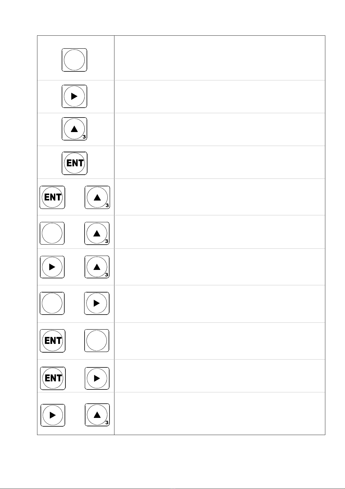
Key Switch
It is used when entering user setting mode from measurement mode.
It is used when exiting to measurement mode from user setting mode.
(ESC function)
It is used as location shift key when entering numerical value of user setting mode.
It is used as calibration mode entry key
It is used as check mode entry key
It is used as a key to increase and decrease the numerical value of selected
number line of user setting mode.
It is used as calibration mode entry key
It is used as check mode entr
y
ke
y
It is used when shifting to next menu from user setting mode.
It is used to save or exit after entering various setting values.
It is used as calibration mode entry key.
+
It is used for zero setting.
(No.3 key while pushing No.4 key or No,.4 key while pushing No.3 key)
+
It is used when entering function mode.
(No. 3 key while pushing No.1 key or No.1 key while pushing No. 3 key)
+
It is used when entering calibration mode.
(No.3 key while pushing No.,2 key or No,.2 key while pushing No.,3 key)
+
It is used when entering relay setting mode.
(No.2 key while pushing No.1 key or No.1 key while pushing No,.2 key)
+
It is used when entering hold mode.
Hold is cancelled when pushing this key once again.
(No.1 key while pushing No.4 key or No.4 key while pushing No.1 key)
+
It is used for key Lock or unlock.
Lock/ unlock is repeated ever time you push this key.
(No.2 key while pushing No.4 key or No.4 key while pushing No.2 key)
Power OFF
+
Power ON
It is used when entering check mode.
Turn the power on when pushing two keys at once after turning off the power
(No.2 key and No.3 key at once)
Itdoesnotmatterwhetheryoupushonekeybeforeanotherortwokeysatonceincaseofmodetoenterby
pushingtwokeys.

9
EXC +
EXC
COM2
L 3
L 2
L 1
ZERO
COM1
HOLD
6
INPUT OUTPUTLOAD CELL
78910
11 1212345
+-+-
CURR VOLT
AC85~AC240V
48Hz~63Hz
+
EXC +
EXC
COM2
L 3
L 2
L 1
ZERO
COM1
HOLD
6
INPUT OUTPUTLOAD CELL
78910
11 1212345
+-+-
CURR VOLT
AC85~AC240V
48Hz~63Hz
+
EXC +
EXC
COM2
L 3
L 2
L 1
ZERO
COM1
HOLD
6
INPUT OUTPUTLOAD CELL
78910
11 1212345
AC85~AC240V
48Hz~63Hz
+
EXC +
EXC
COM2
L 3
L 2
L 1
ZERO
COM1
HOLD
6
INPUT OUTPUTLOAD CELL
78910111212345
+-+-
CURR VOLT
AC85~AC240V
48Hz~63Hz
+
Load Cell Input/Output
Option
Grounding
Power
Serial Output
Connection
5. Description on Rear Panel
[StandardSpecification][AnalogOutputOption][BCDOutputOption]
5-1 Description on Each Terminal Unit
5-1-1 Power (AC IN)
Terminal No. Name Contents
L AC IN Power Input Terminal
N AC IN Power Input Terminal
F.G Frame Ground Frame Ground
Access to AC power code is conducted. Input power is AC85~240V and 50/60Hz.
10
EXC +
EXC
COM2
L 3
L 2
L 1
ZERO
COM1
HOLD
INPUT OUTPUTLOAD CELL
+-+-
CURR VOLT
AC85~AC240V
48Hz~63Hz
+
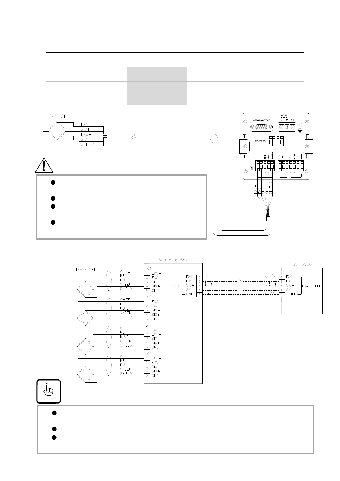
5-1-2 LOAD CELL Connection (1) (2) (3) (4) (5)
Terminal No. Name Contents
1 EXC + Load Cell Voltage (+), Red wire
2 EXC - Load Cell Voltage (-), White wire
3 SIG + Load Cell Input Voltage (+), Green wire
4 SIG - Load Cell Input Voltage (-), Blue wire
5 SHIELD Load Cell Grounding
Warning
Loadcelloutputisveryweakthusloadcellcableshallbe
separatedandtheninstalled.
Pleaseuseshieldcableforloadcellcable.
Incaseofextendingtheloadcellcable,useofloadcellcable
ofourcompanyisrecommended.
ShieldcableofloadcellcableshallbeconnectedtoBS‐3520
terminalonly.
Incaseofsealing,roadcellinputcableSIG+(green)andSIG‐(blue)cableshallbeconnectedtoNo.4and
No.3respectively
.
Theremaybeabnormalityinrelayoperationandoptionoutputwhentheweightisdisplayedin(‐)value.
Pleasecheckwhetherornotcolorofcableforeachmanufacturer’sandloadcellmodelis
differentornotbeforetheconnection.

11
5-1-3 Input (6) (7) (8)
Terminal No. Name Contents
6 ZERO Control terminal of zero function
Valid from COM1 terminal and short circuit (or on coin)
7 HOLD Control terminal of hold function
Valid from COM1 terminal and short circuit (or on coin)
8 COM1 Common terminal of external control
Relay contact or switch or contactless switch such as
Open collector output shall be used.
Arbitrary point hold is conducted at the point of granting
external contact point.
Hold is cancelled when grating the contact point.
PK hold only holds max value during the time contact point
is granted and it is cancelled when contact point is not
granted.
5-1-4 Output (9) (10) (11) (12)
Terminal No. Name Contents
9 L1 LO (RY1) relay output terminal (a, b contact point output based on mode setting)
10 L2 OK (RY2) relay output terminal (a, b contact point output based on mode setting)
11 L3 HI (RY3) relay output terminal (a, b contact point output based on mode setting)
12 COM2 Common terminal for relay output
Output method differs based on relay mode setting.
Refer to relay operation mode.
Relay contact point capacity is 5A 250VAC,
5A 30VDC.
5-1-5 Serial Output
They are RS-232C/ RS-422/ RS-485 output port. (basic equipment)
5-1-6 Option (DAC/BCD OUTPUT)
They are Analog Output DC 0~±5V, 0~±10V, DC 0~20mA, 4~20mA output terminal.
(Selection from function mode)
BCD Parallel Output, Analog Output option is equipped upon selection.
BCD Parallel Output option and Analog Output option cannot be equipped at the
same time.

12
5-2 How to Use Terminal Block and Replace Fuse
5-2-1 How to use terminal block
1) Peel off the sheath at the end of cable.
2) Terminal is opened when putting driver inside the terminal opening device
(top of terminal) and push upward.
3) Terminal is fastened when inserting the cable and pulls back the driver.
Forcedentryofcabletoterminalmaycausethedamageofterminal.
Donotinsertcabletotopofterminaltoinsertdriver.
5-2-2 How to replace fuse
1) Loosen the bolt of rear panel and pull off PCB as illustrated in the figure.
2) Replace the fuse. (Fuse Capacity: 250V 1.0A 20mm)
3) Assembly shall be conducted in reverse of disassembly.
Warning
Itshallbeconductedonlywhenthepoweristurnedoff.
EXC +
EXC
COM2
L 3
L 2
L 1
ZERO
COM1
HOLD
6
INPUT OUTPUTLOAD CELL
7 8 9 10 11 1212345
+-+-
CURR VOLT
AC85~AC240V
48Hz~63Hz
+
Screw
Fuse
13
2
123
4
M1
M1
M1 2 3 4
LO
LOW HIGH
OK HI HOLD ZERO
BS DIGITAL INDICATOR
-3520
M1 2 3 4
LO
LOW HIGH
OK HI HOLD ZERO
BS DIGITAL INDICATOR
-3520
M1 2 3 4
LO
LOW HIGH
OK HI HOLD ZERO
BS DIGITAL INDICATOR
-3520
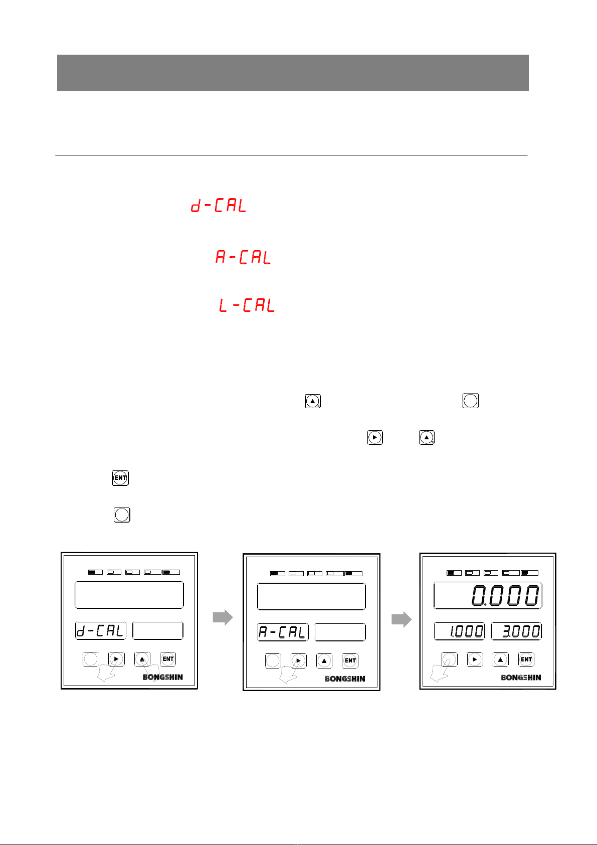
6. CALIBRATION
There are 3 types of calibration mode.
6-1 Calibration Mode
6-1-1 Mode
■Digital calibration mode
Calibration shall be conducted not by using the actual load but entering rated output and
rated capacity of sensor with key.
■Actual load calibration mode
It is calibration mode to adjust zero and span with the use of actual load.
■Linearization calibration mode
It is calibration mode to conduct non-linear calibration that reduces the measurement error
through calibration of maximum 4 points excluding zero with the use of actual load
6-1-2 How to select calibration mode
1. It turns into the mode selection status when key is pushed while pushing key is
pushed at measurement status.
2. Mode change and setting value change is available when key or key is pushed at
mode selection status.
3. Push key in order to move onto next stage after saving
the setting value at mode selection status.
3. Push key to cancel the setting and return to measurement mode for mode cancellation.
It is displayed as figure
when pushing no.3 key
while pushing no.2 key.
Change the mode with
No.2 or No.3 key.
(
d-CAL→A-CAL→L-CAL)
Push No.1 key for mode
cancellation.
14
123
123
456
M1 2 3 4
LO
LOW HIGH
OK HI HOLD ZERO
BS DIGITAL INDICATOR
-3520
M1 2 3 4
LO
LOW HIGH
OK HI HOLD ZERO
BS DIGITAL INDICATOR
-3520
LO
LOW HIGH
OK HI HOLD ZERO
BS DIGITAL INDICATOR
-3520
M1 2 3 4
12
LO
LOW HIGH
OK HI HOLD ZERO
BS DIGITAL INDICATOR
-3520
M1 2 3 4
12
LO
LOW HIGH
OK HI HOLD ZERO
BS DIGITAL INDICATOR
-3520
M1234 M1 2 3 4
LO
LOW HIGH
OK HI HOLD ZERO
BS DIGITAL INDICATOR
-3520
M1 2 3 4
LO
LOW HIGH
OK HI HOLD ZERO
BS DIGITAL INDICATOR
-3520
M1 2 3 4
LO
LOW HIGH
OK HI HOLD ZERO
BS DIGITAL INDICATOR
-3520
M1 2 3 4
LO
LOW HIGH
OK HI HOLD ZERO
BS DIGITAL INDICATOR
-3520
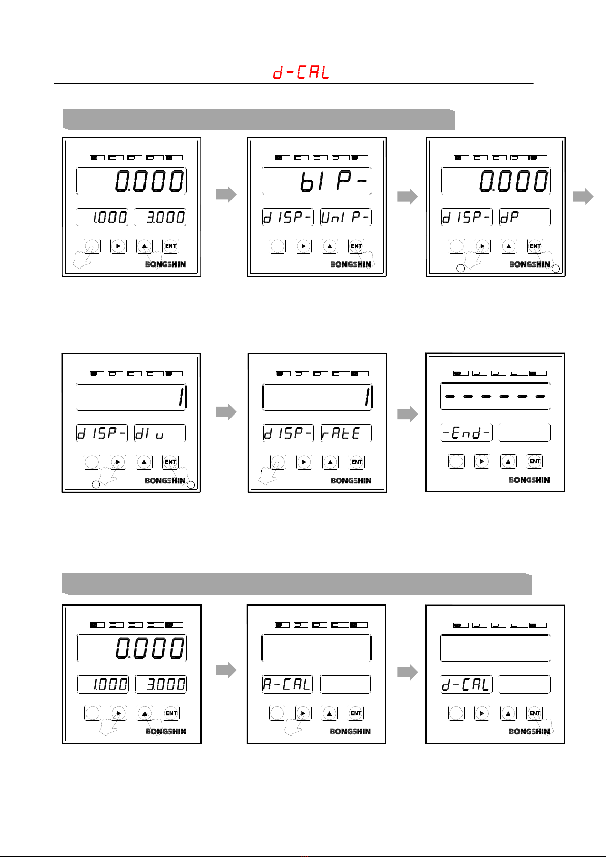
6-2 Digital calibration mode
6-2-1 Calibration Method
Step 1. Decimal point setting and min. gradation setting
When you push No.3 key while
pushing No.1 key, entry to
function mode is available.
It is changed to decimal point
mode when you push No. 4
key.
Push No.4 key by changing
decimal point by pushing No.2
or No.3 key.
Input is completed when yo
u
push No.4 key after changing
Min, unit with the use of
either No.2 or No.3 key.
It is changed in measuremen
t
mode when you push No. 1
Key.
Decimal point change and
minimum unit change have
been completed.
Step 2. Rated output and capacity setting of Load Cell
Push No.3 key while pushing
No,2 key.
Change the mode to d-CAL
with either No.2 or No.3 key.
Enter into d-CAL mode by
pushing No.4 key

15
56
12
4
M1 2 3 4
LO
LOW HIGH
OK HI HOLD ZERO
BS DIGITAL INDICATOR
-3520
12 3
M1234
LO
LOW HIGH
OK HI HOLD ZERO
BS DIGITAL INDICATOR
-3520
12
LO
LOW HIGH
OK HI HOLD ZERO
BS DIGITAL INDICATOR
-3520
M1234
M1 2 3 4
LO
LOW HIGH
OK HI HOLD ZERO
BS DIGITAL INDICATOR
-3520
M1 2 3 4
LO
LOW HIGH
OK HI HOLD ZERO
BS DIGITAL INDICATOR
-3520
LO
LOW HIGH
OK HI HOLD ZERO
BS DIGITAL INDICATOR
-3520
M1234
LO
LOW HIGH
OK HI HOLD ZERO
BS DIGITAL INDICATOR
-3520
M1234
Input load cell rated output
using No. 2 and No.3 key and
Push No.4 key.
(Ex: 2.0000 mV/V)
Input rated capacity of load cell
with the use of No.2 and No,.3
key.
(ex: 15.000 kg)
Digital input is completed when
pushing No.4 key and it returns
to measurement mode.
Step 3. Zero Calibration
Push No.3 key while pushing
No.4 key.
Zero calibration is
completed.
Warning
Althoughthesettingrangeofresolutionis1/20000orlowerbutdisplayisconductedevenwhenit
exceeds20000.
Errormaygeneratefordigitalcalibrationmode.
Conductregularcheckonmeasurementandconductcalibrationuponnecessity.
Calibrationunderinstableenvironmentmaycausethemeasurementerror.

16
123
123
456
M1 2 3 4
LO
LOW HIGH
OK HI HOLD ZERO
BS DIGITAL INDICATOR
-3520
M1 2 3 4
LO
LOW HIGH
OK HI HOLD ZERO
BS DIGITAL INDICATOR
-3520
LO
LOW HIGH
OK HI HOLD ZERO
BS DIGITAL INDICATOR
-3520
M1 2 3 4
12
LO
LOW HIGH
OK HI HOLD ZERO
BS DIGITAL INDICATOR
-3520
M1 2 3 4
12
LO
LOW HIGH
OK HI HOLD ZERO
BS DIGITAL INDICATOR
-3520
M1234 M1 2 3 4
LO
LOW HIGH
OK HI HOLD ZERO
BS DIGITAL INDICATOR
-3520
M1 2 3 4
LO
LOW HIGH
OK HI HOLD ZERO
BS DIGITAL INDICATOR
-3520
M1234
LO
LOW HIGH
OK HI HOLD ZERO
BS DIGITAL INDICATOR
-3520
M1 2 3 4
LO
LOW HIGH
OK HI HOLD ZERO
BS DIGITAL INDICATOR
-3520
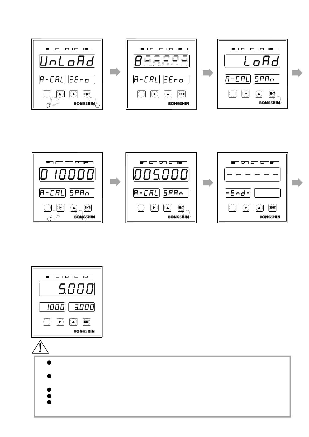
6-3 Actual load calibration mode
6-3-1 Calibration Method
Step 1. Decimal point setting and min. gradation setting
Entry to function mode is
available when pushing No.3
key while pushing No.1 key.
It changes to decimal point
mode when pushing No.4 key.
Push No. 4 key after changing
decimal point by pushing
either No.2 or No.3 key.
Input is completed when yo
u
No.4 key after changing min
unit by pushing either No.2
or No.3 key.
It returns to measurement
mode when pushing No. 1 key.
Decimal point change and
min. unit change have been
completed.
Step 2. Zero calibration and dead weight setting
Push No.3 key while pushing
No. 2 key.
Change the mode to A-CA
L
with either No.2 or No.3 key.
Enter into A-CAL mode by
pushing No.4 key.
17
456
10
789
M1 2 3 4
LO
LOW HIGH
OK HI HOLD ZERO
BS DIGITAL INDICATOR
-3520
12
LO
LOW HIGH
OK HI HOLD ZERO
BS DIGITAL INDICATOR
-3520
M1 2 3 4
LO
LOW HIGH
OK HI HOLD ZERO
BS DIGITAL INDICATOR
-3520
M1 2 3 4
LO
LOW HIGH
OK HI HOLD ZERO
BS DIGITAL INDICATOR
-3520
M1 2 3 4
12
LO
LOW HIGH
OK HI HOLD ZERO
BS DIGITAL INDICATOR
-3520
M1234 M1 2 3 4
LO
LOW HIGH
OK HI HOLD ZERO
BS DIGITAL INDICATOR
-3520
M1 2 3 4
LO
LOW HIGH
OK HI HOLD ZERO
BS DIGITAL INDICATOR
-3520
Select Unload among Load and
Unload with the use of No.2
and No.3 key and push No.4
key when there is nothing on
load cell.
Conduct zero calibration.
It is changed to dead weigh
t
value mode when pushing
No. 4 key after load display.
Input dead weight value with
the use of No. 2 and No,.3
key. Ex) 5.000kg
Push No.4 key after exerting
actual load to load cell.
ErrO is played and it is turned
to LoAd status when load is
small or direction of load is
applied toward (-) direction.
Actual load calibration has
been completed.
Check the dead weight value indicated to display.
Check the zero point return status after lowering the dead weight and
Step2 shall be executed repeatedly when there is abnormality.
Warning
Displayspeedshallbesetasslowaspossibleinfunctionmodeduringcalibrationinorderto
displaystablevalue.
Althoughresolutionsettingrangeis1/20000orlower,displayisstillconductedwhenitexceeds
20000.
Conductregularcheckonmeasurementandconductcalibrationuponnecessity.
Calibrationunderinstableenvironmentmaycausethemeasurementerror.
Itisrecommendedthattheuseofdeadweightwithover2/3ofmaxcapacityisrecommended
inordertoreducetheerror.
18
123
456
M1 2 3 4
LO
LOW HIGH
OK HI HOLD ZERO
BS DIGITAL INDICATOR
-3520
M1 2 3 4
LO
LOW HIGH
OK HI HOLD ZERO
BS DIGITAL INDICATOR
-3520
LO
LOW HIGH
OK HI HOLD ZERO
BS DIGITAL INDICATOR
-3520
M1 2 3 4
12
LO
LOW HIGH
OK HI HOLD ZERO
BS DIGITAL INDICATOR
-3520
M1 2 3 4
12
LO
LOW HIGH
OK HI HOLD ZERO
BS DIGITAL INDICATOR
-3520
M1234 M1 2 3 4
LO
LOW HIGH
OK HI HOLD ZERO
BS DIGITAL INDICATOR
-3520
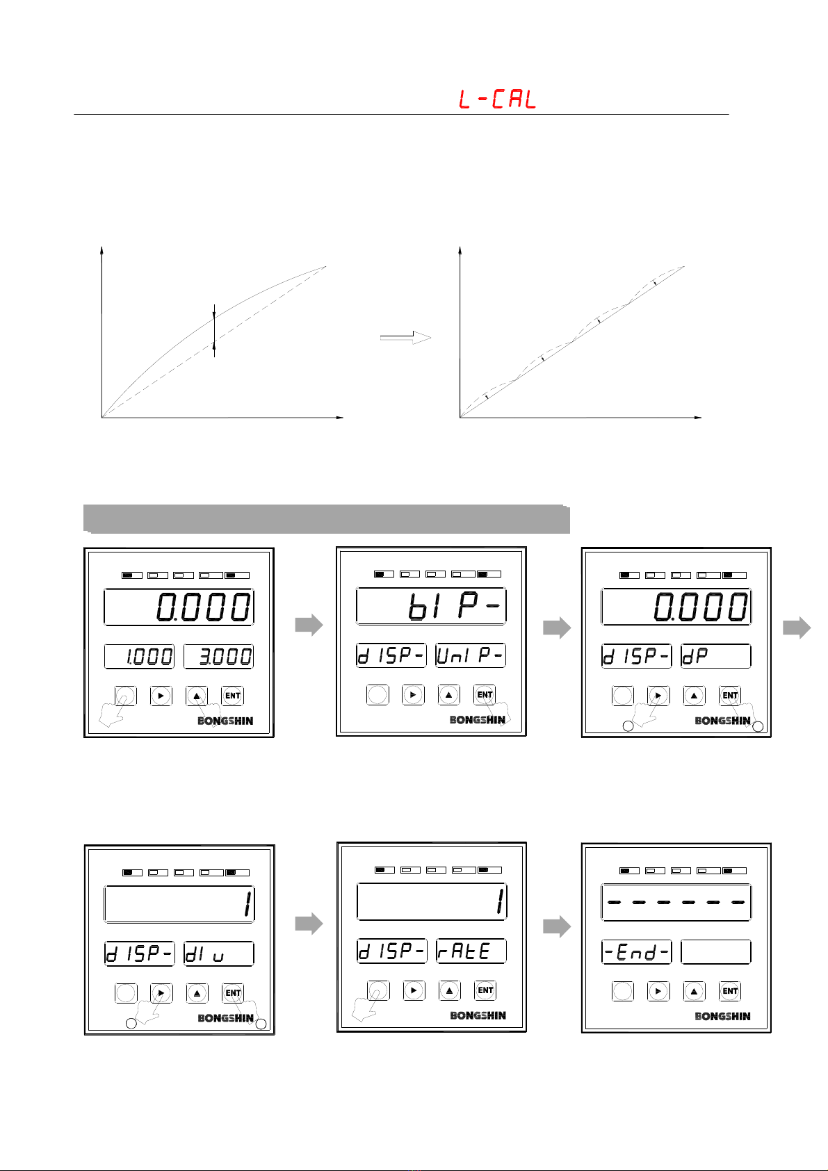
6-4 Linearization Calibration Mode
6-4-1 Calibration Method
A little measurement error may occur in between the max capacity due to trait of measurement
unit even upon the completion of zero and span calibration. Linearization calibration mode is a
type of calibration mode which conducts non-linear calibration that reduces the measurement
error by conducting calibration with max 4 points excluding the zero with the use of actual load.
ZERO
0 Weight Value
Display
Error
ZERO
Before linear compensation After linear compensation
0 Weight Value
Display
Calibration point 1 (Load1)
Calibration point 2 (Load2)
Calibration point 3 (Load3)
SPANSPAN
Step 1. Decimal point setting and min gradation setting
Enter into function mode by
pushing No.3 key while
pushing No.1 key.
It is changed to decimal point
mode when pushing No. 4 key.
Push No.,4 key after changing
decimal point by pushing
either No.2 or No.3 key.
Input is completed when you
push No.4 key after changing
min unit by pushing either
No.2 or No.3 key.
It is changed to measurement
mode when pushing No.1 key..
Decimal point setting and min.
unit setting have been
completed.

19
123
456
789
M1 2 3 4
LO
LOW HIGH
OK HI HOLD ZERO
BS DIGITAL INDICATOR
-3520
M1234
LO
LOW HIGH
OK HI HOLD ZERO
BS DIGITAL INDICATOR
-3520
M1 2 3 4
LO
LOW HIGH
OK HI HOLD ZERO
BS DIGITAL INDICATOR
-3520
M1 2 3 4
LO
LOW HIGH
OK HI HOLD ZERO
BS DIGITAL INDICATOR
-3520
M1234
LO
LOW HIGH
OK HI HOLD ZERO
BS DIGITAL INDICATOR
-3520
M1 2 3 4
LO
LOW HIGH
OK HI HOLD ZERO
BS DIGITAL INDICATOR
-3520
12
M1 2 3 4
LO
LOW HIGH
OK HI HOLD ZERO
BS DIGITAL INDICATOR
-3520
12 3
M1 2 3 4
LO
LOW HIGH
OK HI HOLD ZERO
BS DIGITAL INDICATOR
-3520
12 3
M1 2 3 4
LO
LOW HIGH
OK HI HOLD ZERO
BS DIGITAL INDICATOR
-3520
Step 2. Zero calibration and dead weight setting
Push No.2 key while pushing
No.3 key .
It is changed into L-CAL mode
when pushing either No.2 or
No.3 key.
Enter into L-CAL mode by
pushing No.4 key.
Check the stability after
display of UnLoad and
push No.4 key when there
is nothing on load cell.
Conduct zero calibration.
Input dead weight value by
using No.2 and No.3 key
after entering 1st dead weight
to measurement unit with
display of Load 1.
1st dead weight value is
stored when you push No.4
key after checking the
stability.
Push No.4 key after entering
the dead weight value with
use of No.2 and No.3 key
and entering 2nd dead
weight upon display of
Load2.
Push No.4 key after entering
the dead weight value with
the use of No.2 and No.3
key and entering 3rd dead
weight upon display of
Load3.
Table of contents
Other Bongshin Touch Panel manuals


