Bongshin BS-8300 Quick start guide


1
7CBH9BHG
DF9:579""""""""""&
H97<B=75@ GD97=:=75H=CB " " )
8=A9BG=CBG"""""""""""""+
:FCBHD5B9@"""""""""""",
F95FD5B9@"""""""""""""" %&
=BGH5@@5H=CB"""""%)
75@=6F5H=CB AC89 5WhiU`
"%*
75@=6F5H=CB AC89 G]ai`Uh]cb
&&
G9H!IDAC89"""""""""""&+
G9F=5@=BH9F:579""""""""')
7CBHFC@@=B; K9=;<H " " " " " (%
9ffcfAYggU[Y
5bX HfciV`Y G\cch]b[ " " " ((

2
DF9:579
%"=BHFC8I7H=CB
Thank you very much for your purchasing BONGSHIN Digital Weighing
Indicator of BS-8300.
This Instruction Manual will lead you to use BS-8300 with top reliability,
High speed, high accuracy.
BS-8300 is Digital Weighing Indicator amplifying the analog output from a
load Cell, converting the analog signal to digital data and then displaying
this data
As a weight reading and is designed for flawless performance in your
demanding
Application of input-weighing, output-weighing, accumulating-weighing,
2step control.
Also, an additional option will make Modern Industry demand equipment
that both versatile
And availed to easily connect to other devices
※ Example for application :
1. PACKING EQUIPMENTS FOR MANUAL WEIGHING
2. EQUIPMENTS FOR AUTO-FILLER WEIGHING
3. EQUIPMENTS FOR OUTPUT WEIGHING
4. EQUIPMNETS FOR ACCURACY WEIGHING
5. RECORD-MANAGEMENT FOR PRODUCT WEIGHT
☞ REMARK
- Specification subject to change for improvement without prior notice.
- If changing, the Version No can be increased, but keeps a former
version
As far as possible

3
&"G5:HM7CB8=H=CBG
Please keep the following using conditions certainly
■
EARTH
To avoid an electric error such as a noises in your production line
It should be earthed before installation certainly.
Specially it will be safety to divide the power of Indicator into a load cell.
■
SAFTY CONDITIONS
Don’t use it closed to a explosive gas and an inflammable dust
environments
■
POWER
Use the power under 110/220V 50/60HZ ±10% and divide it into the
power line
■
TEMPERTURE CONDITIONS
Operating Temperature : -10o C ∼ +40o C ( +14o to 104
o F )
Custody Temperature : -40o C ∼ +80o C ( -40o to 176
o F )
■
INSTALLATION LOAD CELL
- Available to use the same load cell of 6pcs ( 350Ω standard )
- A ground should be installed horizontal
-Installing over 2pcs of load cell, please connect each line in parallel
and Insert a variable resistor under 50Ω in EX + line and minimize a output
Accuracy of load cell.
It may occur a weight error by each accuracy of load cell.
-
It may occur a weight error in case of a temperature variation of load cell
-
Please weld(elect spark) at the place installed with load cell and equipments,
Divide the power into a connector of load cell in inevitable case
-
Please connect the below construction of load cell with the above ones using
The earth to the weighing part weighing a material occurring a electro sparks.

4
'":YUhifYg
-
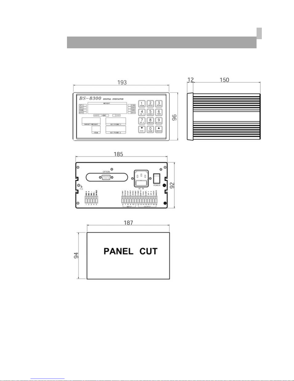
A compact Appearance by DIN regulations ( DIN 193 x 96 Panel system )
- Easy to preset, change, confirm the weight value by the numeral key.
- Improved a convenience and precision of operating with Message
Function.
- Can use or disuse each key function. (SETUP Reference)
- Weight Memory function even in electro spark case.
- Watch-Dog timer guards for self-diagnostics.
- Set up to 1/20,000 display resolution
- Function available to change the unit value such as g,
kg, ton.
( In case of Serial Communication & Printer )
- Various specification of weight conversion speed.
(Digital Filter Function)
- Various option and addition for customer’s satisfaction such as serial
communication, RS-422, Printer, BCD Input and so on.
5
H97<B=75@GD97=:=75H=CB
%"5bU`c[=bdih5#87cbjYfg]cb
@cUXWY``YlW]hUh]cb
Jc`hU[Y
DC 10V ±5%, 300㎃
up to 8 x 350ohm load cells
=bdihgYbg]h]j]hm 0.3 μV/D
GmghYa`]bYUf]hm Within 0.01% F.S.
NYfcUX^ighfUb[Y -1㎷ ~ +34㎷
=bdihJc`hU[Y Max. 34㎷ Min. 5㎷
5WWifUWm Zero drift : ±0.2 μV/℃ RTI max.
Span drift : 20ppm/℃ max.
=bdihBc]gY ±0.3 μV p.p or less
=bdih=adYXUbWY 10 ㏁ (Min.)
5#8WcbjYfhYf Sigma-Delta system
5#8]bhYfbU`fYgc`ih]cb Approximately 200,000 counts
5#8YlhYfbU`fYgc`ih]cb 1/20,000 (Max.)
5#8WcbjYfg]cbgdYYX 50 times/sec
AUl"fYgc`ih]cb 1/20,000
&"8][]hU`DUfh
8]gd`Um 7 Segment LED,
6-Digits, 14.1mm(Height)
8]gd`UmVY`cknYfc “-”minus signal
5XX]h]cbU`gmaVc`g Zero, Stable, Gross, SP1, SP2, AUTO,
RUN, UNDER, OVER
A]b"8]j]g]cb x1, x2, x5, x10, x20, x50, x100
8YW]aU`Dc]bh 0, 0.0, 0.00, 0.000, 0.0000

6
'"HYW\b]WU`
57UXUdhYf AC 110/220V ±10%, 50/60Hz
DckYfWcbgiadh]cb 30 VA
8UhUAYacfm 10 year
CdYfUh]b[hYadYfUhifY
-10℃~+40℃ (+14℉ ~ +104℉ )
<ia]X]hm 85% Rh Max.
CjYfU``X]aYbg]cbg 193(W) x 162(D) x 96(H)
KY][\h 2.5 kg
("Cdh]cb
Cdh]cb–% Serial Interface : RS-232C
Cdh]cb–& Serial Interface : RS-422
Cdh]cb–' Parallel Interface : BCD INPUT
7
8=A9BG=CBG
8
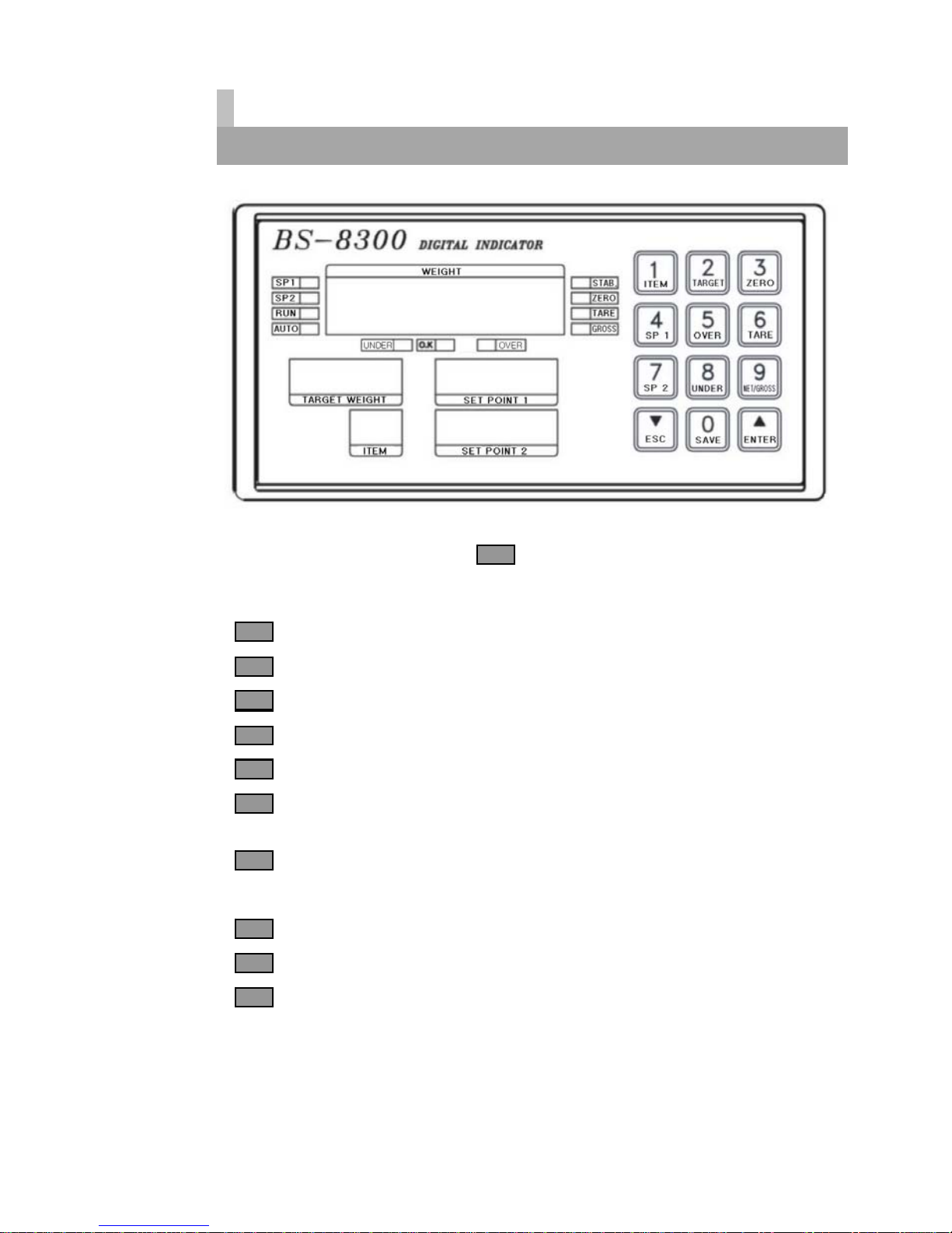
:fcbhDUbY`
%"8]gd`Um@Uad
GD%@Uad: : It will lamp when 1step(90%) control works
GD&@Uad: : It will lamp when 2step(100%) control works
FIB@Uad: ON when the weighing is run.
GH56@9@Uad : ON when the weight is stable.
N9FC`Uad: ON when the current weight is 0 kg.
H5F9@Uad : ON when the tare weight is stored.
This Lamp will be switched to Net mode
;FCGG@Uad : ON when the current weight is GROSS weight.
When presetting a TARE, It will be a Lamp Function.
IB89F@Uad:
C"?@Uad:
CJ9F@Uad:
9
&"?YmVcUfX
* The Key operating can be permitted or prohibited by SETUP-F10
* When pushing the key, it sounds "OK".
* Each Key works either a single function or compound functions.
A compound function key will be a command key when it push first
and According to the command key, the fixed value works its function,
The key to finish a input data is ENTER Key.
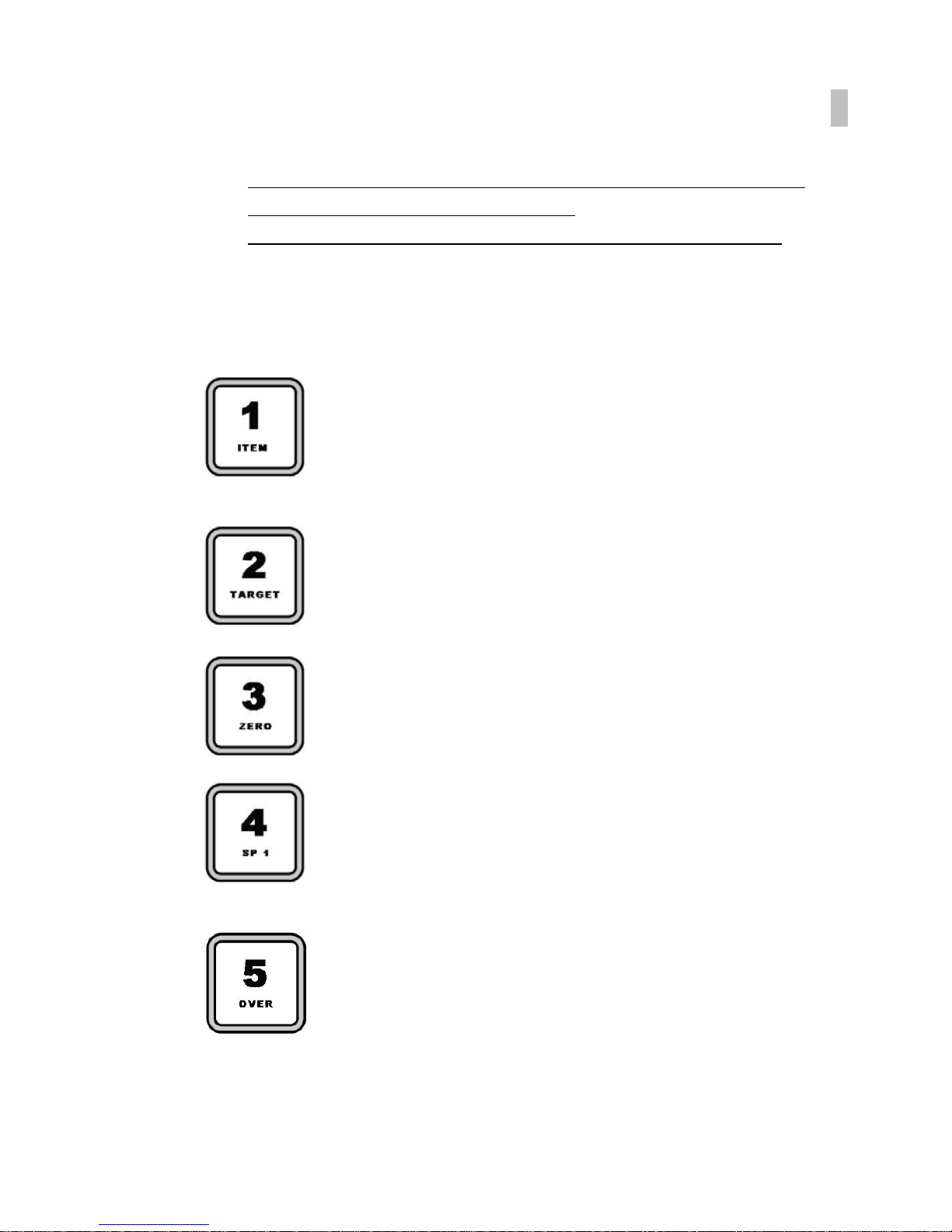
ITEM Key : Usable to confirm or change the product part
* Can set up the data of each product from 1 No to 50 No.
- Confirmation ITEM : ITEM Key → ESC Key
- Changing ITEM : ITEM Key → Numeral Key →ENTER key
TARGET Key : Usable to confirm or change the target weight.
- Confirmation TARGET : TARGET Key → ESC Key
- Changing TARGET : TARGET Key → Numeral Key →ENTER key
ZERO Key : This key returns the display to the center of
ZERO when the weighing device is empty
- Changing ZERO : ZERO Key →ENTER key
SP 1 Key : Set Point 1(90%)weight.
-Confirmation SP1 : SP1 Key → ESC Key
-Changing SP1 : SP1 Key → Numeral Key →ENTER key
OVER Key : OVER weight.
-Confirmation OVER : OVER Key → ESC Key
-
Changing OVER : OVER Key → Numeral Key →ENTER key

10
TARE Key
1. Set-up of TARE Key
① Put a TARE on the weighing plate
② TARE Key → SET Key
2. Remove of TARE Key
① Remove TARE on the weighing plate
② Push TARE Key and push ENTER Key.
SP 2 Key : Set Point 2(100%) weight.
-Confirmation SP2 : SP2 Key → ESC Key
-Changing SP2 : SP2 Key → Numeral Key →ENTER key
UNDER Key : UNDER weight.
-Confirmation UNDER : UNDER Key → ESC Key
-
Changing UNDER : UNDER Key → Numeral Key →ENTER key
NET/GROSS Key
After setting TARE, Net Weight converts Gross weight,
or Gross weight converts Net Weight
* Available to convert setting TARE only.
SAVE Key
When recording each sated data
SAVE Key →ENTER key
ESC Key
This have 2way to use as follows .
1) When canceling it with input the setting value
2) Change the set Point 2 value
Decrease the first place value to 1.

11
ENTER Key
This have 2way to use as follows .
1) When canceling it with input the setting value
2) Change the set Point 2 value
Increases the first place value to 1.
12
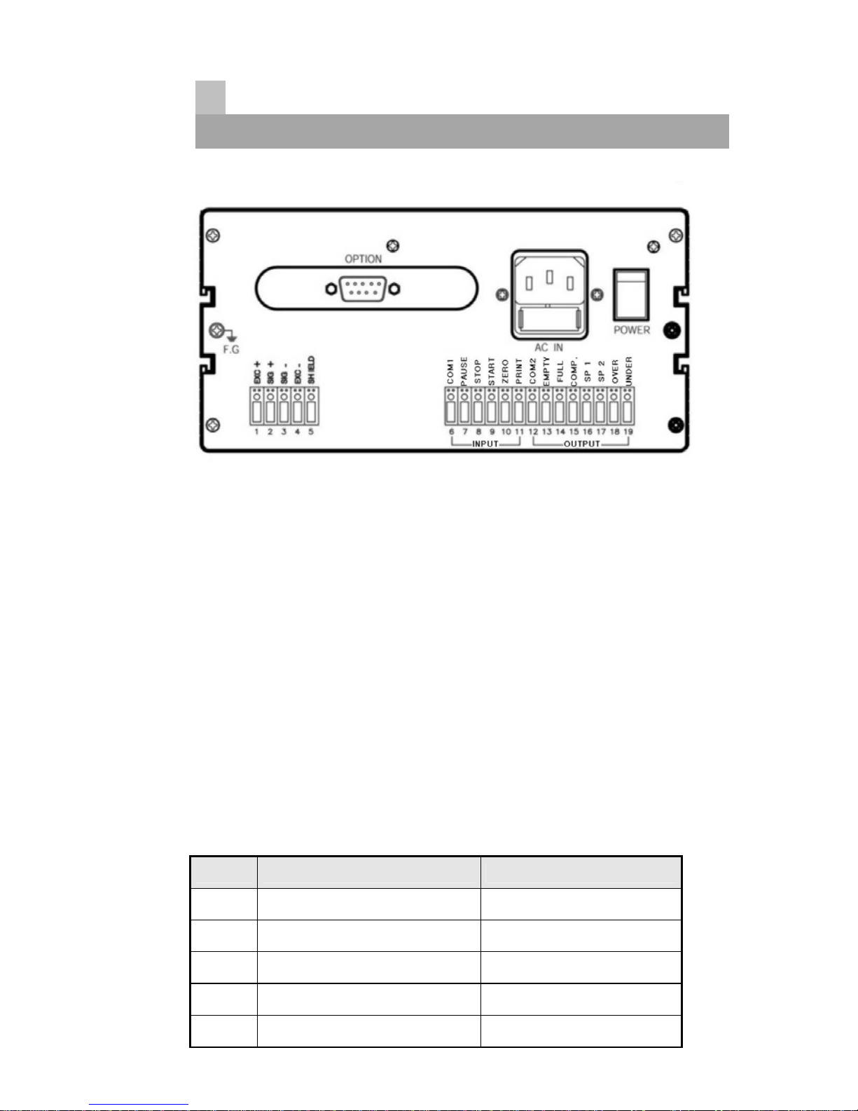
FYUfDUbY`
■ DCK9F : Power ON, OFF switch
It will be safe to use it after 10minuate for a precise measurements.
■ 57=B : Available to change AC110/220V with multiple.
Before setting up, please confirm the power voltage.
Please change the connect terminal of 110V/220V after
opening the cover
If you need to change. (It was settled with AC220V at the first)
Use a stable power supply AC110/220V ±10%, 50/60Hz
■ :IG9 : please use the standard approved .
FUSE AC250V, 0.5A (a glass tube with small type)
■ :"; : Please earth it for safe.
■ @C5879@@ Please connect the indicator connector with the wire of
load cell according to the color.
Pin no. SIGNAL
1 Load cell Input Voltage (+) EXC+ (Red)
2 Load cell output (+) SIG+ (Green)
3 Load cell output (-) SIG- (Blue)
4 Load cell Input Voltage (-) EXC- (White)
5 Shield SHIELD

13
EXC+
EXC-
SIG+ SIG-
SIG- (Blue)
EXC- (White)
SHIELD
SIG+ (Green)
EXC+ (Red)
1
2
3
4
5
The wire color of load cell according to a manufactures.
1
EXC+
2
EXC-
3
SIG+
4
SIG-
5
SHIELD
6CB;G<=B F98 K<=H9 ;F99B 6@I9 G<=9@8
CAS, TMI, AND RED WHITE GREEN BLUE SHIELD
BLH GREEN BLACK WHITE RED YELLOW
INTERFACE RED BLACK GREEN WHITE SHIELD
KYOWA RED BLACK GREEN WHITE SHIELD
P.T. RED BLACK GREEN WHITE SHIELD
SHOWA RED BLUE WHITE BLACK SHIELD
SHINKOH RED BLACK GREEN WHITE SHIELD
TML RED BLACK WHITE GREEN SHIELD
TFAC RED BLUE WHITE BLACK YELLOW
HUNTLEIGH GREEN BLACK RED WHITE SHIELD
※ Because wire color may be different according to a manufacture and
load cell models. Please refer for the data sheet of load cell.

14
=B!DIH : COM1, PAUSE, STOP, START, ZERO, PRINT
This key is to control a equipment from the outside .
Please connect between COM terminal and each input terminal .
Because the power of input terminal was connected with 12V voltage
From the inside.
* An electric current is about 10mA.
* Please make the minimum time to input a data with over 50mSEC.
■ CIH!DIH : COM2, EMPTY, FULL, COMP, SP 1, SP 2, OVER, UNDER
Connect between COM terminal and OUTPUT terminal
With the earth of no electric power.
Please use the output data For a signal only, don’t use it for working.
Max earth capacity : AC250V / 0.5A
=bghU``Uh]cb

15
☞ GENEANL RULES
- Avoid sudden Collision, vibration, temperature, water, wind
- Use a stable power supply 110V/220V ± 10% 50/60Hz
Set up voltage 220V
(Adjust the power voltage because the choice terminal of power is inside.)
- Connect and power off the switch when connecting the external
equipments.
- Ensure to earth Indicator to equipments
- Ensure to calibrate and set up it for operating.
* PARTS
- POWER CODE : 1EA
- FUSE : 1EA (PIPE TYPE 250V 0.5A SMALL TYPE)
- OPERATING MANUAL : 1EA
- A Stable Connector for Option installation.
▶ H9FA=B5@6@C7?
ઔ:IG9
FUSE : AC250V, 500mA

16
7U`]VfUh]cbacXY5WhiU`kY][\h
▣ What is Calibration?
Calibration is to adjust max weight, minimum division, decimal point
displayed to Indicator
To the actual weight worked by load cell.
☞ It should calibrated certainly when load cell or indicator will be
changed.
%"GD5B58>IGHA9BH
▣ what is span adjustment.
Span adjustment is to make the display value from "0" to max weight
consistent to the actual weight.
%!% <ckhcUWWYggh\YGD5B58>IGHA9BH
Turn on the power while pushing Key then, the display will
be "SEt. CAL."
Also, pushing
ENTER KEY on the below right. it will be displayed with "d xx"
("xx" means 1, 2, 5, 10, 20, 50, 100)
예) POWER OFF CONDITIONS
1. While pushing e Key ---------- Display is "SEt. CAL."
2. Pushing ENTER key ---------- Display is "d 2"
☞ "SEt. CAL." means SETUP & CALIBRATION mode
%!& 5jU]`UV`Y?Ymg
S&C MODE have 6way to adjust span. each step will be advanced with
ENTER key. Also, ESC key was used to return the prior conditions.
※ F.F : ENTER key
※ Review : ESC key

17
%!' 7U`]VfUh]cbAYbi%GhYdr*GhYd
1 Step : Minimum Division Set
2 Step : Maximum Capacity Set
3 Step : Setting Weight in span calibration
4 Step : Zero Calibration
5 Step : Span Calibration
6 Step : END
GhYd%
- Function : A]b]aia8]j]g]cbGYh
Range → 1~ 100
A step to set up a division value.
"d" means "Division" and "xx" means a division capable of displaying.
Also this value will be displayed as 1-2-5-10-20-50-100 by each key.
A step to set up a Decimal point is Function mode.
So, it will be go to the next step recording the position.
Key Display Description
“SAVE” key :
Increase
“ENTER” key :
Store and move
Into next menu
SEt.CAL. condition.
1 kg (Decimal point : 0)
0.01kg (Decimal point: 2)
☞ REF 1.The minimum division means the value of one division.
☞ REF 2. External resolution is obtained by division the min. division by the
maximum capacity. Set the resolution to be within 1/30,000.

18
GhYd&
- Function : AUl]aia7UdUW]hmGYh
Range → 1 ~ 99,999kg
A step to set up max. weight.
The display will appear "CAP."(Capacity) and discretion number
"C1000.0." (max. 5figure)
It can input the maximum weight as the end-user demands instead of
discretion number.
How to input is to push ENTER key after inputting discretion number.
♣ Don’t excess (A division ÷ Max. weight) with over 1/20,000
If accessing over 1/20,000,it will appear "Err 01".
Key Display Description
“ENTER” key :
Store and move
into next menu
Step 2 condition.
100 kg
10000kg
☞ REF 1. The maximum capacity means the maximum weight that scale
can measure.
GhYd'
- Function : GYhh]b[KY][\h=bGdUb7U`]VfUh]cb
Range → 1~ 99,999kg
The display discretion number "L1000.0." (span 5figure)
Please input the value of standard weight for span adjustment by
numeric key.
How to input is to push
ENTER
key after inputting discretion number.
This value of span standard weight must be equal to full capacity,
19
or over 10% of full capacity.
( In case of less 1/5,000 resolution ,the value of standard weight
must be over 10% of full capacity at least.)
( In case of over 1/5,000 resolution ,the value of standard weight
must be over 20% of full capacity at least.)
(Notice) If span capacity is set less 10% , indicator will display
error message.
Key Display Description
“ENTER” key :
Store and move into
next menu
Step 3
100 kg
10000kg
Setting Weight
☞ REF 1.
The weight shall be within the range of 10%~100% of maximum weight.
☞ REF 2.
The setting weight must be over the range of 10% of maximum weight.
☞ REF 3.
The setting weight over the maximum capacity.
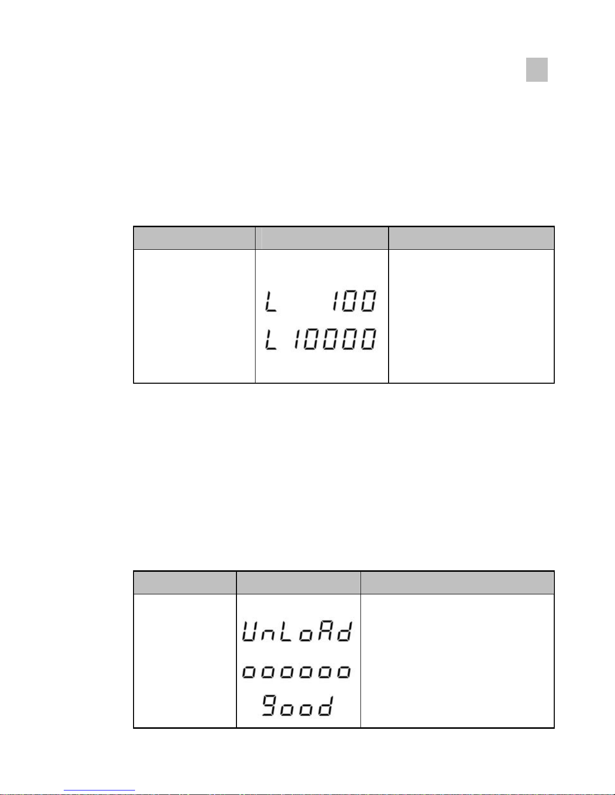
GhYd(
-Function : NYfc7U`]VfUh]cb
A step to check the zero conditions of Indicator.
After appearing "UnLoAd", please push ENTER key.
Please do it as the zero adjustment instruction.
Key Display Description
“ENTER” key :
Zero calibration
and move into
next menu
Step 4
Unload the tray and press
“ENTER”
key
Under zero calibration
Zero calibration is completed.
Table of contents
Other Bongshin Touch Panel manuals


Popular Touch Panel manuals by other brands


Emerson
Emerson GFK-3072D quick start guide

NENKO
NENKO Wallpanel Infinty quick start guide

Advantech
Advantech IPPC-8151S Series user manual

YASKAWA
YASKAWA VIPA HMI PPC021 CE manual

Extron electronics
Extron electronics TLP Pro 1725TG Setup guide

Extron electronics
Extron electronics SMK 2 installation guide