Bongshin BS-32 Quick start guide


1
7CBH9BHG
=BHFC8I7H=CBG""""""""""&
H<9 :95HIF9G " " """""""'
H97<B=75@ GD97=:=75H=CB " " (
8=A9BG=CBG""""""""""""")
:FCBHD5B9@""""""""""""" *
7CBB97H=CB""""""""""""+
65HH9FM IG5;9""""""""",
?9M6C5F8""""""""""""-
75@=6F5H=CB AC89 " " " " " %$
G9F=5@ =BH9F:579 """""%+
9ffcfAYggU[Y
5bX HfciV`Y G\cch]b[ " " " %-

2
=BHFC8I7H=CBG
%"=BHFC8I7H=CB
Thank you very much for your purchasing BONGSHIN Digital Weighing
Indicator of BS-32.
This Instruction Manual will lead you to use BS-32 with top reliability,
High speed, high accuracy.
BS-32 is Digital Weighing Indicator amplifying the analog output from a
load Cell, converting the analog signal to digital data and then
displaying this data
As a weight reading and is designed for flawless performance in your
demanding
Before using, It is recommended that you read this manual carefully so
you may use this device to its full potential.
&"DF975IH=CBG
■ Place the indicator on a flat and stable surface.
■ Do not severely press because the light pressing of keys can incite
the operation.
■ Do not subject the scale to sudden temperature changes.
Operating temperature : -10℃~+40℃
■ Keep the scale away from strong EMI noises may cause incorrect
weight readings.
■ Keep the main body from rain and keep in dry area.
■ Do not use inflammable materials in cleaning.

3
:95HIF9G
%":YUhifYg
■ Appropriate for weight and measurement system.
■ Easy operation and various options.
■ Simple full digital calibration.
■ Watchdog circuitry (system restoration)
■ Weight Back-up (power on actual weight)
&"AU]b:ibWh]cb
■ RS-232C Option
■ User can set the max. weight which users want to and division
at one’s disposal.
4
H97<B=75@GD97=:=75H=CB
5bU`c[ g][bU`=bdih fUb[Y 0mV ~ 20mV
Bcb!`]bYUf]hm 0.01% F.S. max.
AUl"8]gd`Um fYgc`ih]cb 1/10,000
A]b" =bdihgYbg]h]j]hm 0.3 μV/Digit
HYadYfUhifY 8f]Zh Zero drift : ±0.2 μV/℃ RTI max.
Span drift : 20ppm/℃ max.
@cUXWY``9lW]hUh]cb DC 5V,
350ohm x 1 load cell
=bdihBc]gY ±0.3 μV p.p or less
=bdih=adYXUbWY 10 ㏁ (Min.)
5#8WcbjYfhYf 24bit Sigma-Delta system
5#8]bhYfbU`fYgc`ih]cb Approximately 200,000 counts
5#8WcbjYfg]cbgdYYX 10 times/sec
8]gd`Um 7 Segment LCD,
4 1/2 Digits, 17.8mm(Height)
Dc`Uf]hm ]bX]WUh]cb! “-”minus sign
8]gd`Um ]bWfYaYbhg 1, 2, 5, 10, 20, 50 selectable
8YW]aU`Dc]bhg Selectable to any points
CdYfUh]b[ Jc`hU[Y Alkaline battery x 4 or Power adaptor
DckYfWcbgiadh]cb Approx. 5 VA
CdYfUh]b[hYadYfUhifY
-10℃ ~ +40℃
Cihdih RS-232C serial output
KY][\h Approx. 410g
5
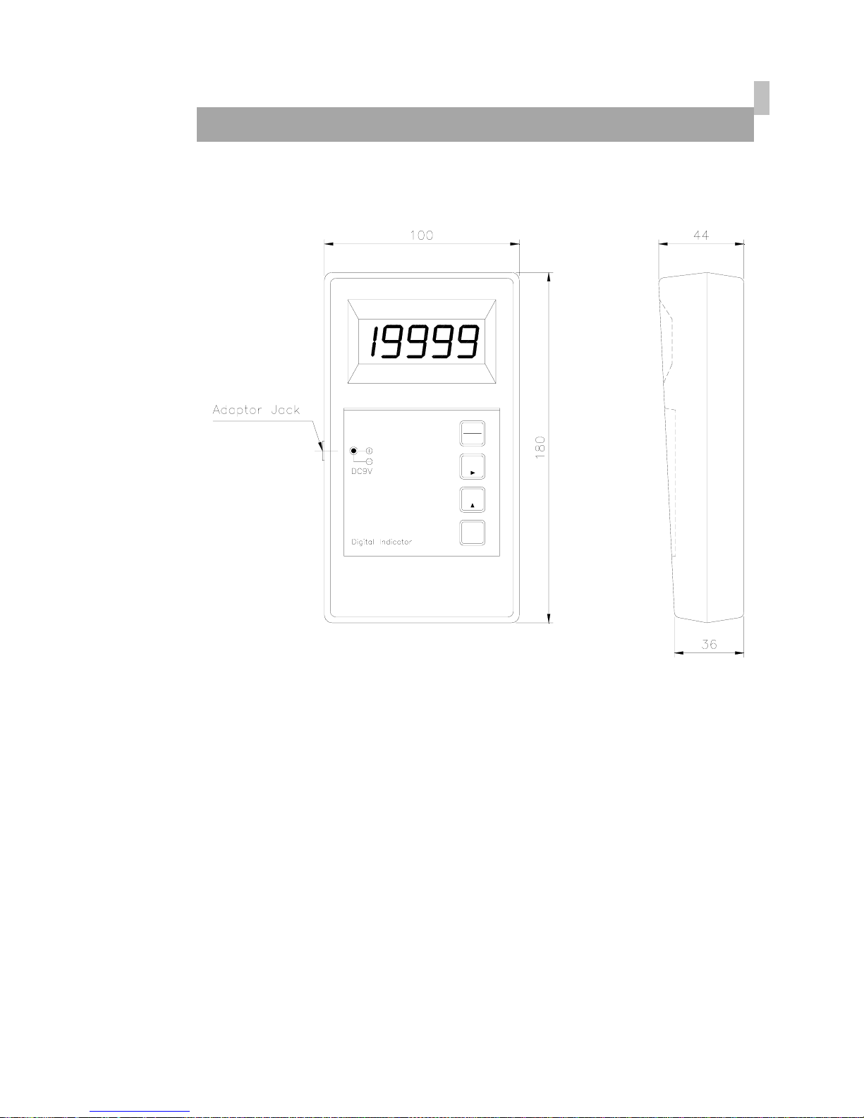
8=A9BG=CBG
BS-32
HOLD
ENT
ZERO
ON
OFF
6
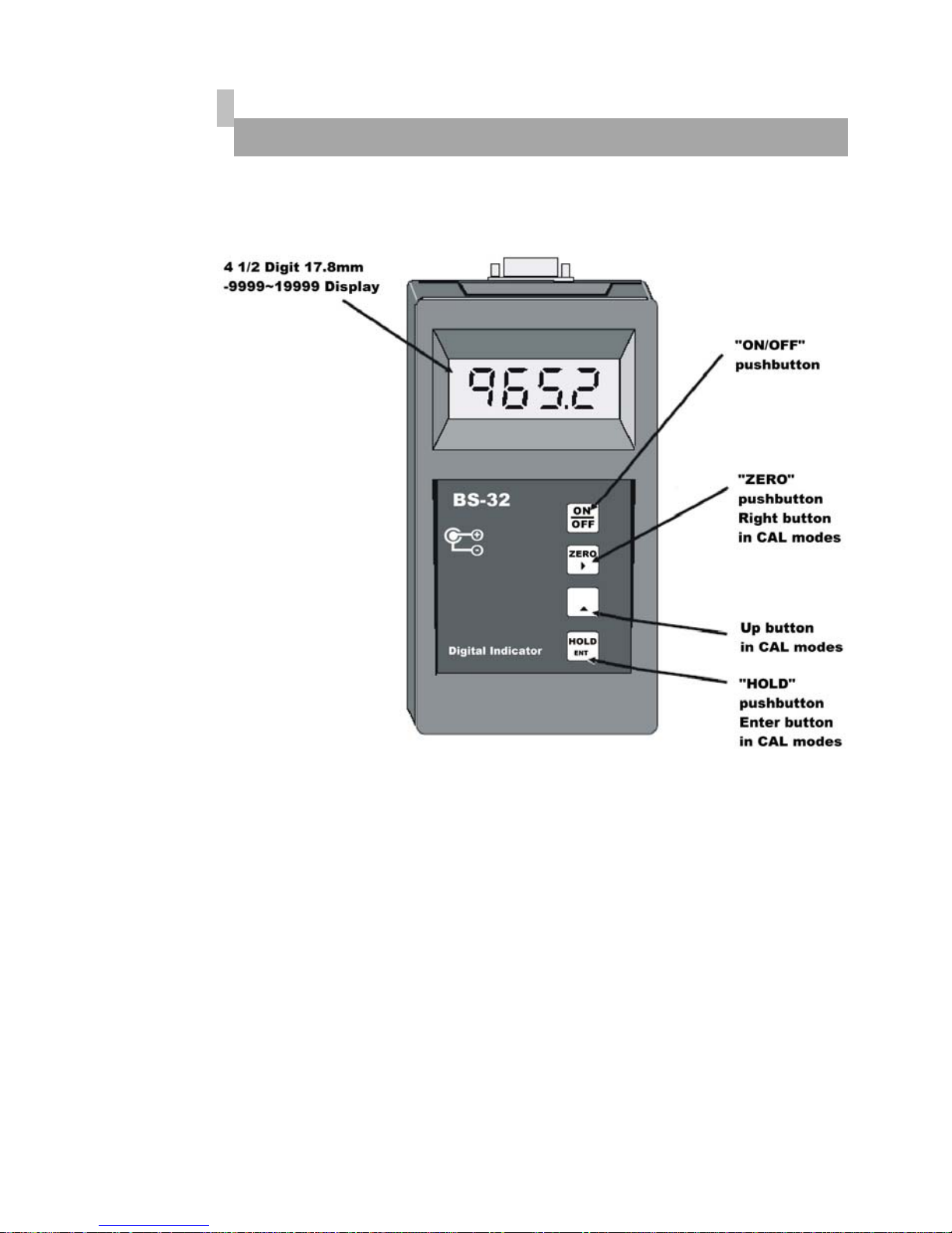
:fcbhDUbY`
7
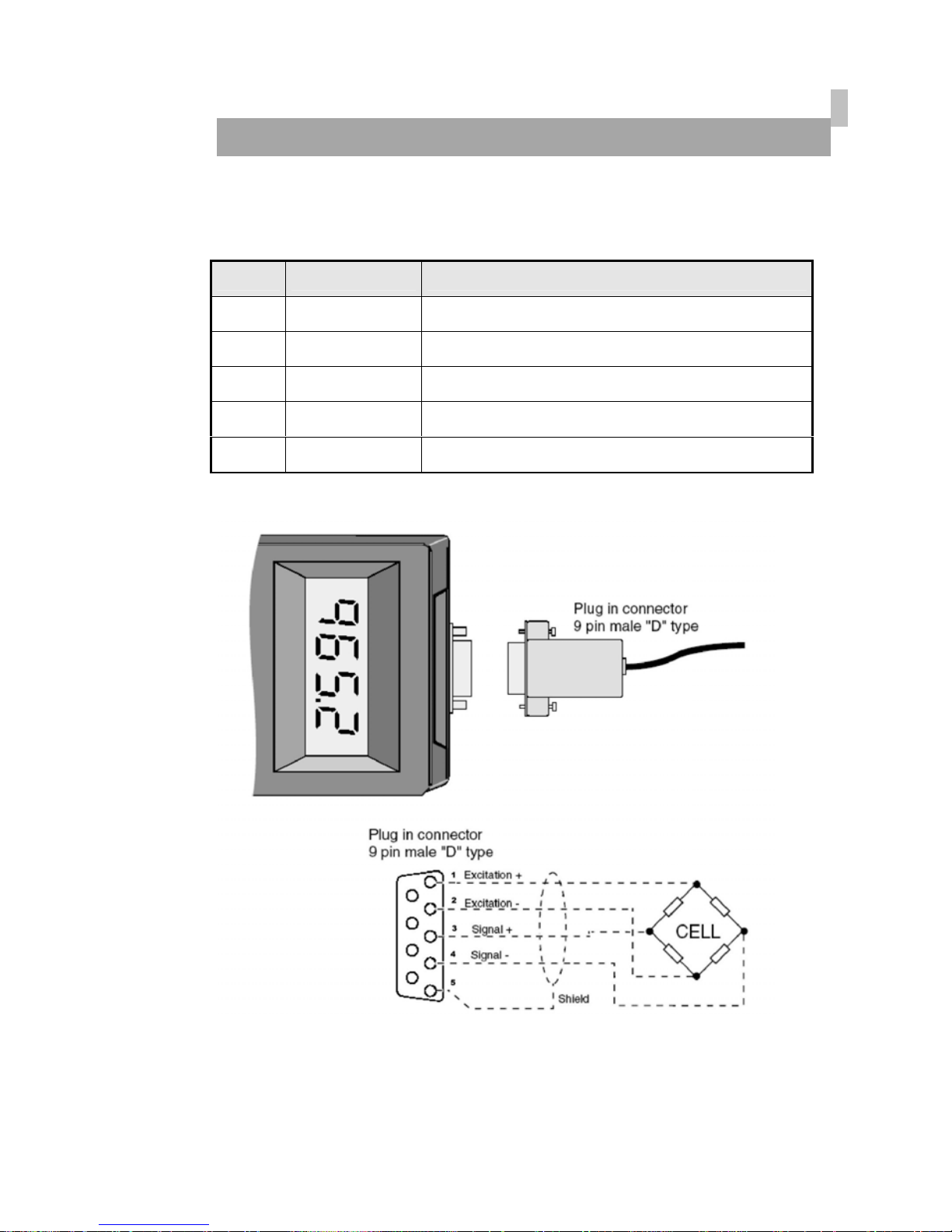
7CBB97H=CB
■ @C5879@@
■ 57585DH9F : Port for DC power. (DC 9V adapter are available)
■ FG!&'&7DCFH : Serial interface port. (computer, printer)
Pin no. SIGNAL
1 E+ Load cell Input Voltage (+) : EXC+ (red)
2 E- Load cell Input Voltage (-) : EXC- (white)
3 S+ Load cell output (+) : SIG+ (green)
4 S- Load cell output (-) : SIG- (blue)
5 FG SHIELD

8
65HH9FM IG5;9
%"6UhhYfm GdYW]Z]WUh]cb
MAKER : ROCKET
MODEL : ALKALINE BATTERY
LR6 (DC 1.5V) x 4 ea
&"@ck 6UhhYfm G][bU`
If you don
’
t charge the battery, after “Lo.bt” display.
Display is turned off 30 minutes later.

9
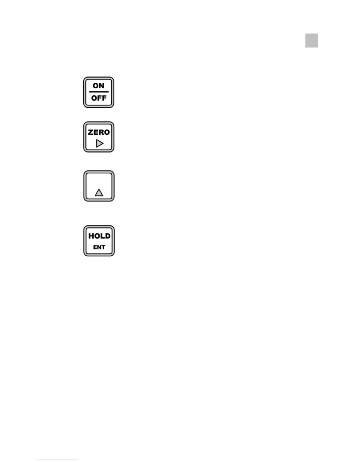
?9M6C5F8
■ CB#C::_Ym
Turn the scale ON, OFF toggle action.
■ Returns the display to 0
■ No used
■ Instant Hold : The instant display value can now be held
by pressing button.
10
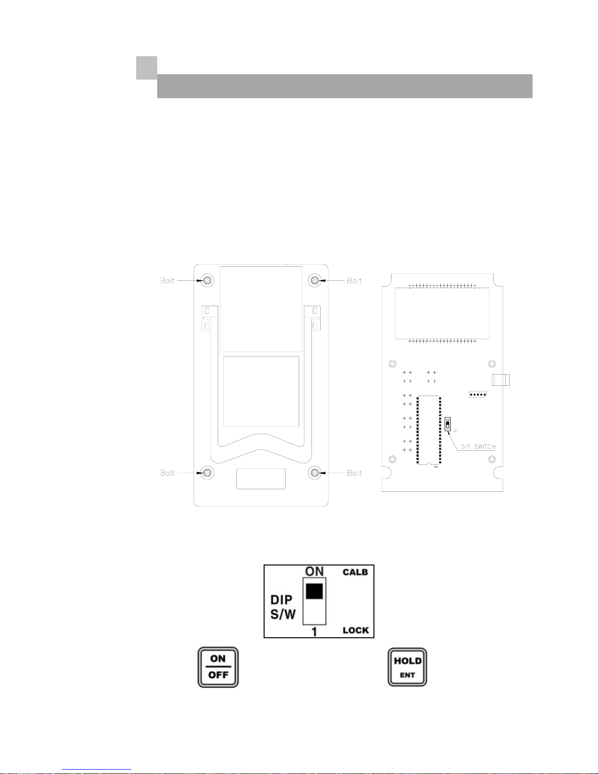
7U`]VfUh]cbacXY
%"<ckhcYbhYf75@acXY
The CAL can be enabled or disabled via a DIP switch J1 located at the
display end of the BS-32 circuit board.
To gain access to the DIP switch remove the four screws at the rear of
the BS-32 case and remove the back.
8]dg`]XYGK75@6"–75@=6F5H=CBAcXY
Pressing the key while pressing the key
and set mode start.
11
&"?Ym IgU[Y
■ 75@acXY : Switch to select one of the modes cycles.
■ 75@acXY :
Change the digit of the set value.
Move to the right by 1 place.
■ 75@acXY :
Available keys instead of numeric keys.
Change the set value
Increases the first place value to 1.
■ 75@acXY : Store current condition and exit.
12
'"7U`]VfUh]cbAYbiGhYd%rGhYd+
Step 1 : Minimum Division Set
Step 2 : Zero Calibration
Step 3 : Decimal Point Adjustment
Step 4 : Setting Weight in span calibration
Step 5 : Maximum Capacity Set
Step 6 : Overload Weight Set
Step 7 : END
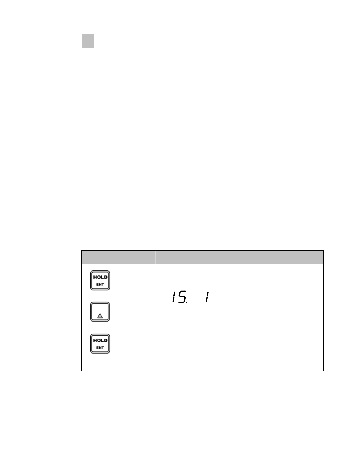
GhYd%
- Function : A]b]aia8]j]g]cbGYh
Range → 1, 2, 5, 10, 20, 50
A step to set up a division value.
"d" means "Division" and "xx" means a division capable of displaying.
Also this value will be displayed as 1-2-5-10-20-50 by each key.
A step to set up a Decimal point is Function mode.
So, it will be go to the next step recording the position.
Key Display Description
increase
Store and
move into
next menu
1 kg (Decimal point : 0)
1 : 1,2,3,4,5…
2 : 2,4,6,8,10…
5 : 5,10,15,20,25…
10 : 10,20,30,40,50…
20 : 20,40,60,80,100…
50 : 50,100,150,200,250…
☞ REF 1.The minimum division means the value of one division.
☞ REF 2. External resolution is obtained by division the min. division by the
maximum capacity. Set the resolution to be within 1/10,000.

13
GhYd&
- Function : NYfc7U`]VfUh]cb
Key Display Description
Zero calibration
and move into
next menu
Unload the tray and press “ENT”
key Under zero calibration
Zero calibration is completed.
☞ REF 1. If zero calibration is done without any error, “18888” message is
displayed and program moves into Step 3 automatically.
☞ REF 2. If the “ZERO” key is pressed, only zero calibration is completed
and program moves SAVE & EXIT mode. Turn s/w off.
GhYd'
- Function : 8YW]aU` Dc]bh 5X^ighaYbh
Key Display Description
: increase
: Store and
move into
next menu
18888 : 0
1888.8 : 0.0
188.88 : 0.00
18.888 : 0.000
1.8888 : 0.0000
14
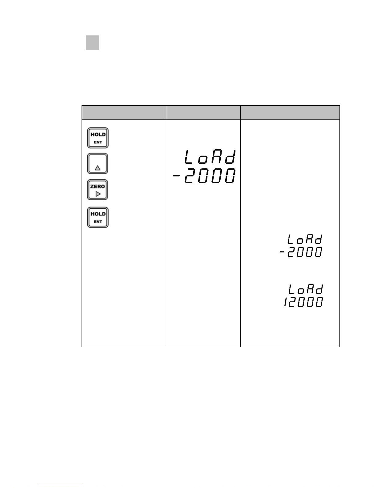
GhYd(
- Function : GYhh]b[KY][\h=bGdUb7U`]VfUh]cb
Range → 1~ 19,999kg
Key Display Description
: Increase
: Shift of digit
: Store and
move into
next menu
Setting Weight
2000kg
Load the weight which was
set in and press “ENT” key.
Under span calibration
Example : 2000kg setting
12000kg setting
☞ REF 1. The weight shall be within the range of 10%~100% of maximum
weight.
☞ REF 2. The setting weight must be over the range of 10% of maximum
weight.
☞ REF 3. The setting weight over the maximum capacity.

15
GhYd)
- Function : AUl]aia7UdUW]hmGYh
Range → 1 ~ 19,999kg
Key Display Description
: Increase
: Shift of digit
: Store and
move into
next menu
Maximum capacity
2000kg
☞ REF 1. The maximum capacity means the maximum weight that scale
can measure.
GhYd*
- Function : CjYf`cUX kY][\hGYh
Range → 1 ~ 19,999kg
Key Display Description
: Increase
: Shift of digit
: Store and
Move into
Next menu
Overload capacity
2200kg

16
GhYd+
- Function : 9B8
The "Good" message is displayed in 7 step,
all span adjustment is end.
Press “ENT” key after put down of span standard weight on the
platform.
The indicator will enter into user's weighing mode.
Key Display Description
: Store and
move into
weighing
mode
END
("<ckhcYbhYfKY][\]b[acXY
Slid switch usage
8]dg`]XYGK@C7?–KY][\]b[AcXY

17
GS
NT
UNIT
I
kg
US
ST
OL
GYf]U`=bhYfZUWYFG!&'&7
ઔ G][bU`:cfaUh
■ Type : EIA-RS-232C
■ Method : Full-Duplex , Asynchronous, Bi-direction
■ Baud rate : 2400bps ( Baud-Rate )
■ Format : ① Data Bit : 7
② Start/Stop : 1 bit
③ Parity Bit : 1 (Even)
④ Code : ASCII
■ Data Format
① Header 1
- US : WEIGHT UNSTABLE
- ST : WEIGHT STABLE
- OL : OVER LOAD
② Header 2
- GS : GROSS WEIGHT MODE
- NT : NET WEIGHT MODE
③ WEIGHT (8 byte)
- SIGNAL ( + or - )
- WEIGHT ( Included Decimal point )
- 100.0 kg : ‘0’ , ‘0’ , ‘0’ , ‘1’ , ‘0’ , ‘0’ , ‘.’ , ‘0’,
- 150.5 kg : ‘0’ , ‘0’ , ‘0’ , ‘1’ , ‘5’ , ‘0’ , ‘.’ , ‘5’,
- 165.3 kg : ‘-’ , ‘0’ , ‘0’ , ‘1’ , ‘6’ , ‘5’ , ‘.’ , ‘3’,
Each ASCII code of weight transmitted by 8 byte.( ‘0’ : 0 x 20)
④ Unit
- kg : Unit of kilogram
DATA (8byte)
CR
LF
,
,

18
ઔ FG!&'&7dcfhWcbbYWh]cb
○ 3 Transmit Data
○ 2 Receive Data
○ 5 Chassis Ground
○ 1 Carrier Detect
○ 4 Data Terminal Ready
○ 6 Data Set Ready
○ 7 Request to Send
○ 8 Clear to Send
TXD 1 ○
GND 2 ○
2 pin connector
RS-232C
p
ort of
BS-32
9 pin port(Female)
serial port of
computer

19
9ffcfAYggU[YUbXHfciV`YG\cch]b[
ERROR CAUSE A/S Reference.
Waving a weight
Value.
Appear "no.LC"
c Load cell damage
d Insulation
resistance
badness of load cell.
eWeighing part error
c Checking for Input,
Output of load cell.
Resistance Value.
d Checking Insulation
Resistance value of
Load cell.
c Input resistance
: about 1130Ω
dOutput resistance
: about 1000Ω
e Insulation
Resistance
: over100MΩ
c Load cell damage.
c Checking Insulation
Resistance value of
Load cell.
(Normal Max 100MΩ or
-OL-appear)
A. Changing a
Weight value,
B. Not return to
ZERO
Appear "Ovr "
(OVER LOAD) c Disconnected to
Load Cell.
c Confirm a connect of
Load cell
d Checking a single wire
Of load cell cable
Weight (-) changed
Appear "-Ovr "
(OVER LOAD)
c Load cell output
(SIG+,SIG-)changed. c Load cell connector
c Load cell damage
d Connection Error
c Load cell damage
d Load cell connector
Appear "Ovr" or
"-Ovr "
cExcess Max weight c Remove excess weight
Other Bongshin Touch Panel manuals


Popular Touch Panel manuals by other brands


Panasonic
Panasonic UT-MB5 Series INSTALLATION PROCEDURE

Viltrox
Viltrox DC-550 PRO user manual

Avalue Technology
Avalue Technology MPC-21W3 Quick reference guide

JETWAY
JETWAY HPC150R-DCP6305E Series user manual

OPTO-EDU
OPTO-EDU A59.3521 instruction manual

Gonnheimer Elektronic
Gonnheimer Elektronic D122.A Series user manual


