BEKA FOUNDATION BA614DF-F User manual

Issue: 2
23
rd
June 2011
BA614DF-F
FOUNDATION™ fieldbus
Field mounting
Fieldbus Indicator
Issue: 2

2
1. Description
1.1 Documentation
2. System Design
3. Installation
3.1 Location
3.2 Installation procedure
3.3 EMC
4. Maintenance
4.1 Fault finding during commissioning
4.2 Fault finding after commissioning
4.3 Servicing
4.4 Routine maintenance
4.5 Guarantee
4.6 Customer comments
5. Accessories
5.1 Scale and Tag marking
5.2 Tag plate
5.3 Pipe mounting kits
5.4 Fieldbus Interface Guide
CONTENTS
The BA614DF-F is CE marked to show compliance with the European EMC Directive 89/336/EEC

3
1. DESCRIPTION
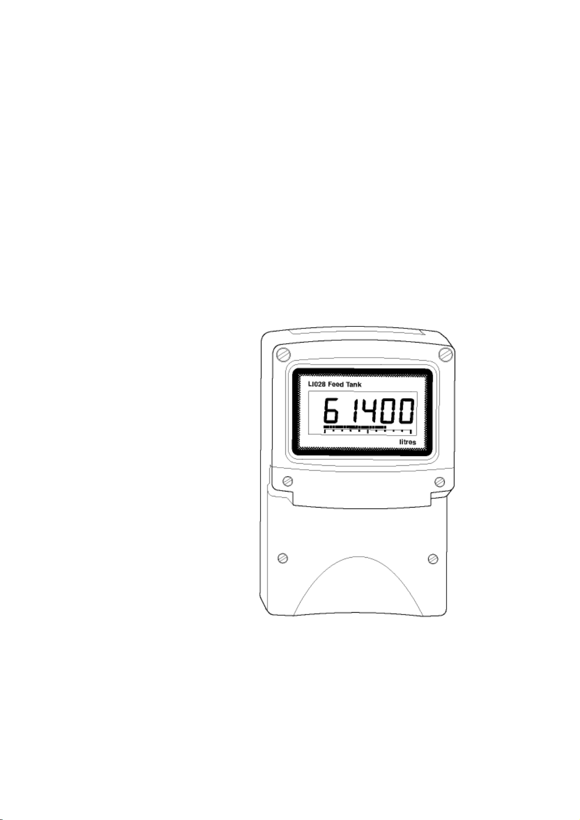
The BA614DF-F Fieldbus Indicator is a
FOUNDATION™ fieldbus instrument that can
display one fieldbus process variable on a five digit
LCD and 31 segment analogue bargraph. The
instrument is bus powered so no additional power
supply is required.
Communication Fieldbus Function
Protocol Block
FOUNDATION™ fieldbus Input Selector (1 x IS)
The Device Description files may be downloaded
from The Fieldbus Foundation or the BEKA
associates web site at www.beka.co.uk.
Housed in a robust IP66 glass reinforced polyester
(GRP) enclosure with a toughened glass window,
the BA614DF-F is surface mounting, or may be
pipe mounted using one of the accessory kits.
1.1 Documentation
This instruction manual describes system design
and installation of the BA614DF-F Fieldbus
Indicator. For commissioning information please
refer to:
FOUNDATION™ fieldbus
Fieldbus Interface Guide
for
Fieldbus Displays and
Fieldbus Indicators
which can be requested via the BEKA web site at
www.beka.co.uk
The instrument’s communication protocol is shown
on a label inside the terminal cover. The ‘-F’ order
code suffix also indicates the protocol but is not
shown on the instrument identification label.
2. SYSTEM DESIGN
The BA614DF-F Indicator is powered and
communicates via the fieldbus which is connected
to non-polarised terminals 1 and 2. As shown in
Fig 1 the instrument may be connected to any
fieldbus segment which can supply the additional
13mA required to power the instrument.
Fig 1 Fieldbus system
3. INSTALLATION
3.1 Location
The BA614DF-F Fieldbus Indicator is housed in a
robust IP66 glass reinforced polyester (GRP)
enclosure incorporating a toughened glass window
and stainless steel fittings. It is suitable for exterior
mounting in most industrial environments, including
offshore and wastewater treatment installations.
Please consult BEKA associates if high vibration is
anticipated.
The BA614DF-F enclosure is surface mounting.
Accessory kits described in sections 5.3 of this
manual enable the instrument to be mounted onto
a vertical or horizontal pipe.
The field terminals and the two enclosure mounting
holes are located in a separate compartment with a
sealed cover allowing the instrument to be installed
without exposing the display assembly.
The BA614DF-F earth terminal is connected to the
carbon loaded GRP enclosure. If this enclosure is
not bolted to an earthed post or structure, the earth
terminal should be connected to a local earth.
The BA614DF-F enclosure is supplied with a
bonding plate to ensure electrical continuity
between the three conduit / cable entries.

4
3.2 Installation Procedure
Fig 2 illustrates the instrument installation
procedure.
a. Remove the instrument terminal cover by
unscrewing the two captive 'A' screws.
b. Mount the instrument on a flat surface and
secure with two M6 screws through the 'B'
holes. Alternatively use one of the mounting
kits described in section 5.3
c. Remove the temporary dust seals from the
three cable entries and install the required
glands, conduit fittings or blanking plugs.
Note: The temporary dust seals fitted for
transit do not maintain the IP66 protection of
the BA614DF-F enclosure.
d. Connect the field wiring to the terminals as
shown in Fig 3.
e. Replace the instrument terminal cover and
evenly tighten the two 'A' screws.
Fig 2 BA614DF-F installation procedure
3.3 EMC
The BA614DF-F complies with the requirements of
the European EMC Directive 89/336/EEC. For
specified immunity, all wiring should be in
screened twisted pairs with the screens earthed at
one point.
Fig 3 Dimensions and terminal connections

5
4. MAINTENANCE
4.1 Fault finding during commissioning
If a BA614DF-F fails to function during
commissioning the following procedure should be
followed:
Symptom Cause Check:
No Display Instrument not
correctly
connected or
powered.
9 to 32V between
terminals 1 & 2.
Display shows
‘9.9.9.9.9’ with all
decimal points
flashing; all
bargraph
segments
activated and
bargraph scale
flashing.
Value
over-range Variable source
Decimal point
configuration.
Display shows
‘-9.9.9.9.9’ with
all decimal points
flashing; no
bargraph
segments
activated and
bargraph scale
flashing.
Value
under-range Variable source
Decimal point
configuration
Display
alternates
between value
and the word
‘bAd’. Bargraph
flashes.
Status of fieldbus
variable has a
quality of ‘BAD’
or a fault state is
active.
Display has not
yet received
data.
Variable source
Fieldbus
configuration.
Bargraph scale
flashes. Variable is
outside the limits
defined for the
bargraph.
Bargraph
configuration.
All display
segments
activated.
Display is
initialising. This is normal
operation, after a
few seconds the
firmware version
will be displayed
prior to entering
the operational
mode.
4.2 Fault finding after commissioning
ENSURE PLANT SAFETY BEFORE
STARTING MAINTENANCE
If a BA614DF-F fails after it has been functioning
correctly, the table shown in section 4.1 may help
to identify the cause of the failure.
If this procedure does not reveal the cause of the
fault, it is recommended that the instrument is
replaced.
4.3 Servicing
We recommend that faulty BA614DF-F Fieldbus
Indicators are returned to BEKA associates or to
our local agent for repair.
4.4 Routine maintenance
The mechanical and electrical condition of the
instrument should be regularly checked. Initially
annual inspections are recommended, but the
inspection frequency should be adjusted to suit the
environmental conditions.
4.5 Guarantee
Instruments which fail within the guarantee period
should be returned to BEKA associates or our local
agent. It is helpful if a brief description of the fault
symptoms is provided.
4.6 Customer comments
BEKA associates is always pleased to receive
comments from customers about our products and
services. All communications are acknowledged
and whenever possible, suggestions are
implemented.

6
5. ACCESSORIES
5.1 Scale and tag marking
BA614DF-F indicators are fitted with a blank
escutcheon around the liquid crystal display. If
specified when the instrument is ordered, this can
be supplied printed with units of measurement and
tag information. Alternatively, information may be
added on-site via an embossed strip, dry transfer
or a permanent marker.
To gain access to the display escutcheon remove
the terminal cover by unscrewing the two 'A'
screws which will reveal two concealed 'D' screws.
Unscrew all four 'D' screws and carefully lift off the
front of the instrument. The location of all these
screws is shown in Fig 2.
After adding the required legends, or fitting a new
pre-printed self-adhesive escutcheon, ensure that
the gasket is correctly positioned before
reassembling the instrument enclosure.
5.2 Tag plate
The BA614DF-F can be supplied with a blank or
custom laser marked stainless steel plate secured
by two screws to the front of the instrument
enclosure. This plate can accommodate:
1 row of 9 alphanumeric characters 10mm high
or 1 row of 11 alphanumeric characters 7mm high
or 2 rows of 18 alphanumeric characters 5mm
high
5.3 Pipe mounting kits
Two pipe mounting kits are available for securing
the BA614DF-F to a horizontal or vertical pipe.
BA392D Stainless steel bracket secured by two
worm drive hose clips for 60 to 80mm
outside diameter pipes.
BA393 Heavy-duty stainless steel bracket
secured by a single 'V' bolt. Will clamp
to any pipe with an outside diameter
between 40 and 80mm.
5.4 Fieldbus Interface Guide
The FOUNDATION™ fieldbus Interface Guide for
Fieldbus Displays & Fieldbus Indicators contains
commissioning information for the BA614DF. A
copy may be requested from the BEKA sales office
or from the BEKA web site at www.beka.co.uk
Table of contents
Other BEKA Touch Panel manuals
Popular Touch Panel manuals by other brands

Harman
Harman RMBK-1001 instruction manual

Winmate
Winmate R10IB3S-67T2 Quick start guides

DMP Electronics
DMP Electronics 7860 installation guide

Cincoze
Cincoze CV-100/P2102 Series user manual

Extron electronics
Extron electronics TouchLink TLP Pro 1020 Series user guide

WIKA
WIKA A-IAI-1 operating instructions