BONMET SDL10A User manual

User Manual
For SD Series
Smart & Accurate

1
BONMET motion GmbH/www.bonmet.com/www.bonmet.de
Preface
Thank you for choosing BONMET‘s DC servo products.
This manual is a user guide that provides the information on how to install, operate and maintain
SD series DC servo drive. The contents of this manual include the following topics:
●Installation of DC servo drives and motors
●Configuration and wiring
●Trial run steps
●Control functions and adjusting methods of DC servo drives
●Parameter settings
●Inspection and maintenance
●Troubleshooting
●Application examples
Before using the product, please read this manual to ensure correct use. Users should thoroughly
understand all safety precautions (DANGERS and WARNINGS) before proceeding with the
installation, wiring and operation. If you still have any problem, please contact with the local
Bonmet sales representative. Place this user manual in a safe location for future reference.

2
BONMET motion GmbH/www.bonmet.com/www.bonmet.de
Safety Precautions
●To prevent electric shock, note the following:
DANGEROUS
·Before wiring or inspection, switch power off and wait for more than 10 minutes. Then,
confirm the voltage is safe with voltage tester. Otherwise, you may get an electric shock.
·Wiring must be carried by electrical engineer.
·Connect the servo drive and servo motor to ground.
·Operate the switches with dry hand to prevent an electric shock.
·The cables should not be damaged, stressed, loaded, or pinched. Otherwise, you may get an
electric shock.
●To prevent fire, note the following:
CAUTION
·Do not install the servo drive, servo motor and regenerative brake resistor on or near
combustibles. Otherwise a fire may cause.
·When the servo drive has become faulty, switch off the main power. Continuous flow of a
large current may cause a fire.
·When there is a signal faulty as a regenerative brake resistor is used, please switch the main
power off. Otherwise, a regenerative brake transistor fault may overheat the regenerative
brake resistor and cause a fire.
●Wiring Precautions
CAUTION
·Wire the equipment correctly and securely.
·Connect the output terminals (U, V, W) correctly.
·Do not connect AC power directly to the servo motor or servo drive.
●Operation and Adjustment Precautions
CAUTION
·Do not touch the radiator and the regenerative brake resistor as they are overheated.
·Do not set parameter value unduly. If so, system would be instable.
·Do not touch the rotating parts of the servo motor in operation. Doing so may cause injury.
●Others
CAUTION
·Do not attempt to remold the servo drive.

3
BONMET motion GmbH/www.bonmet.com/www.bonmet.de
CONTENTS
Chapter 1
• • • • • •
Model and Specifications
Chapter 2
• • • • • •
Installation
Chapter 3
• • • • • •
Wiring
Chapter 4
• • • • • •
Display and Operation
Chapter 5
• • • • • •
Operation
Chapter 6
• • • • • •
Parameters
Chapter 7
• • • • • •
Communication
Chapter 8
• • • • • •
Protective Functions

4
BONMET motion GmbH/www.bonmet.com/www.bonmet.de
Chapter 1 Model and Specifications
1.1 Unpacking Check
After receiving the DC servo drive, please check for the followings in order to prevent mistake during purchase or
shipment:
●Check the following section about the model explanation of the servo drive and motor to ensure that the
product is what you have ordered.
●Rotate the motor shaft slightly by hand, a smooth rotation will indicate a good motor. However, a servo
motor with holding brake can not be rotated manually unless give power to the holding brake to release
the shaft.
●Inspect the unit to insure it was not damaged during shipment.
If any items are damaged or incorrect, please inform the distributor whom you purchased the product from or your
local BONMET sales representative.
1.2 Model Explanation
●Nameplate Explanation
Figure 1-1 Nameplate explanation
●Model Explanation
SD
L
10
A
XX
1
2
3
4
5
1.Product type: S(SD)- Series DC servo drive;
2.Power supply:48~80VDC
3.Nominal current:10A
4.Type code;
5.Software customized logo.
1.3 Product Features
●Definition of The Motor Rotation Direction
Positive direction(CCW)
Negative direction(CW)
Definition of the motor rotation direction:facing the motor shaft side, CCW (counterclockwise) direction is
positive direction, CW (clockwise) direction is negative direction.
Model
Input Power
Nominal Output
Serial Number
5
BONMET motion GmbH/www.bonmet.com/www.bonmet.de
Model
SDL10A
SDL10B
Input Power Supply
DC 24V~85V
Environment
Temperature
Operation:0~40℃Storage:-40℃~50℃
Ambient Humidity
40%~80%( non-condensation)
Atmospheric Pressure
86~106kPa
Control Method
MOSFET
Control Mode
①Position control ②Speed control ③Torque control
Regeneration Brake
None
Speed
Characteristics
Speed Frequency
Response
300Hz or more
Speed Fluctuation Rate
±0.03 or less (Load 0~100%); ±0.02 or less (Power supply -15~+10%)
(Value corresponds to the nominal speed)
Speed Ratio
1:5000
Input Signal
Status Input Signal
Servo enable、Alarm clear
Command Input Signal
Analog torque / speed command input terminals、Pulse command input terminal
Output Signal
Status Output Signal
Servo alarm、Position complete output / speed reach output
Position Output Signal
Differential output for A、B、Z pulse, Open collector output for Z pulse
Position
Control
Maximum Input Pulse
Frequency
500KHz
Input mode
①Differential output ②Open collector output
Command mode
①Command/direction pulse ②CCW/CW pulse ③A/B pulse (set by parameters)
Command Smoothing
Method
Position command filter
Electronic Gear
1~30000/1~300000(Recommended value:50~1/50)
Torque Limit
①Set by parameters(CCW/CW)②16 speed command set by parameters
③Controlled by analog command
Speed
Control
Comma
nd mode
Internal
Command
16 speed command set by parameters,
Analog
Command
0~±10VDC(Default:10VDC corresponds 3000rpm)
Pulse
Command
0~500KHz(Default:500KHz corresponds 3000rpm)
Command Smoothing
①Analog low-pass filter order ②Increase / Decrease time constant ③Position
command filter
Speed Limit
Set by parameters
Torque
Control
Command mode
0~±10VDC(Default:10VDC corresponds 100% nominal torque)
Command Smoothing
Torque command filter
Speed Limit
Set by parameters
Torque Limit
Set by parameters(CCW/CW)
Communication
RS-232 port、RS-485 port
Bus Control Function
Mod bus
Monitoring Function
The percentage of motor torque, ,Motor speed, Motor accumulated travel pulse,
Torque command value, Speed command value,Accumulative command pulse,
Single-phase current, Absolute position of rotor, Position deviation pulse, Alarm
code, Input and output terminal signal status, etc.
Protective Function
Encoder signal abnormalities, Overload, Over current, Speed tolerance, Over
location etc.
Applicable Load Inertia
Less than five times of motor inertia
6
BONMET motion GmbH/www.bonmet.com/www.bonmet.de
Chapter 2 Installation
2.1 Notes for Installation
●Do not bend or strain the cables between servo drive and motor;
●When mounting the servo drive and servo motor, make sure to tighten all screws to secure the machine
in place;
●Motor shaft must be concentric with the axis of transmission;
●If the cable between drive and motor is longer than 10 meters, the cable must be thicken.
2.2 Installation Environment
●Please install the servo system in the place without oil mist, dust or electrical control cabinet (ensure the
temperature below 50℃, relative humidity below 80%. The long-term safety temperature below 40℃)
●Please install the servo system in the place without radioactive matters and combustibles.
●Take an anti-vibration measure to guarantee that the servo drive is free from vibration impact, ensuring
the vibration under 0.5G (4.9m/s2).
●Please install the servo system in the place without direct sunlight.
●Interferential equipment nearby would take great effects to the power wire and control wire which will
cause miss operation. For normal operation, a noise filter or any other anti-jamming measures is
necessary to be carried out. Leakage current would increase after installing a noise filter, therefore an
isolation transformer can be used to avoid this problem. Possessing a reasonable alignment and inhibit
measures is very important because the control signal wire is easy to be interfered.
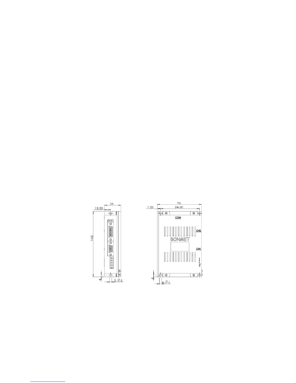
2.3 Dimensions(Unit: mm)
Figure 2-1 Dimension drawings
2.4 Installation Direction and Space
●The equipment must be installed in the specified direction. Otherwise, a fault may occur.
●Leave specified clearances between the servo drive and control box inside walls or other equipment.
●Leave a large clearance between the top of the servo drive and the internal surface of the control box,
and install a fan to prevent the internal temperature of the control box from exceeding the environmental

7
BONMET motion GmbH/www.bonmet.com/www.bonmet.de
conditions.
●When using heat generating equipment such as the regenerative brake option, install them with full
consideration of heat generation so that the servo drive is not affected. Install the servo drive on a
perpendicular wall in the correct vertical direction.
Figure 2-2 installation schematic diagram for drives
Chapter 3 Wiring
2.5 Connections
3.1.1 Note
●All terminals and plugs must be screwed well, poor contact or disconnection could lead to accidents.
●In order to prevent error movement caused by noise, please install isolation transformers and noise filter.
●The equipment must be grounded.
●Do not put power lines and signal lines in a same conduit or their binding them together, the distance between
power lines and signal lines should be 30cm at least, otherwise it may cause interference.
●Please use the shielded twisted wire as signal cable.
●Do not switch power supply frequently. The maximum frequency should be no more than once per minute.
2.6 Connection
Control
Card
Power
48~80VDC Motor
Controler
≥
25
mm
≥
25
mm
≥
100
mm
≥
100
mm
Air flow
Air flow
≥
100
mm

8
BONMET motion GmbH/www.bonmet.com/www.bonmet.de
2.7 Terminals
Terminal
Name
Function
+VDC、GND
Drive power terminal
Connect with 48~80VDC
U、V、W
Motor terminal
Connect with motor
CN1
Encoder Connector
Connect with encoder
CN2
I/O Connector
I/O port
COM
Communication Connector
Connect with PC or controller
2.8 Power Terminal
number
Name
Symbol
Description
1
Ground
GND
Connect with OV
2
Power
+VDC
Connect with 48~80V
3
Motor U、V、W terminal
U
Connect with motor power terminal
4
V
5
W
2.9 Encoder Connector CN1
Terminal
number
Name
Function
Symbol
I/O
Description
1
Power supply(5V)
+5V
The power supply and public ground of encoder. It is
necessary to use a parallel multi-cored wire to reduce
the pressure drop of wires.
13
Public ground
0V
7
Encoder CSL input
CSL
Type7
Connect with the electro-optic encoder CSL.
2
Encoder CSH input
CSH
Connect with the electro-optic encoder CSH.
6
Encoder CLKL input
CLKL
Type7
Connect with the electro-optic encoder CLKL.
1
Encoder CLKH input
CLKH
Connect with the electro-optic encoder CLKH.
8
Encoder DOL input
DOL
Type7
Connect with the electro-optic encoder DOL.
3
Encoder DOH input
DOH
Connect with the electro-optic encoder DOH.
4
Encoder A+ input
A+
Type7
Connect with the electro-optic encoder A+.
9
Encoder A- input
A-
Connect with the electro-optic encoder A-.
5
Encoder B+ input
B+
Type7
Connect with the electro-optic encoder B+.
10
Encoder B- input
B-
Connect with the electro-optic encoder B-.
14
Encoder Z+ input
Z+
Type7
Connect with the electro-optic encoder Z+.
15
Encoder Z- input
Z-
Connect with the electro-optic encoder Z-.
2.10 I/O Connector CN2
12345
1
2
3
45
10
11
12
13
1415
6
7
8
9
26 20
21
22
2324
25
1
2
3
45
19
6
78
9
17 1618 11
12
13
1415 10
9
BONMET motion GmbH/www.bonmet.com/www.bonmet.de
Control mode: Pstands for position control, Sstands for speed control, Tstands for torque control.
Terminal
number
Name
Terminal symbol
Function
Symbol
I/O
mode
20
Servo enable
ServoEn+
Type1
Servo enable input terminal.
ServoEn ON: Operation enabled;
ServoEn OFF: Operation disabled.
[Note 1]: Make sure the servo motor is quiescent before
―ServoEn OFF‖ turns to ―ServoEn ON‖
[Note 2]: Please wait for 50 ms before inputting any
command in the State of ―ServoEn ON‖.
19
ServoEn-
3
Alarm clear
AlarmClr+
Type1
Alarm clear input terminal.
AlarmClr ON: Clear the system alarm;
AlarmClr OFF: Maintain the system alarm.
[Note]: As the alarm code is less than 12, please cut off
the power supply and repair the drive.
12
AlarmClr-
5
Servo alarm
output
Alarm+
Type2
Output terminal of servo alarm.
ALM ON: Servo alarm output ON as there is no alarm;
ALM OFF: Servo alarm output OFF as there is any
alarm.
14
Alarm-
2
Command pulse
PLUS input
PulseInv+
Type3
P
External command pulse input terminal.
Note: pulse type is selected by parameter PN52.
①PN52=0, command pulse+ signal mode(default state);
②PN52=1, CCW/CW command pulse mode;
③PN52=2, 2-phase command pulse mode.
11
PulseInv-
1
Command pulse
SIGN input
SignInv+
Type3
P
10
SignInv-
24
Analog command
input
ASPEED+/
ATORQUE+
Type4
S、T
Command input terminal for external analog
torque/speed (difference mode), the impedance is 10kΩ,
the voltage is -10V~+10V.
25
ASPEED-/
ATORQUE-
26
Analog ground
AGND
The grounding line of analog input.
7
Encoder
Phase-A signal
PhaseA+
Type5
1. Encoder signal A, B, Z for difference drive output
(output through 26LS31, corresponding to RS422 );
2. Non-isolative output (non-insulation).
16
PhaseA-
8
Encoder
phase-B signal
PhaseB+
Type5
17
PhaseB-
9
Encoder phase- Z
signal
PhaseZ+
Type5
18
PhaseZ-
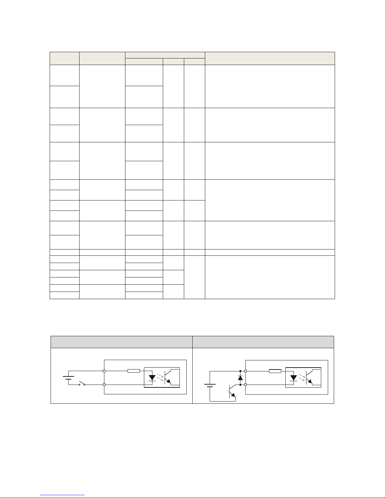
3.6.1 Wiring of Digital Input
Wiring of the relay circuit
Wiring of the open collector circuit
(1) Connect to contacts of switches and relays, or open collector output transistors.
(2) The power is provided by the user as the voltage range is DC12~24V and the current is more than 100mA.
Note: the internal circuit will be damaged if the power polarity is wrongly connected.
4.7K
VCCOM
ServoEn,etc
DC 12~24V
Servo drive
4.7K
VCCOM
ServoEn,etc
DC 12~24V
Servo drive

10
BONMET motion GmbH/www.bonmet.com/www.bonmet.de
3.6.2 Wiring of Digital Output
Wiring of the relay circuit
Wiring of the Optocoupler circuit
Note: it is possible to connect a freewheeling diode in the wiring of relay circuit.
(1) The output circuit is composed of open collector transistor outputs in the Darlington connection, and connect
to relays or photo-couplers.
(2) The power is provided by the user as the voltage range is DC5 ~ 24V and the current is more than 50mA.
Note: the internal circuit will be damaged if the power polarity is wrongly connected.
(3) As driving the inductive load such as relay, you must connect a freewheeling diode in parallel.
Note: It would damage the serve drive as if the freewheeling is wrongly connected.
(4) There exists collector to emitter voltage, VCE (SAT) of approx. 1V at transistor-ON, due to the Darlington
connection of the output or. Note that normal TTL IC cannot be directly connected since it does not meet
VIL.
3.6.3 Wiring of Pulse Input
There are two kinds of pulse inputs, line drive input and open-collector input. The max. input pulse frequency is
500kpps.
BONMET servo drive support three kind of pulse mode (Set by Pn-52): ①Pulse + Direction; ②CW+CCW pulse;
③A/B phase pulse
●Line drive input
●Open-collector input
There are two kind of open-collector input: NPN type (like Mitsubishi, Omron, Panasonic) and PNP type (like
Siemens). The wiring of open-collector as below:
Wiring of NPN type pulse input
Wiring of PNP type pulse input
⑴Check the pulse input kind and make the wiring according to the drawing, otherwise it may cause the damage.
DC 12~24V
Servo drive
Relay
50mA as MAX.
output
Host controller Servo drive
PULS+
PULS-
SIGN+
SIGN-
Servo drive
PULS+
PULS-
SIGN+
SIGN-
Host controller
R
R
VCC
Servo drive
PULS+
PULS-
SIGN+
SIGN-
Host controller
R
R
VCC

11
BONMET motion GmbH/www.bonmet.com/www.bonmet.de
⑵The Optocoupler supports max. to 15mA current. We need to add a current-limiting resistance as using
open-collector input.
Voltage of open-collector input
Value of current-limiting resistance
5V
Not need
12V
400
24V
1k
⑶The cable of pulse input should be twisted-paired and shielded to prevent from signal interference caused by
noise.
⑷The max. input pulse frequency is 500kpps, the relationship between pulse frequency and speed is a
proportional relationship as 500 kHz corresponds to 3000rpm.
Parameters
Differential drive input
Single-ended drive input
tck
>2μS
>5μS
th
>1μS
>2.5μS
tl
>1μS
>2.5μS
trh
<0.2μS
<0.3μS
trl
<0.2μS
<0.3μS
ts
>1μS
>2.5μS
tqck
>8μS
>10μS
tqh
>4μS
>5μS
tql
>4μS
>5μS
tqrh
<0.2μS
<0.3μS
tqrl
<0.2μS
<0.3μS
tqs
>1μS
>2.5μS
Sequence chart for pulse + direction
Sequence chart for CW+CCW pulse

12
BONMET motion GmbH/www.bonmet.com/www.bonmet.de
Sequence chart for A/B phase pulse
3.6.4 Wiring of Analog Input
Analog voltage input
Potentiometer input
Note:"AO" means analog command.
(1) AGND must be connected to the ground (0V) of analog command;
(2) Max. permissible input voltage to each input is ±10V;
(3) It is suggested that using Shielded twisted pair as the analog input cable;
(4) Analog input drift is normal, you can use analog input drift compensation function to deal with it..
3.6.5 Wiring of Encoder Differential Output
Wiring of line receiver
Wiring of optocoupler
(1) Feeds out the divided encoder outputs (A, B and Z-phase) in differential through each line driver.
(2) Customer can use a line receiver (like AM26LV32). Install a terminal resistor (approx. 330Ω) between line
receiver inputs without fail. And connect ―EGND‖ to the ground (0V) of the receiver.
(3) Customer can use a optocoupler to receive the signals.
(4) These outputs are not insulated.
3.4
Servo drive
AO+
AO-
Host controler
+
-
+
-
AGND
10KΩ
AO+
AO-
Adjust voltage
by potentiometer
+
-
AGND
10KΩ
2KΩ(1/2W)
200Ω(1/2W)
200Ω(1/2W)
10V
10V
Servo drive
Servo drive
PhaseA+
PhaseA-
PhaseB+
PhaseB-
Host controler
PhaseZ+
PhaseZ-
Pin_1
Pin_2
Pin_3
Pin_4
Pin_5
Pin_6
R
EGNDPin_9
AM26LS31
AM26LV32 or other line receiver
R
R
Servo drive
PhaseA+
PhaseA-
PhaseB+
PhaseB-
Host controler
PhaseZ+
PhaseZ-
Pin_1
Pin_2
Pin_3
Pin_4
Pin_5
Pin_6
220Ω(1/2W)
220Ω(1/2W)
220Ω(1/2W)
EGNDPin_9
AM26LS31
Optocoupler
13
BONMET motion GmbH/www.bonmet.com/www.bonmet.de
3.5 Communication Connector(CN3)
Serial-line terminal plug CN3
■RS-232
Termina
l
number
Name
Function
Symbol
Description
3
Receive data
RXD
Receive data signal.
5
Transmit data
TXD
Transmit data signal.
1
GND
GND
Inhibit signal earth.
■RS-485
Termina
l
number
Name
Function
Symbol
Description
7
Difference signal Data+
Data+
Data+ terminal
4
Difference signal Data-
Data-
Data- terminal
8
GND
GND
Inhibit signal earth.
Chapter 4 Operation
4.1 Operation steps
Item
Content
Reference
Installation
Please keep the motor shaft in a non-connection state, do not connect the motor
with mechanical system for servo action confirmation at first.
Chapter 2
↓
Wiring
Connect servo drive with power and peripheral device
Chapter 3
↓
Preparation before
operation
Please confirm all the necessary items before turn on the power. And check if
there is any alarm.
Chapter 4
↓
Action confirmation
Operate in speed mode to test the servo drive and servo motor without any load
on the shaft.
Chapter 4
↓
Parameters settings
Set parameters according to terms of use.
Chapter 5
↓
Trial operation
Connect motor with mechanical systems, turn on the power, and check whether
protective functions (such as emergency stop and stroke limit) are working.
Check operation at both low speed and high speed.
—
31 2
4 5 6
78
14
BONMET motion GmbH/www.bonmet.com/www.bonmet.de
↓
Gain adjustment
Adjust the gain to get a good performance.
Chapter 4
↓
Normal operation
You can carry out normal operation now. If any faulty happens, please refer to
"Chapter 7 Protection."
Chapter 7
Preparing For Operation
Turning Power ON and Checking Indicators
■Checking Power Supply Voltage
·Check to be sure that the power supply voltage is 24~85VDC
■Checking Terminal Block Wiring
·The power supply inputs (+VDC、GND)must be properly connected to the terminal block.
·The servo motor‘s power line(U、V、W)must be properly connected to the terminal block.
■Checking the servo motor
·The Encoder Cable must be securely connected to the Encoder Connector at the motor side.
·The power lines at the servo motor must be securely connected.
■Checking the Control Connectors
·The Control Cable must be securely connected to the I/O Control Connector (CN2).。
·The ServoEn command must be OFF.
4.2 Software(Servofly)operation instructions
4.2.1 Communication
⑴Connect servo drive with PC through serial cable.
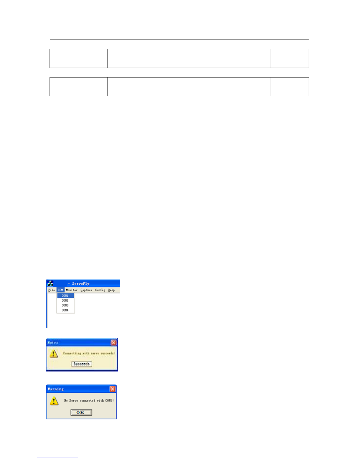
⑵Click “Servofly.exe‖and select the COM menu,click the defined COM port(can be modified by PC).
⑶The communication succeeds as the following dialog appears.
⑷The communication fails as the following dialog appears, please check the wiring.
15
BONMET motion GmbH/www.bonmet.com/www.bonmet.de
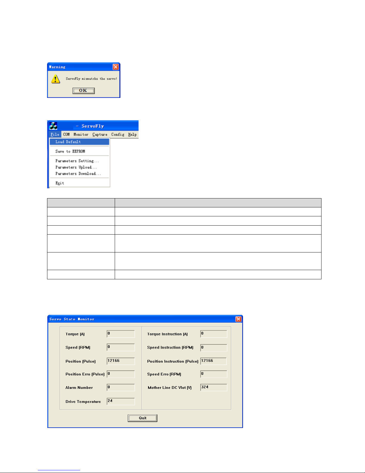
⑸The communication fails as the following dialog appears, it indicates that the software version does not match,
please select Pn-0 to check the version information, and download the right software on our website.
4.2.2 Basic function
1. Customers can use the basic function of the software in the ―File‖menu.
2. Function
Item
Function
Load Default
Restore default parameters(equal with ―EE-Def‖ in panel operation)
Save to EEPROM
Save the current parameters to EEPROM
Parameters Setting…
Parameter setting
Parameters Upload…
Upload the parameters from servo drive to PC ( please name the parameter file as
“xx.par”, otherwise the operation would be invalid)
Parameters Download…
Download the parameters from PC to servo drive(please DO NOT use this
function.)
Exit
Exit the software
4.2.3 Monitoring function
1. Monitoring the servo state
⑴―Servo State‖ choice under the ―Monitor‖ menu is the monitoring choice of the servo state.

16
BONMET motion GmbH/www.bonmet.com/www.bonmet.de
⑵Function
Item
Function
Torque(A)
Motor Q axis current(the value divided by 1.414 is motor current)
Torque Instruction(A)
Motor Q axis current command (the value divided by 1.414 is motor current
command)
Speed(RPM)
Motor speed(this is a real time value )
Speed Instruction(RPM)
Speed command
Position(Pulse)
Feedback pulse
Posiotn Instruction(Pulse)
Pulse command
Position Erro(Pulse)
Position deviation (pulse command minus feedback pulse)
Speed Erro(Pulse)
Speed deviation(this is a real time value)
Alarm Number
Alarm code(―0‖ means no alarm)
Mother Line DC Vlot(V)
Mother line DC voltage
Drive Temperature
The temperature of the heat sink inside part
②Physical port status monitoring function
⑴The ―Physical State‖ item under the ―Monitor‖ menu is for the physical port status monitoring function.
17
BONMET motion GmbH/www.bonmet.com/www.bonmet.de
⑵Function
Item
Function
CN2 Port Input
Monitor the digital input status, green light indicates “ON”and grey light indicates
“OFF”, please refer to chapter 3 for details of I/O connector
CN2 Port Output
Monitor the digital output status, green light indicates “ON”and grey light indicates
“OFF”, please refer to chapter 3 for details of I/O connector
CN1 Port Input
Encoder input signals, green light indicates “ON”and grey light indicates “OFF”,
please refer to chapter 3 for details of I/O connector
③Logical port status monitoring function
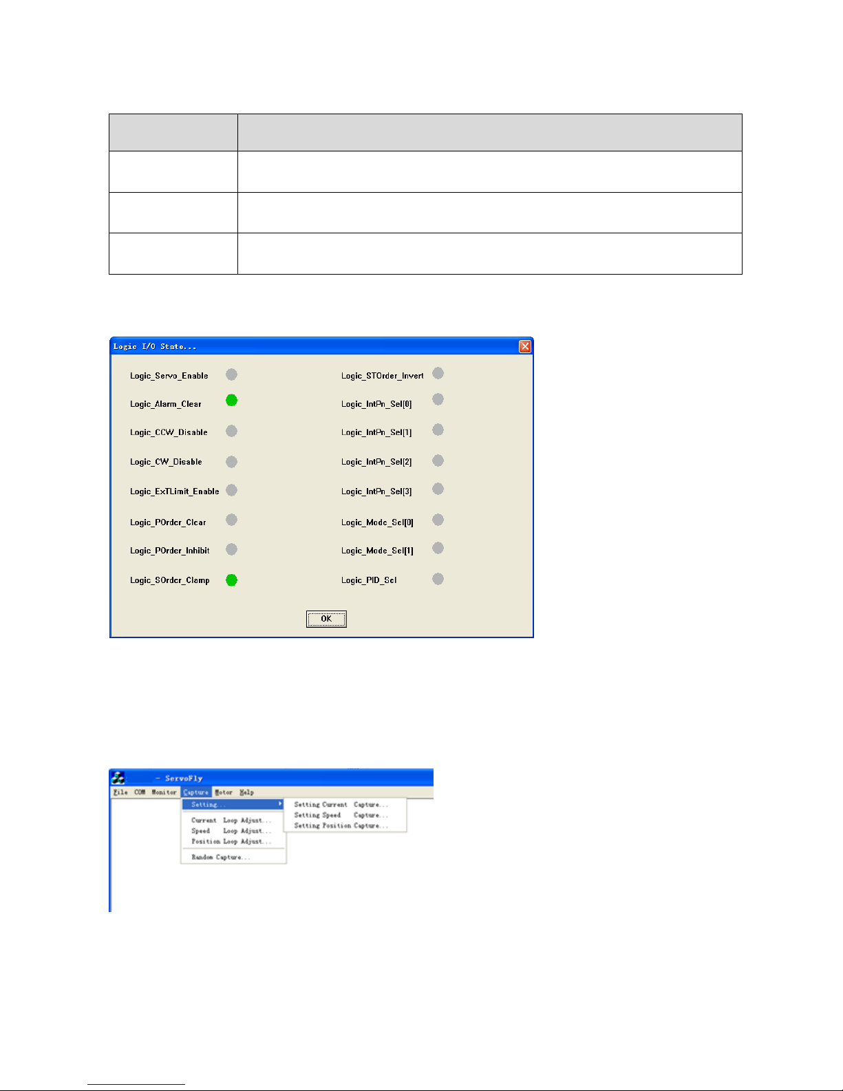
⑴The ―Logic State‖ item under the ―Monitor‖ menu is for the logical port status monitoring function.
⑵Function
Monitor the logical input status, green light indicates “ON”and grey light indicates “OFF”, please refer to
chapter 3 section 3.7 for details of logical input.
4.2.4 Oscillation control and running curve monitoring function
1. Oscillation control
In the picture, the items “Setting„”, “Current Loop Adjust„”, “Speed Loop Adjust„” and “Position
Loop Adjust„” are for oscillation control, this function is only for factory testing use, wrong operation may
cause damage, please DO NOT use this function.

18
BONMET motion GmbH/www.bonmet.com/www.bonmet.de
2. Running curve monitoring function
―Random Capture‖ menu is for the running curve monitoring function, customers can check the current loop
curve, speed loop curve and position loop curve.
4.2.5 Config function
There are two items ―Motor Config…‖ and ―Logic I/O Config…‖ under the ―Config‖menu. The “Aux Encoder
Config…” item DOES NOT open to customers.
1. Motor parameters adaptive function
⑴Click ―Basic Information…‖ and the following dialog will appear:
⑵Fill in the basic data (please don‘t fill in other parameters)
Item
Function
Rated Current(A)
Motor nominal current
Rs(ohm)
Phase resistance
Ls(mH)
Phase inductance
Ke(V/Krpm)
Back EMF
Note:This operation must be carried out by electrical engineer and the above parameters must be effective,
otherwise it would cause mistake or damage.
⑶Adaption
Click ―Auto Match‖ to start the adaption operation, as the following dialog appears, select the right direction(face
the motor shaft, ―CCW direction‖indicates counterclockwise direction and ―CW direction‖indicates clockwise0
direction), and then click ―OK‖.
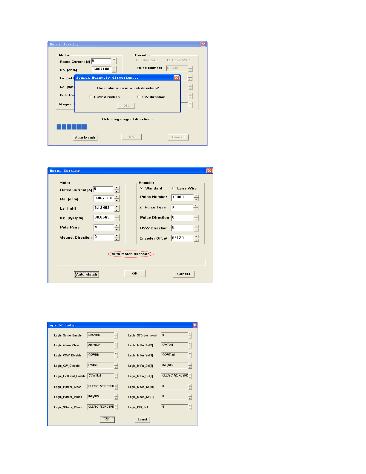
19
BONMET motion GmbH/www.bonmet.com/www.bonmet.de
The following dialog will appear as if the adaption is successful, please save the parameters to EEPROM and
power off, then power on again.
⑷If adption is not successful, maybe there is something wrong with the operation, please contact with out
technical staff.
2. Mapping function
⑴Click ―Logic I/O Config...‖ and the follow dialog will appear:
This manual suits for next models
1
Table of contents
Popular DC Drive manuals by other brands

Perception
Perception PEDAL DRIVE quick start guide

Lenze
Lenze L-force EYF A F04S06 Series Mounting instructions

Dynamatic
Dynamatic DCD-132 instruction manual

GFA
GFA ELEKTROMAT SI 6.160 FU-25,00 GA06/160MGDU installation instructions

YASKAWA
YASKAWA J1000 CIMR-JC series installation manual

Minarik
Minarik NRGD-4Q Series user manual

ABB
ABB ACS355 series Quick installation and start-up guide

Magnetek
Magnetek Impulse G+ series 4 quick start guide

Automationdirect.com
Automationdirect.com DURApulse GS10 quick start guide

EUCHIPS
EUCHIPS EUP200AD-1H12V-0 quick start guide

Masterflex
Masterflex I/P MFLX07591-20 operating manual

Aumuller
Aumuller KS15 Assembly instruction


