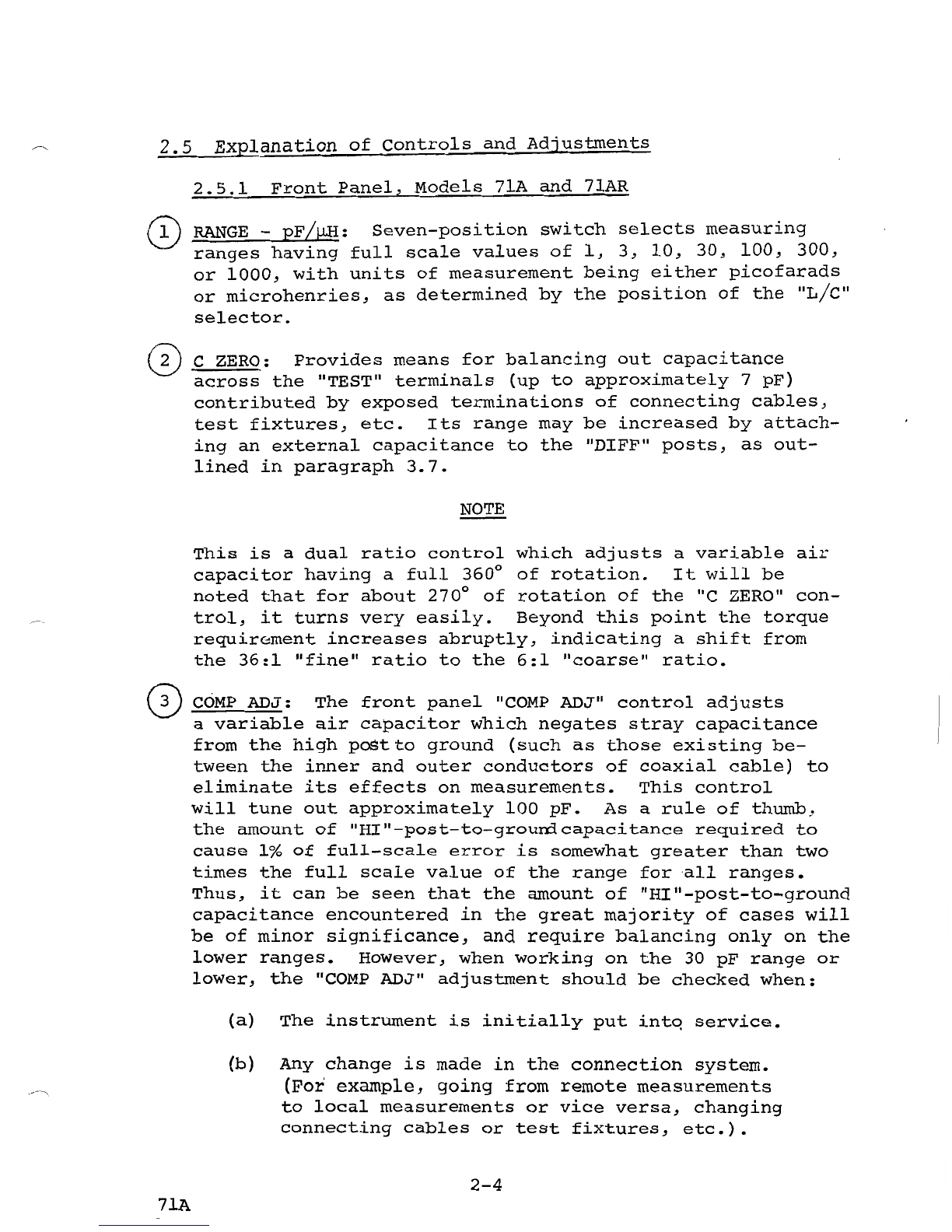
Boonton Electronics 71A, 71AR User manual

OPERATING INSTRUCTIONS
MODELS
71A & 71AR
capacitance/Inductance
Meter
•
o
~
co
....
...
FINE
...
...•.
C
~
AOJ
@)
TEL:
201-887-5110
TWX:
710-986-8241
BOONTONIIII
ROUTE
287
AT
SMITH
ROAD
!=~~~~'!~~~~
PARSIPPANY,
N.
J.-
07054
ADDENDUM
For
Model
7lA
and
7lA-R
' s
having
serial
numbers
400
and
below.
The
front
panel
control
on
these
instruments,
called
"Cable
Comp",
is
referred
to
in
this
book
as
"Comp
Adj".
The
terminals
on
these
units
called
"STD"
are
referred
to
in
this
book
as
"DIFF".
It
should
be
noted
that
these
differences
are
in
nomenclature
only,
and
in
all
respects,
electrical
functions
as
described
in
this
instruction
book
remain
the
same
for
all
units.
A-I
71A
a

Table
of
Contents
Page
1-1
Section
I
Specifications
Section
II
General
Description
2-1
2.1
General
Description~
Model
71A
2-1
2.2
General
Description~
Model
71AR
2-1
2.3
Location
of
controls
and
Adjustments~
Model
71A
2-2
2.4
Location
of
Controls
and
Adjustments~
Model
7lAR
2-3
2.5
Explanation
of
Controls
and
Adjustments
2-4
Section
III
Operating
Instructions
3-1
3.1
Initital
Installation
3-1
3.2
Capacitance
Measurements
3-3
3.3
Local
Capacitance
Measurements
3-3
3.4
Remote
Capacitance
Measurements
3-6
3.5
Increasing
Capacitance
Measuring
Range
3-10
3.6
Differential
Capacitance
Measurements
3-10
3.7
Extending
the
Range
of
the
C ZER0
Control
3-11
3.8
DC
Bias
for
Capacitance
Tests
3-11
3.9
Capacitance
Test
Signal
3-12
3.10
Capacitance
Calibration
Procedures
3-12
3.11
Inductance
Measurements
3-17
3.12
Connection
for
Inductance
Measurements
3-17
3.13
lnductance
Zero
Check
3-17
3.14
DC
output
3-18
3.15
IlMETER-OFp
lI
Switch
3-19
List
of
Replaceable
Parts
Following
Section
III
Schematics
Endfold
List
of
Figures
Figure
2-1
Location
of
Controls
and
Adjustments,
Model
71A
2-2
Figure
2-2_
Location
of
controls
and
Adjustments,
Model
7lAR
2-3
Figure
3-1
Correction
for
Series
Inductance
of
Connecting
Cables
3-9
71A
i

Table
of
Contents
(cont'd)
Figure
3-2
Circuit
for
Applying
High
Voltage
DC
Bias
to
Capacitance
Specimens
3-13
Figure
3-3
Connection
Errors
for
Inductance
Measurements
at
1
MHz
3-20
ii
71A.
b
SECTION I
Specifications
C~acitance
Measurements
{Three-terminal}
Range:
0
-to
1000
pF
in
7
Ranges;
lowest
range,
1
pF,
fs
Accuracy:
0.5%
of
reading
+
(0.5%
+
~
%)
fs
+
0.01
pF
Resolution:
0.25%
Inductance
Measurements
{Two-terminal}
Range:
0
to
1000
~H
in
7
ranges;
lowest
range,
1
~H
fs
L *
Accuracy:
0.5%
of
reading
+
(0.5%
+
~
% +
5b~lo)
fs
+
0.01
~H
( *
Where
L~H
=
Inductance
of
the
test
specimen)
Resolution:
0.25%
Test
Signal
Freguency:
1
MHz~
crystal
controlled
.
Level:
Capacitance
measurements,
15
mV;
Inductance
measurements,
less
than
1
mV
DC
Bias
(For
Capacitance
Measurements
Only)
External
bias
up
to
+200
V @
250
rnA
may
be
applied
at
rear
terminals;
bias
circuit
protected
from
overload
by
250
rnA
fuse
DC
Analog
Output
Level:
0
to
100
mV
or
0
to
300
mV
depending
on
full
scale
numerics;
also
:> 1 V
fs
for
loads
:>
10
MO
Linearity:
0.1%
of
reading
+
0.005%
fs
Response
Time:
10
milliseconds
(approx)
Primary
Power
117
or
234
V
(+10%),
50/60
cps:
40
watts
Physical
Dimensions
Model
7lA:
7
1/4/1
w x
10
1/4/1
d
xlI"
h;
weight
12
Ibs;
packed
for
shipment,
16
Ibs.
Model
71AR:
7"
x
19"
(panel
size);
depth
in
rack,
9";
weight,
14
Ibs;
packed
for
shipment,
21
lbs.
1-1
7lA
c
SECTION
II
General
Description
2.1
Model
7~
The
Model
71A
provides
instant,
direct-reading,
three-terminal
capacitance
measurements
and
two-terminal
inductance
measure-
ments
at
1 MHz.
The
measuring
capabilities
of
0
to
1000
pF
and
0
to
1000
~
are
each
covered
in
7
ranges
in
a
1-3-10
sequence.
The
internally
supplied
1
MHz
test
signal
is
crystal
controlled.
The
instrument
operates
with
low
test
levels
as
required
for
many
semiconductor
measurements.
Terminals
at
a
rear
panel
permit
application
on.
an
externally
supplied
dc
bias
up
to
±200
volts
to
the
test
specimen
on
capacitance
measurements
only.
Bias
cannot
be
provided
for
inductance
measurements.
A
linear
dc
output
is
available
at
rear
panel
terminals
which
is
proportional
to
the
meter
reading.
This
output
extends
the
range
of
application
beyond
laboratory
measurements
to
include
production
testing
as
well
as
a
variety
of
control
functions.
2.2
Model
7lAR
The
Model
7lAR
provides
the
performance
characteristics
of
the
Model
7lA
in
rack-mounting
form.
In
every
respect
its
electrical
specifications
are
identical
to
those
of
the
bench
unit.
In
addition,
the
Model
7l-lA
Standard
Capacitor
is
incorporated
in
the
Model
7lAR
and
is
switched
into
service
by
a
front
panel
selector.
** *
For
the
location
and
explanation
of
all
controls
and
adjust-
ments
of
the
Models
71A
and
71AR,
see
pages
2-2
through
2-7.
2-1
7lA
c

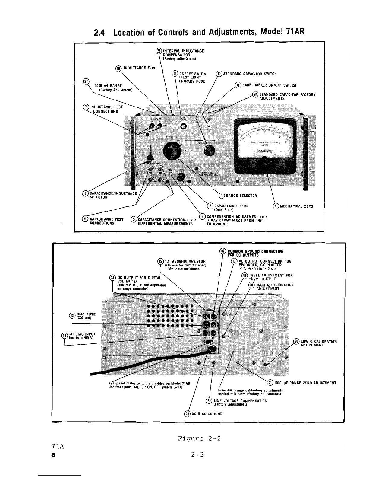
2.4
Location
of
Controls
and
Adjustments,
Model
71
AR
26
INDUCTANCE
ZERO
STANDARD
CAPACITOR
SWITCH
27
15
t.l
MEGOHM
RESISTOR
Remove
for
dvm's
having
1 Ma
input
resistance
DC
OUTPUT
FOR
DIGITAL
VOLTMETER
(100
mV
or
300
mV
depending
on
range
numerics)
12
DC
BIAS
INPUT
(up to ±200 V)
COMMON
GROUND
CONNECTION
FOR
DC
OUTPUTS
17
DC
OUTPUT
CONNECTION
FOR
RECORDER,
X·Y
PLOTTER
>1
V fnrJnads >10 M!l
LEVEL
ADJUSTMENT
FOR
"DVM"
OUTPUT
19
HIGH
Q
CALIBRATION
ADJUSTMENT
LOW
Q
CALIBRATION
ADJUSTMENT
21
lODD
pF
RANGE
ZERO
ADJUSTMENT
Individual
range
calibration
adjustments
behind this plate (factory adjustments)
LINE
VOLTAGE
COMPENSATION
(Factory Adjustment)
Figure
2-2
71A
a
2-3
2.5
Explanation
of
Controls
and
Adjustments
2.5.1
Front
Panel,
Models
7lA
and
71AR
RANGE
-
pF!~:
Seven-position
switch
selects
measuring
ranges
having
full
scale
values
of
1,
3,
10,
30,
100,
300,
or
1000,
with
units
of
measurement
being
either
picofarads
or
microhenries,
as
determined
by
the
position
of
the
"L/C"
selector.
C ZERO:
Provides
means
for
balancing
out
capacitance
across
the
"TEST"
terminals
(up
to
approximately
7
pF)
contributed
by
exposed
terminations
of
connecting
cables,
test
fixtures,
etc.
Its
range
may
be
increased
by
attach-
ing
an
external
capacitance
to
the
"DIFF"
posts,
as
out-
lined
in
paragraph
3.7.
NOTE
This
is
a
dual
ratio
control
which
adjusts
a
variable
air
capacitor
having
a
full
360
0
of
rotation.
It
will
be
noted
that
for
about
270
0
of
rotation
of
the
"c
ZERO"
con-
trol,
it
turns
very
easily.
Beyond
this
point
the
torque
requirGment
increases
abruptly,
indicating
a
shift
from
the
36:1
"fine"
ratio
to
the
6:1
"coarse"
ratio.
COMP
ADJ:
The
front
panel
"COMP
ADJ"
control
adjusts
a
variable
air
capacitor
which
negates
stray
capacitance
from
the
high
postto
ground
(such
as
those
existing
be-
tween
the
inner
and
outer
conductors
of
coaxial
cable)
to
eliminate
its
effects
on
measurements.
This
control
will
tune
out
approximately
100
pF.
As
a
rule
of
thumb,
the
amount
of
"HI"-post-to-grourrlcapacitance
required
to
cause
1%
of
full-scale
error
is
somewhat
greater
than
two
times
the
full
scale
value
of
the
range
for
all
ranges.
Thus,
it
can
be
seen
that
the
amount
of
"HI"-post-to-ground
capacitance
encountered
in
the
great
majority
of
cases
will
be
of
minor
significance,
and
require
balancing
only
on
the
lower
ranges.
However,
when
working
on
the
30
pF
range
or
lower,
the
"COMP
ADJ"
adjustment
should
be
checked
when:
(a)
The
instrument
is
initially
put
intq
service.
(b)
Any
change
is
made
in
the
connection
system.
(For
example,
going
from
remote
measurements
to
local
measurements
or
vice
versa,
changing
connecting
cables
or
test
fixtures,
etc.).
2-4
7lA
(c)
-Measuring
a
standard
capacitor.
(d)
Testing
a
specimen
having
markedly
different
"HI"-to-ground
capacitance
than
those
tested
previously
with
a
given
connection
system
(as
caused
by
considerable
differences
in
internal
construction,
encasing,
or
terminations).
~
CAPACITANCE
TEST:
BNC
connectors
for
the
test
specimen.
Measurements
may
be
made
either
locally
or
remotely
by
means
of
coaxial
cables.
CAPACITANCE
DIFF:
A
given
capacitance
connected
to
the
"TEST"
terminals
produces
an
accurately
calibrated
up-scale
reading.
Attaching
the
same
capacitance
to
the
"DIFF"
post
causes
a
comparable
down-scale
reading.
These
connections
are
useful
for
such
functions
as
making
differential
capaci-
tance
measurements,
extending
the
measuring
range
upwards,
or
extending
the
range
of
the
"c
ZERO"
control.
There
are
certain
limitations
on
the
use
of
the
"DIFF"
posts
which
are
detailed
in
paragraphs
3.5, 3.6,
and
3.7.
~
L/c:
This
switch
selects
a
condition
for
measurement
of
either
inductance
or
capacitance.
INDUCTANCE:
Test
terminals
for
inductance
measurements.
Measurements
should
be
made
directly
at
the
terminals.
Use
of
even
short
test
leads
should
be
avoided,
if
possible.
<:~
ON
(PUSH):
The
main
power
switch
(push
for
on,
pull
for
.
off)
i
the
translucent
red
button
serves
as
the
pilot
light.
This
assembly
also
contains
the
primary
power
fuse,
which
may
be
removed
by
rotating
the
black
ring
counterclockwise
and
withdrawing
the
fuse
holder.
~
MECHANICAL
ZERO:
This
adjusts
the
meter
pointer
to
a
mechanical
zero.
It
should
be
checked
with
the
instrument
switched
off.
I
I
@ OPERATE/CAL
l/CAL
2
(Model
7lAR
only):
For
measuring,
th~s
selector
is
left
in
the
lIOPERATElI
position.
Set
the
"CAL
1"
and
"CAL
2",
it
switches
in
the
internal
100
pF
standard
capacitor
for
high-Q
and
low-Q
calibration
checks,
respec~ively.
(See
paragraph
3.10.4.)
METER
ON/OFF
(Model
71AR
only):
There
is
no
interaction
between
the
indicating
meter
and
the
dc
output
except
for
a
small
counter-emf
from
the
moving
coil
of
the
meter
move-
2-5
7lA
mente
with
varying
meter
readings,
this
emf
may
show
up
as
slight
irregularities
in
the
dc
output:
switching
the
meter
off
eliminates
this.
In
addition,
switching
the
meter
off
eliminates
needless
wear
of
the
meter
movement
when
the
dc
output
is
used
for
widely
varying
test
values.
(In
the
Model
71A,
this
function
is
performed
by
the
rear!
panel
"METER
ON/OFF"
switch,
control
#22.)
This
control
is
inoperative
on
the
71A-R.
2.5.2
Rear
Panel,
Models
71A
and
71AR
±
BIAS:
This
terminal
and
BIAS
GND
(#23)
provide
for
appli-
cation
of
the
dc
bias
voltage
up
to
±200
volts
at
250
rnA
to
the
capacitance
test
specimen.
Bias
voltage
appears
across
both
"TEST"
and
"DIFF"
terminals.
FUSE:
250
rnA
fuse
prevents
internal
damage
in
case
the
bias
voltage
is
short-circuited
at
the
"TEST"
or
"DIFF"
terminals
either
by
accidental
contact
or
by
a
shorted
test
specimen.
See
paragraph
3.8·
for
further
details.
®
DVM+:
Connection
to
this
terminal
and
the
"GND"
terminal
(#16)
irrmediately
below
provides
a
dc
analog
of
the
measured
value
suitable
for
use
with
a
digital
voltmeter.
Output
for
full-scale
is
100
mV
or
300
mV
depending
upon
numerics
of
the
selected
range,
so
that
when
ranges
are
switched
the
dvm
follows
automatically.
~
1.1
Mn
RESISTOR:
For
dvm's
having
an
input
resistance
of
10
megohms
or
greater,
this
resistor
should
be
left
in
posi-
tion.
For
dvm's
having
an
input
resistance
of
1
megohm,
it
should
be
removed.
GND:
Ground
connection
for
DVM
or
REC
output.
REC:
connection
to
this
terminal
and
to
the
"GOO"
terminal
(#16)
provides
a
linear
analog
output
of
the
measured
value,
whose
level
varies
from
0
to
approximately
1.7
volts
(into
loads
greater
than
10
megohms)
for
full-scale
on
all
ranges.
DVM
ADJ:
This
control
adjusts
the
level
of
the
de
analog
output
so
that
the
dvm
will
be
in
agreement
with
a
standard
capacitor.
See
paragraph
3.14.4.
CAL
1:
Calibration
adjustment
for
high
Q
measurements.
For
calibration
procedures,
see
paragraph
3.10.
2-6
71A
b
CAL
2:
Calibration
adjustment
for
low
Q
measurements.
For
calibration
procedures,
see
paragraph
3.10.
1000
pF
ZERO:
Zero
adjustment
for
1000
pF
range.
Once
set
on
initial
installation,
this
control
will
rarely
need
re-
adjustment.
However,
since
the
setting
of
this
control
is
vital
to
proper
operation
for
either
capacitance
or
induc-
tance
measurements,
it
is
recommended
that
it
be
checked
periodically.
(See
paragraph
3.1.4,
(f)
&
(g)
for
procedure.)
Line
Voltage
Compensation:
Factory
adjustment
to
assure
insensitivity
to
line
voltage
changes
from
105
to
125
V,
ac.
GND:
Ground
connection
for
dc
bias
input.
METER
ON/OFF,
Model
71A
only):
There
is
no
interaction
between
the
indicating
meter
and
the
dc
output
except
for
a
small
counter-emf
from
the
moving
coil
of
the
meter
move-
ment.
With
varying
meter
readings,
this
emf
may
show
up
as
slight
irregularities
in
the
dc
output~
switching
the
meter
off
eliminates
this.
NOTE:
In
the
Model
71A.R
this
function
is
performed
by
front
panel
switch
#11.
While
this
swi~ch
is
present
at
the
rear
of
the
Model
71AR,
it
is
disabled.
2.5.3
Model
7lA
z
Left
side~
Model
7lAR,
Top
INTERNAL
INDUCTANCE
COMPENSATION:
This
factory
adjustment
compensates
for
inductance
of
internal
wiring.
Pre-set
at
the
factory,
this
control
does
not
require
readjustment.
L ZERO:
This
control
provides
a
means
for
zeroing
the
in-
strument
on
the
1
~H
range
in
accordance
with
the
procedure
outlined
in
paragraph
3.13.
1000
WH
CALIBRATION:
This
control
provides
means
for
in-
dividually
calibrating
the
1000
~
range~
it
is
pre-set
at
the
factory
and
does
not
require
readjustment.
Adjustments
for
the
internal
100
pF
standard
capacitor.
These
are
set
at
the
factory
and
do
not
require
readjustment.
2-7
7lA
b
L SECTION
III
Operating
Instructions
3.1
Initial
Installation
3.1.1
Unpacking
On
unpacking~
inspect
the
instrument
for
possible
damage
in
transit.
If
the
instrument
is
damaged~
contact
your
local
Sales
Engineering
Representative
or
the
factory
(see
title
page
for
factory
address)
for
further
instructions.
If
no
damage
is
found~
the
instrument
may
be
put
into
service
by
the
following
procedure:
3.1.2
Mechanical
Zero
Adjustment
with
the
instrument
unpowered
and
in
a
normal
operating
position~
check
to
see
that
the
indicator
needle
rests
at
zero.
If
not~
set
to
zero
by
adjusting
the
mechanical
zero
control
on
the
meter
housing.
3.1.3
Turn-on
Procedure
and
Warm-up
Plug
the
instrument
into
a
source
of
117
V (±10%)
50/60
HZ
power
and
push
the
front
panel
ON
button.
(Note:
The
translucent
red
center
button
of
the
ON
switch
also
serves
as
the
pilot
light.
This
switch
is
turned
off
by
pulling
the
outer
black
disk
outward.
It
should
be
noted
that
this
switch
also
serves
as
the
fuse
holder.
(To
remove
the
fuse~
turn
the
switch
off~
twist
the
black
ring
counterclockwise~
and
withdraw
the
assembly.)
The
instrume~t
may
be
operated
approximately
30
seconds
after
turn-on.
However~
for
maxi-
mum
accuracy~
a
warm-up
of
approximately
a
half-hour
should
be
allowed.
3.1.4
Initial
Installation
Checks
and
Adjustments
3.1.4.1
General
Before
the
instrument
is
put
into
service,
there
are
several
initial
checks
which
should
be
made~
and~
if
necessary,
adjustments
perfor.med:
3.1.4.2
(a)
Allow
an
initial
warm-up
of
a
half
hour.
(b)
Set
the
Llc
selector
to
C.
3-1
71A
c
(c)
With
the
instrument
on
the
1
pF
range~
and
no
specimen
connected
to
the
"TEST"
terminals,
set
the
indicator
to
about
75%
of
full
scale
using
the
front
panel
"c
ZERO"
control.
(d)
Adjust
the
front
panel
"COMP
ADJ"
control
for
a
peak
reading.
(Readjust
the
"c
ZERO"
control
to
keep
indications
on-scale
if
necessary)
.
(e)
Having
achieved
a
peak
reading~
return
the
indicator
to
zero
using
the
"c
ZERO"
control.
(f)
Switch
to
the
1000
pF
range~
and
observe
the
zero
position
of
the
indicator.
If
required~
set
to
zero
using
the
"1000
pF
ZERO"
at
the
rear
panel.
(g)
Switch
one
range
at
a
time
back
to
the
1
pF
range,
observing
the
zero
position
of
the
indicator
for
each
range.
If
the
zero
posi-
tion
shifts
appreciably
for
any
range,
re-
peat
steps
(c)
through
(g).
When
properly
adjusted,
the
zero
position
should
be
con-
stant
for
all
ranges.
NOTE
Once
properly
set,
the
"1000
pF
ZERO"
rarely
needs
readjustment.
However~
since
its
set-
ting
is
essential
to
the
proper
operation
of
the
instrument
for
either
capacitance
or
inductance
measurement,
it
is
advisable
to
check
it~
following
steps
(f)
and
(g)
above,
at
fairly
frequent
intervals.
(h)
Stretch
a
short
length
of
#22
copper
wire
between
the
"INDUCTANCE"
terminals.
(j)
Switch
the
"L/C"
switch
to
the
"L"
posi-
tion.
The
indicator
should
rest
one
minor
division
up-scale
from
zero.
If
not~
ad-
just
for
this
reading
using
the
"L
ZERO"
control
(the
center
adjustment
on
the
left
side
of
the
instrument).
3-2
71A
d
3.2
capacitance
Measurements
With
the
front
panel
IIL-C
II
selector
in
the
"C
II
position~
the
Models
71A
and
71AR
measure
the
"direct"
capacitance
of
the
test
specimen.
(The
instruments
ignore
stray
capacitance
from
the
"LO"
post
to
ground.
Up
to
about
100
pF
of
capaci-
tance
from
the
"HI"
post
to
ground
can
be
nulled
by
adjust-
ment
of
the
"COMP
ADJ"
control.
As
a
result~
the
Models
71A
and
71AR
measure
only
the
capacitance
appearing
between
the
"HI"
and
"LO"
terminals.)
The
measurements
may
be
made
either
at
the
"TEST"
terminals
or
remotely
by
connecting
the
specimen
or
test
fixture
via
'
coaxial
cables
to
the
"TEST"
terminals.
By
use
of
both
the
"DIFF"
and
"TEST"
terminals
differential
capacitance
measure-
ments
may
be
made
within
certain
limitations.
3.3
Local
Capacitance
Measurements
3.3.1
Connections
for
Local
Measurements
While
the
capacitance
connectors
of
the
Models
7lA
and
7lAR
are
intended
primarily
for
attachment
of
coaxial
cables~
tests
may
readily
be
made
locally
by
connecting
the
speci-
men
directly
to
the
te~inals.
A
pair
of
Type
UG-1090/U
or
comparable
BNC-to-binding-post
adapters
are
particularly
convenient
for
this
purpose~
although
for
quick
measurements
the
leads
of
the
component
may
be
simply
inserted
in
the
center
receptables
of
the
BNC
terminals.
NOTE
If
any
length
of
coaxial
cables
is
used
for
connection~
even
if
they
are
only
a
few
inches
in
length~
the
measurement
is
considered
not
local~
but
is
remote
and
the
instructions
of
paragraph
3.4
apply.
3.3.2
Checks
and
Adjustment
Prior
to
Making
Local
Measurements
There
are
three
controls
whose
adjustment
should
be
checked
before
measuring
at
the
terminals
of
the
Model
71A
or
71AR:
(a)
"1000
pF
ZERO"
(b)
"COMP
ADJ
II
(c )
"C
ZERO"
3-3
71A
d
3.3.2.1
111000
pF
ZERO"
Adjustment
The
111000
pF
ZERO"
control
is
located
at
the
rear
panel.
Its
setting
is
checked
by
switching
to
the
1000
pF
range
and,
with
no
specimen
attached
at
the
IITEST
If
terminals,
observing
the
rest
position
of
the
pointer.
If
it
does
not
read
zero,
follow
the
adjustment
procedure
outlined
in
paragraph
3.1.4,
(f)
and
(g).
3.3.2.2
IICOMP
ADJ
II
Peaking
Adjustment
Prior
to
measuring
at
the
IITEST
II
terminals,
the
IICOMP
ADJ"
peaking
adjustment
should
be
performed
as
follows:
(a)
Attach
any
terminal
adapters
or
connectors
to
be
used
for
subsequent
measurements
to
the
IITEST
II
terminals
and
set
the
"RANGE"
selector
to
the
1
pF
range.
(b)
Adjust
the
"c
ZERO"
control
for
a
reading
of
approximately
75%
of
full
scale.
(e)
Adjust
the
IICOMP
ADJ
II
control
for
a
maximum
reading.
(Readjust
the
"c
ZERO"
control
to
keep
deflections
on
scale
if
required.)
(d)
After
peaking,
zero
the
pointer
using
the
lie ZERO"
control.
Once
adjusted,
the
"COMP
ADJ
II
control
need
not
be
re-
adjusted
(although
periodic
checking
during
extended
periods
of
operation
is
advisable)
unless
some
change
in
either
the
method
of
connection
or
the
nature
of
the
test
samples
substantially
affects
the
stray
capacitance
from
the
"HI"
post
to
ground.
In
such
cases,
readjust-
ment
pf
the
"COMP
ADJ"
control
is
required.
The
above
"COMP
ADJ"
adjustment
procedure
will
suffice
for
the
majority
of
measurements
at
the
terminals
for
all
ranges.
However,
to
obtain
the
greatest
possible
accuracy
when
measuring
high
Q
(>10)
components
on
the
1,
3,
10
or
30
pF
range,
and
when
the
test
sample
has
significant
capacitance
from
the
IIHI JI
post
to
ground,
the
following
procedure
should
be
follows:
(a)
Attach
whatever
terminal
adapters
or
connectors
are
to
be
used
in
subsequent
measurements
to
the
"TEST"
posts
and
connect
a
specimen
typical·of
3-4
7lA
those
to
be
measured.
If
no
connectors
are
to
be
used,
insert
the
leads
of
the
specimen
in
the
center
conductors
of
the
"TEST"
posts.
(b)
Set
the
"RANGE"
selector
to
the
lowest
range
on
w.mch a
reading
of
approximately
75%
of
full
scale
is
possible.
(On
the
lower
ranges
the
"C ZERO"
control
may
be
of
help
in
obtaining
this
reading.)
(c)
Adjust
the
"COMP
ADJ"
for
peak
reading.
(Readjust
the
tIC
ZERO"
to
keep
deflections
on
scale
if
necessary.)
(d)
Disconnect
the
specimen
from
the
low
post,
leav-
ing
any
terminal
adapters
to
be
used
for
subse-
quent
tests
in
position;
zero
the
pointer
with
the
"c
ZERO"
control.
3.3.2.3
IIC ZERO"
Adjustment
The
front
panel
"c
ZERO"
adjustment
is
checked
by
switching
to
the
1
pF
range.
with
the
"COMP
ADJ"
control
properly
peaked
and
no
specimen
across
the
test
terminals,
observe
the
rest
position
of
the
pointer.
If
necessary,
the
pointer
should
be
brought
to
zero
using
the
front
panel
control.
Any
terminal
adapters
to
be
used
in
subsequent
measurements
should
be
left
installed
for
this
adjustment.
with
"100
pF
ZERO"
and
"c
ZERO"
controls
properly
set,
the
instrument
will
be
correctly
zeroed
for
all
ranges,
assuming
the
"COMP
ADJ"
control
is
properly
adjusted.
It
is
advisable
to
check
the
1
pF
zero
position
periodi-
cally
during
the
course
of
operation,
particularly
if
working
on
the
1
or
3
pF
ranges.
NOTE
The
front
panel
"c
ZERO"
control
is
a
dual
ratio
control
which
adjusts
a
variable
air
capacitor
having
a
full
360
0
of
rotation.
It
will
be
noted
that
the
"C
ZERO"
control
turns
very
easily
for
about
270
0
of
rotation.
At
this
point
the
torque
requirement
increases
abruptly,
indicating
a
shift
from
the
36:1
"fine"
adjustment
to
the
6:1
"coarse"
adjustment.
3-5
71A
3.4
Remote
Capacitance
Measurements
3.4.1
Connections
for
Remote
Measurements
A
test
specimen
or
a
test
fixture
m~cted
to
the
"TEST"
terminals
by
coaxial
cables.
RG-62
is
particularly
recommended
for
this
purpose
because
0
its
low
capacitance.
To
minimize
errors
in
measurement
resulting
from
the
series
inductance
of
the
coaxial
cable,
the
length
of
each
of
the
two
cables
should
be
less
than
approximately
5
feet
on
the
1,
3,
and
10
pF
ranges,
with
shorter
lengths
on
higher
ranges.
Figure
3-1,
which
indicates
correction
factors
for
cable
inductance,
may
be
used
as
a
guide
in
selecting
prac-
tical
cable
lengths.
3.4.2
Initial
Adjustment
for
Remote
Measurements
There
are
three
controls
whose
adjustment
should
be
checked
before
making
remote
measurements
with
this
instrument:
(a)
"1000
pF
ZERO"
(b)
"COMP
ADJ"
(c)
rIC ZERO"
3.4.2.1
"1000
pF
ZERO"
Adjustment
The
"1000
pF
ZERO"
control
is
located
at
the
rear
panel.
Its
setting
is
checked
by
switching
to
the
1000
pF
range
and,
with
no
specimen
attached
at
the
"TEST"
terminals,
observing
the
rest
position
of
the
pointer.
If
it
does
not
read
zero,
follow
the
adjustment
procedure
outlined
in
paragraph
3.1.4,
(f)
and
(g).
3.4.2.2
"COMP
ADJ"
Peaking
Adjustment
Prior
to
measuring
remotely,
the
"COMP
ADJ"
peaking
adjust-
ment
must
be
performed
as
follows:
(a)
Connect
the
coaxial
cables
and
test
fixture
(if
any)
to
be
used
in
subsequent
measurements
to
the
"TEST"
terminals.
Set
the
range
selector
to
the
1
pF
range.
(b)
Adjust
the
"e ZERO"
control
for
a
reading
of
approximately
75%
of
full
scale.
3-6
7lA
(c)
Adjust
the
"CaMP
ADJ"
control
for
a
maximum
reading.
(Readjust
the
"e
ZERO"
control
to
keep
deflections
on
scale
if
required).
(d)
After
peaking~
zero
the
pointer
using
the
"c
ZERO"
control.
Once
adjusted~
the
"CaMP
ADJ"
control
need
not
be
re-
adjusted
for
some
time
(although
periodic
checking
during
extended
periods
of
operation
is
advisable)
unless
some
change
in
either
the
connection
system
or
the
nature
of
the
test
samples
substantially
effects
the
stray
capacitance
from
the
"HI"
post
to
ground.
In
such
cases~
readjustment
of
the
"CaMP ADJ"
control
is
required.
The
above
"CaMP
ADJ"
adjustment
procedure
will
suffice
for
the
majority
of
remote
measurements.
However,
to
obtain
the
greatest
possible
accuracy
when
using
the
l~
3~
10
or
30
pF
range,
and
when
the
specimen
has
sig-
nificant
capacitance
from
the
"HI"
post
to
ground,
the
following
procedure
should
be
followed:
(a)
Attach
the
coaxial
cables
and
test
fixture
(if
any)
which
are
to
be
used
in
subsequent
measure
ments
to
the
"
..
TEST"
posts
and
connect
a
specimen
typical
of
those
to
be
measured.
(b)
Set
the
"RANGE"
selector
to
the
lowest
range
on
which~
using
the
"C ZERO"
control~
a
reading
of
approximately
75%
of
full
scale
is
possible.
(c)
Adjust
the
"CaMP
ADJ"
for
peak
reading.
(Re-
adjust
the
"c
ZERO"
to
keep
deflections
on
scale
if
necessary.)
(d)
Disconnect
the
cable
at
the
low
post
and
zero
the
pointer
with
the
lie
ZERO"
control
(see
paragraph
3.4.2.3
below).
3.4.2.3
"C
ZERO"
Adjustment
The
front
panel
"e
ZERO"
adjustment
is
checked
by
switch-
ing
to
the
1
pF
range.
with
the
"CaMP ADJ"
control
properly
peaked
and
no
specimen
across
the
test
terminals
observe
the
rest
position
of
the
pointer.
If
necessary,
the
pointer
should
be
brought
to
zero
using
the
front
panel
"e ZERO"
control.
(The
coaxial
cables
and
test
3-7
71A

fixture
to
be
used
in
subsequent
measurements
should
be
attached
for
this
adjustment.)
with
the
111000
pF
ZERO"
and
"c
ZERO"
controls
properly
set,
the
instrument
will
be
correctly
zeroed
for
.all
ranges,
assuming
the
"COMP
ADJ
II
control
is
properly
adjusted.
It
is
advisable
to
check
the
1
pF
zero
position
periodi-
cally
during
the
course
of
operation,
particularly
if
working
on
the
1
or
3
pF
ranges.
NOTE
The
front
panel
IIC
ZERO"
control
is
a
dual
ratio
control
which
adjusts
a
variable
air
capacitor
having
a
full
360
0
of
rotation.
It
will
be
noted
that
the
"C
ZERO
II
control
turns
very
easily
for
about
270
0
of
rotation.
At
this
point
the
torque
requirement
increases
abruptly,
indicating
a
shift
from
the
36:1
IIfine
ll
adjustment
to
the
6:1
"coarse"
adjustment.
If
it
is
found
that
the
"c
ZERO"
range
is
inadequate
to
zero
out
the
external
capacitance,
its
range
may
be
extended
as
outlined
in
paragraph
3.7.
3.4.3
Errors
in
Capacitance
Measurements
Resulting
from
Series
Inductance
of
Connecting
Cables.
The
measured
capacitance,
Cm,
of
a
specimen
may
differ
from
the
true
capacitance,
Ct,
as
a
result
of
the
series
inductance
of
connecting
cables,
and
the
inductance
of
the
specimen.
The
error
will
be
noted
as
an
apparent
increase
in
capaci-
tance
value
in
accordance
with
the
following
expression:
Where
L =
the
combined
series
inductance
in
micro-
henries
of
BOTH
lengths
of
connecting
coaxial
cable
and
the
inductance
of
the
sample
(generally
small
with
respect
to
the
cable
inductance).
The
correction
chart
of
Figure
3-1
indicates
typical
cor-
rections
to
be
subtracted
from
the
mea$ured
value
for
a
pair
of
l-foot
cables
of
RG-62/U
at
1
MHz
for
test
values
3-8
71A
d
Table of contents
Popular Measuring Instrument manuals by other brands


Extech Instruments
Extech Instruments CO260 user manual

PCB Piezotronics
PCB Piezotronics P357B03 Installation and operating manual

Saveometer
Saveometer 2652 user guide

Alpha Moisture Systems
Alpha Moisture Systems DS1200-PDT user manual

National Metallic
National Metallic DIAL CALIPER instruction manual

PT
PT PT200P Operator's manual