Boonton 92E User manual
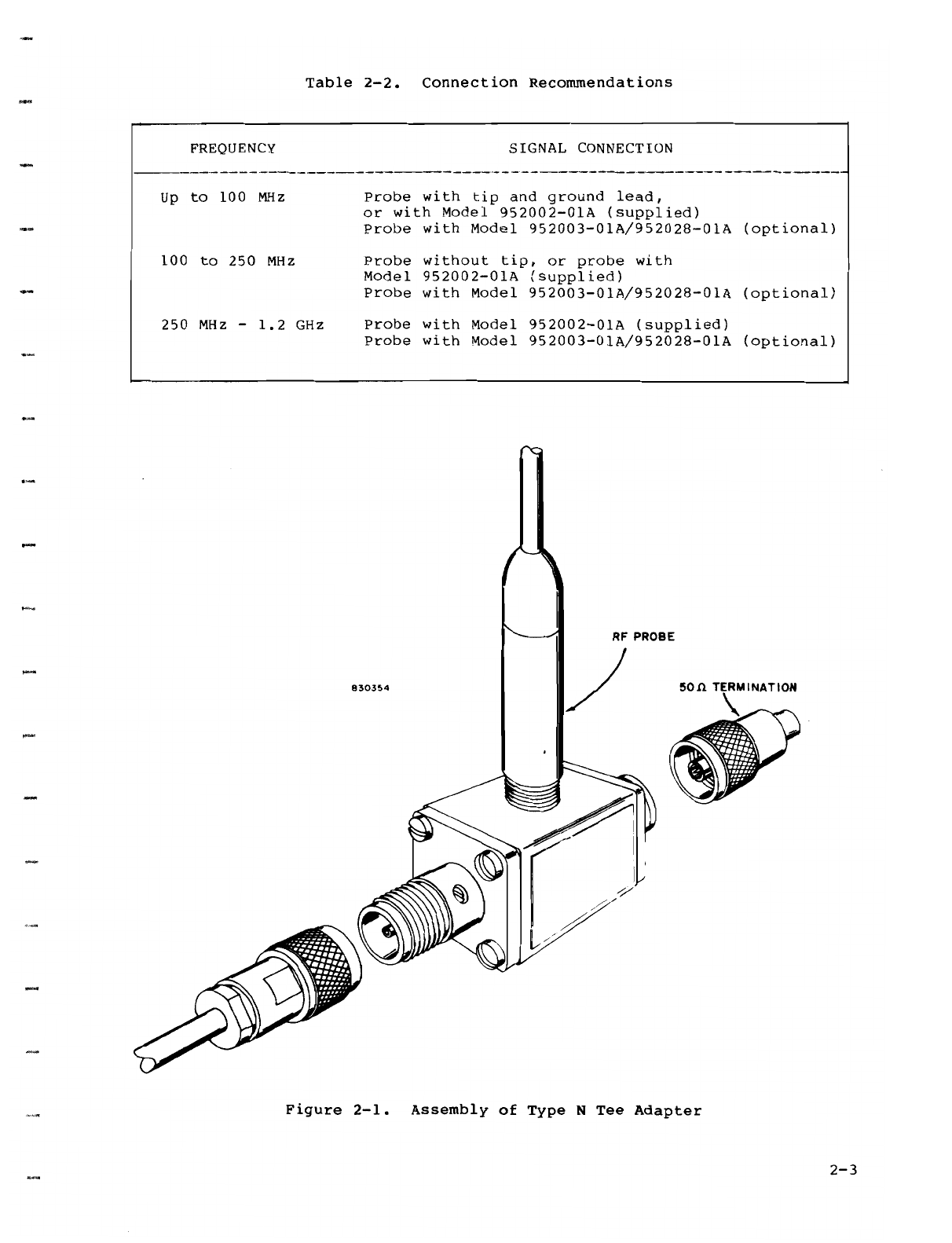
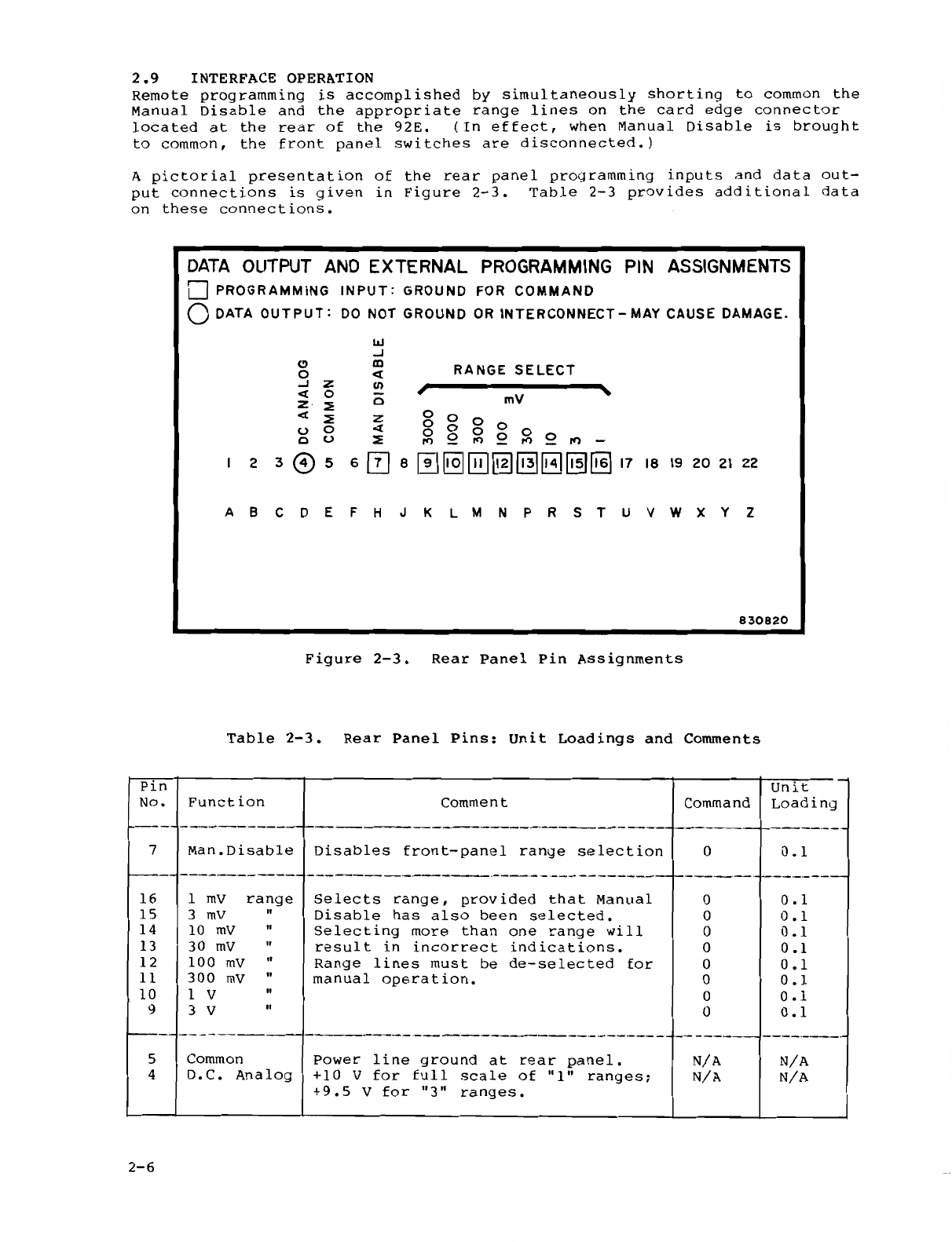
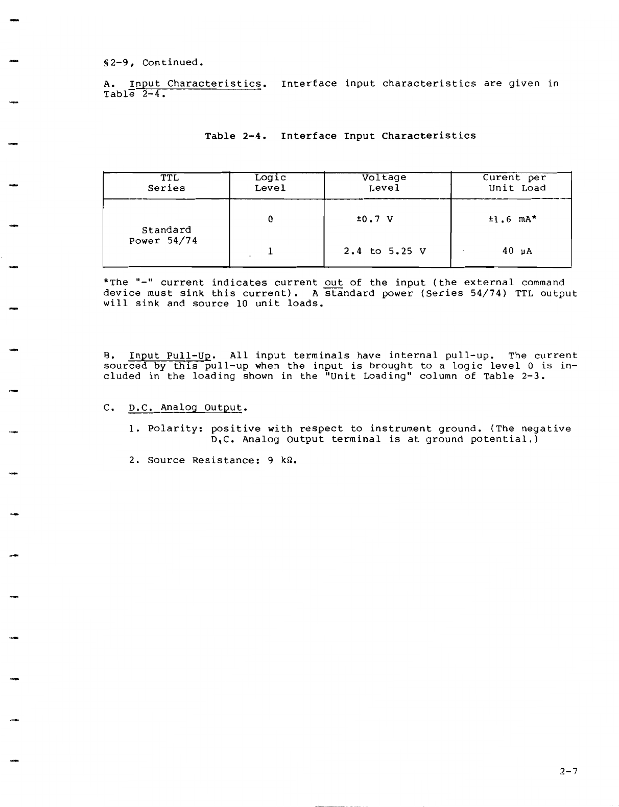
....
-
-
INSTRUCTION MANUAL
MODEL
92E
R.F. MILLIVOLTMETER
BOONTON
ELECTRONICS CORPORATION
Part
No.
982012-00A
791
ROUTE 10, RANDOLPH, NJ 07869
TELEPHONE:
201
-584·1077 TWX: 710-986-8215
Printed in U.S.A.
6/85

SAFETY
SUMMARY
The
following
general
safety
precautions
must
be
observed
during
all
phases
of
operation
and
maintenance
of
this
instrument.
Failure
to
comply
with
these
precautions
or with specific
warnings
elsewhere
in this
manual
violates
safety
~tandards
of
design,
manufactun.:.
and
intended
use
of
the
instrument.
Boonton
Electronics
assumes
no
liability
for
the
customer\
failure
to
comply
with
the~c
re4uirement~.
THE
INSTRUMENT MlIST
BF..
GROUNDED
To
minimize
shock
hazard
the
instrument
chassi:-.
and
cabinet
must
be
connected
lo
an
electrical
ground.
The
instrument
is
equipped
with
a
three
conductor.
three
prong
a.c.
power
cabk.
The
power
cable
must
either
be
plugged
into
an
approved
three-contact
dectrical
outlet
or
used with a
three-contact
to
a
two-contact
adapter
with
thdgreen)
grounding
wire firmly
connected
to
an
electrical
ground
at
the
power
outlet.
DO NOT OPERATE
THE
INSTRUMENT
IN
AN
EXPLOSIVE ATMOSPHERE.
Do
not
operate
the
instrument
in
the
presence
of
flammable
gases
or
fumes.
KEEP
AW
AY FROM
LIVE
CIRCUITS.
Operating
personnel
must
not
remove
instrument
covers.
Component
replacement
and
internal
adjust-
ments
must
be
made
by
quailfied
maintenance
pcrsonnd.
Do
not
replace
components
with
the
power
cable
connected.
Under
certain
conditions
dangerous
voltages
may
exist
C\en
though
the
power
cable was
removed.
therefore;
alway~
di~corrncct
power
and
dischargl'.
circuih
bl'.fore
touching
thew.
DO
NOT
SERVICE
OR
ADJlJST ALONE.
Do
not
attempt
internal
service
or
adjustment
unless
another
person.
capable
of
rendering
first
aid
and
resuscitation,
is
present.
DO
NOT
SUBSTITUTE PARTS
OR
MODIF"Y
INSTRUMENT.
Do
not
install
substitute
parts
or
perform
any
unauthori1ed
modification
of
the
insturment.
Return
the
instrument
to
Boonton
Electronics
for
repair
to
ensure
that
the safct;
leatures
an:
maintained.
SAFETY SYMBOLS.
This
safety
requirement
symbol
(located
on
the
rear
panel)
has heen
adopted
by tht·
International
Elcctrotechnical
Commi~~ion.
Documrnt
66
(Central
Office) J.
Para-
graph
5.3,
which
directs
that
and
imtrumenl
he
so
labeled
if.
for
the
correct
use ofthe
instrument.
it is necessary
to
refer t\l
the
imtruction
manual.
In this
case
it
is
recommended
tha\
refen.:ncc he madi:
to
the
inqruction
manual
when
connecting
the
instrument
to
rhe
proper
power
source.
Verify that the
correct
fuse is installed
for
the
power
available.
and
that
the
switch
on
the
rear
panel
is
'ct
to
the
applicahle
operating
voltage.
The
CAUTION
sign
denotes
a
ha1ard.
It ca
lb
at1cntion
to
an
operation
procedure,
practice,
or
the
like,
which.
if
not
correctly
performed
or
adhered
to.
could
result in
damage
to
or
destruction
of
part
or
alt
of
the
eyuipment.
Do
not
proceed
bcyond
a
CAUTION
sign until the
indicated
conditions
art• fully
understood
and
met.
WARNING •
The
WARN
ING
sign
denotes
a
ha1ard.
It
calls
attention
to
an
operation
procedure,
I
practice,
or
the
like.
which.
if
not
correctly
performed
or
adht"red
to,
could
result in
•------
111
injury
or
loss
of
life.
Do
not
proceed
beyond
a
WARNING
sign until
the
indicated
conditions
are
fully
understood
and
met.
f
Indicates
dangerous
voltages.

-
-
-
T A B L E 0 F C 0 N T E N T S
SECTION I - GENERAL INFORMATION
Paragraph
1-1
1-2
1-3
1-4
1-5
1-6
2-1
2-2
2-3
2-4
2-5
2-6
2-7
2-8
2-9
3-1
3-2
4-1
4-2
4-3
4-4
4-5
4-6
Introduction
Safety
Notice
Description
Accessories
Furnished
••••••
Options
and
Accessories
Available
Compatibility
of
Accessories
Specifications
•••.•..••••.••
SECTION
II
INSTALLATION
AND
OPERATION
Installation
.•.•.•••••.••••.•..••
Operating
Controls
and
Indicators
Safety
Requirement
Symbol
Initial
Operating
Procedures
Operating
Notes
••
,
••••••••
D.C.
Output
••.•
,
.••••••
Low
Frequency
Measurements
Correction
Curves
for
Models
952003-0lA
and
952007-0lA
Interface
Operation
.....
,
..................•..........
SECTION
III
-
THEORY
OF OPERATION
Introduction
••.••.•••..••••.•
Circuits:
Detailed
Discussion
A..
Sensor
B.
Chopper
c.
Amplifier
D.
Demodulator
E.
Driver
F.
Clock
......
G.
Ranging
and
Prog
r
arnm
i
ng
H.
Shaping
I•
Power
Supply
SECTION
IV
-MAINTENANCE
Introduction
••.••..•
Periodic
Calibration
Power
Supply
Checks
Calibration
Check
Calibration
Procedure
Troubleshooting
•.••••
A.
Cover
Removal
B.
Replacement
of
R.F.
C.
Probe
Tests
.•••..•
Probes
1.
2.
3.
S.W.R.
Measurement
Frequency
Response
Swept
Frequency
Response
and
S.W.R.
Page
...
l-1
.l-1
.l-1
.l-3
.•
1-3
.1-4
.l-4
• •
2-1
••.
2-1
•
2-2
••
2-2
.2-2
.2-4
••••
2-5
.2-5
•••
2-6
.1-1
.....
1-
2
••
1-2
.1-2
.1-2
.1-3
..•
1-3
•••
1-
3
.1-4
.1-4
.1-7
.4-1
•••
4-1
.4-1
•••
4-1
•••
4-2
••
4-5
.4-5
.4-5
• •
4-5
••
4-5
•••
4-6
.4-7
i

SECTION V -
PARTS
LIST
Paragraph
Page
5-1
Introduction
...................................................
••
5-1
SECTION VI -
SCHEMATIC
DIAGRAMS
6-1
Schematic
Diagrams,
Table
of
Contents
••••••••••••••••••••••••••••
6-1
Figure
1-1
1-2
2-1
2-2
2-3
3-1
3-2
3-3
3-4
3-5
3-6
4-1
4-2
4-3
LIST
OF
ILLUSTRATIONS
Page
Input
Resistance
of
Model
92001-02A
R.F.
Probe
••••••••••••
••
1-6
Input
Capacitance
of
Model
92001-02A
R.F.
Probe
•••••••••••••••
1-7
Assembly
of
Type
N
Tee
Adapter
••••••••••••••••
, , • , ,
•••••••••
, • ,
••
2-3
Correction
Curves
for
Type
N
Tee
Adapters
•••••
•
•••••••••••••
2-5
Rear
Panel
Pin
Assignments
•••••••••••••••••••••
•
••••••••
2-6
Simplified
Block
Diagram
••••••••••••••••••••••••••••••••
•••••••
3-1
Block
Diagram:
Amplifier
Section
••••••••••••••••••••
.3-3
Block
Diagram:
Demodulator
and
Driver
•••••••
, • • • • • • • • ,
••••
, • , •
3-4
Block
Diagram:
Ranging
Circuitry
••••••••••••••••
3-5
Block
Diagram:
Shaping
Section
••••••••
..3-6
Block
Diagram:
Power
Supply
•••••••••••••••••
••
3-8
Adjustment
Locations
and
Descriptions
••••••••••••••••••••••••••
4-3
Frequency
Response
Test
Setup
• . • • • • • • • • • • • • • • • • ,
•••••••••
4-6
Swept
Frequency
Response
Test
Setup
••••••••••••••.•••••••••••••
4-8
LIST
OF
TABLES
Page
Crest
Factors
. . . . . . . . . . . . . . . . . . . . . . . . . . . . . . . . .
................
.
1-7
Table
1-1
2-1
2-2
2-3
2-4
5-1
5-2
Operating
Controls,
Indicators
and
Connectors
••••••••••••••••
2-1
Connect
ion
Recommendations
••••••••••
,
•••.••
, • • • • • • • • •
2-3
Rear
Panel
Pins:
Unit
Loadings
and
Comments
•••••••••••••••
..2-6
Interface
Input
Characteristics
•••••••••••••••••••••••••••••••.••
2-7
Applicable
Federal
Supply
Code
Numbers
for
Manufacturers
•••••••
5-1
Replaceable
Parts
....................•............•.........•....
5-2
ii

MODEL 921!
PROBE
iii
• Zl!RO
)
MV
d8m
3000
r=
1
+20
1000
r ·1
•1()
aoo
l } o
100
r
..
J
-10
30
r J
·20
10
r l
-30
3 r l
-40
P~R
~
~::
•
92E
RF
Millivoltmeter

-
S E C T I 0 N I
GENERAL
INFORMATION
1-1.
INTRODUCTION.
This
instruction
manual
provides
general
information,
installation
and
operating
instructions,
theory
of
operations,
maintenance
instructions,
a
parts
lists,
and
schematics
for
the
Model
92E.
SAFETY NOTICE
Although
this
instrument
has
been
designed
in
accordance
with
international
safety
standards,
general
safety
precautions
must
be
observed
during
all
phases
of
operation
and
maintenance
of
the
instrument.
Failure
to
comply
with
the
precautions
listed
in
the
Safety
Summary
located
in
the
front
of
this
manual
could
result
in
serious
injury
or
death.
Service
and
adjustment
should
be
per-
formed
only
by
qualified
service
personnel.
1-2.
DESCRIPTION
A.
General.
The
92E
R.F.
Millivoltmeter
provides
an
accurate
readout
of
measurements
from
the
low
radio
frequencies
to
the
gigahertz
region,
over
a
voltage
range
of
200
µV
to
3
volts.*
It
is
a
programmable,
solid
state
instrument
of
high
sensitivity
and
accuracy,
characterized
by
high
input
impedance
(see
Figures
1-1
and
1-2),
excellent
stability,
and
low
noise.
The 92E
exhibits
true
r.m.s.
response
for
input
signals
up
to
30
millivolts
gradually
approaching
peak-to-peak
above
this
level.t
The
meter,
however,
is
calibrated
to
indicate
r.m.s.
of
a
sine
wave
above
30
mv.
Input
and
output
connections
for
external
control
and
readout
are
provided
by
a
22
pin
card
edge
connector
at
the
rear
of
the
instrument.
A
linear
d.c.
output,
the
level
of
which
is
proportional
to
the
r.f.
input
voltage,
is
also
provided
at
a
rear
connector.
This
d.c.
output
may
be
used
to
drive
a
recorder,
a
remote
indicator,
or
other
analog
devices.
The
instrument
is
sensitive,
accurate,
sturdily
constructed,
and
protected
against
overloads.
It
will
perform
over
extended
periods
of
time
without
failure
or
need
for
recalibration.
It
is
packaged
as
a
compact
bench
in-
strument
that
can
be
mounted
easily
in
a
standard
19
inch
rack,
us
an
optional
rack
mounting
kit.
B.
Accessories
Supplied.
Standard
accessories
supplied
with
the
Model 92E
include
one
each
of
the
following:
Model
95200l-02A
R.F.
Probe
with
low
noise
cable
and
connector.
Model
952002-0lA
50
Ohm
BNC
Adapter.
Model
952004-0lA
Probe
Tip
(removable),
with
grounding
clip
lead.
C.
Frequency
Capability.
The
calibrated
frequency
range
of
the
Model 92E
extends
from
10
kHz
to
1.2
GHz,
with
uncalibrated
response
to
beyond
8 GHz.
Relative
accuracy*
above
1.2
GHz
is
typically
±0.5
dB.
A
952002-0lA,
50
Ohm
BNC
Adapter,
is
supplied
as
a
standard
accessory
with
the
instrument
for
50
ohm
voltage
measurements
up
to
1.2
GHz.
For
through
line
voltage
measurements
the
optional
accessory
952003-0lA
Tee
Adapter
is
recommended.
It
is
designed
to
compensate
for
the
r.f.
probe
*To 300 v,
up
to
700
MHz,
with
accessory
100:1
divider.
tTo
3
V,
up
to
700 MHz,
with
accessory
100:1
divider.
1-1

§1.2,
Continued.
capacitance
and
to
present
a
good
s.w.r.
(better
than
1.15)
up
to
1.2
GHz.
It
may
be
used
in
conjunction
with
the
Model
952028-0lA
50
Ohm
Load
for
terminated
voltage
measurements.
In
a
coaxial
line
its
insertion
loss
is
low:
however,
a
graph
(Figure
2-2)
is
supplied,
showing
loss
vs.
frequency.
For
lower
frequency
measurements,
the
Model
91-4C
R.F.
Probe
is
available
as
an
optional
accessory.
Its
frequency
range
is
1 kHz
to
250
MHz.
D.
Voltage
Capability.
The
voltmeter
has
eight
ranges,
from
1 mv,
f.s.,
to
3
v,
f.s.,
arranged
in
a
1-3-10
sequence.
No
attenuator
attachments
are
required
for
measurements
up
to
3 v.
While
this
range
is
ample
for
most
radio
frequency
voltage
measurements,
the
capability
of
the
instrument
can
be
increased
to
300
V
(up
to
700
MHz),
by
using
an
optional
accessory,
the
high
impedance
100:1
Voltage
Divider.
Use
of
this
100:1
Voltage
Divider
also
increases
the
input
resistance
by
a
factor
of
1000
to
3000,
depending
upon
the
input
level.
E.
True
R.M.s.
Response.
The
Model
92E
provides
true
r.m.s.
response
for
signal
inputs
below
approximately
30
mV
(below
3 v,
up
to
700
MHz,
with
the
100:1
Voltage
Divider).
As
the
input
level
increases,
the
waveform
response
gradually
approaches
peak-to-peak,
calibrated
on
the
indicator
in
r.m.s.
F.
Low
Noise.
The
Model
92E
has
been
designed
and
constructed
to
hold
noise
from
all
sources
to
a
minimum.
The
probe
cable
is
of
special
low
noise
design~
a
vigorous
flexing
causes
only
momentary,
minor
deflections
of
the
meter
on
the
most
sensitive
range.
The
probe
itself
is
insensitive
to
shock
or
to
vibration.
Amplification
takes
place
at
94
Hz,
reducing
susceptibility
to
any
50
or
60
Hz
line
frequency
related
fields.
The
input
signals
from
the
probe
are
converted
into
94
Hz
signals
by
a
solid
state
chopper.
G.
Minimal
zero
Adjustment.
zero
adjustment
is
not
required
on
the
upper
five
sensitivity
ranges
of
the
voltmeter.
For
measurements
on
the
lower
three
ranges,
the
ZERO
control
is
adjusted
on
the
most
sensitive
range
before
operation.
Only
infrequent
checking
will
be
required
during
the
course
of
subsequent
measurements.
H.
D.C.
Output.
The
Model
92E
provides
a
linear
d.c.
output
whose
current
capability
of
1
mA
into
1000
ohms
is
extremely
stable.
When
used
as
part
of
an
automatic
test
system,
the
fast
response
of
the
instrument's
d.c.
output
to
an
input
step
function
allows
many
tests
per
unit
time.
For
system
or
external
requirements,
all
input
and
output
connections
for
the
92E
are
made
at
the
card
edge
connector
at
the
rear
of
the
instrument.
(See
§2-9
for
receptacle
connections.)
1-3.
ACCESSORIES FURNISHED
A.
Model
952001-02A,
R.F.
Probe.
Probe
with
low
noise
cable
and
connector
assembly
for
measurements
from
10
kHz
to
1.
2 GHz;
see
Figures
1-1
and
1-2
for
input
resistance
and
capacitance.
B.
Model
952004-0lA,
Probe
Tip.
Removable
probe
tip
with
grounding
clip
lead;
for
use
up
to
approximately
100
MHz.
c.
Model
952002-0lA,
50
Q
BNC
Adapter.
used
for
measurements
up
to
1.2
GHz
in
a 50 ohm
system.
*Relative
accuracy
refers
to
the
differential
between
two
measured
levels
without
regard
to
the
absolute
accuracy
of
either
measurement.
A
meas-
urement
of
a
100
mV
signal
at
8
GHz
may
indicate
20
mv
on
the
meter:
then
a
50
mv
signal,
at
that
same
frequency,
will
be
indicated
as
10
mv,
within
about
0.5
dB
(5.9%).
1-2

1-4.
OPTIONS
AND
ACCESSORIES AVAILABLE
option
-04:
Option
-06:
Option
-08:
Option
-12:
dBV
scale
uppermost.
75
n
dBm
scale
uppermost.
Rear
signal
input.
dBmV
scale
uppermost.
Accessory
91-4C:
Special
1 kHz
to
250
MHz
R.P.
Probe.
Low-frequency
probe
for
measurements
ranging
from
1 kHz
to
250
MHzi
input
resistance
is
essen-
tially
the
same
as
that
of
the
Model
952001-02A
Probe
(see
§l-3A).
Accessory
91-16A:
Unterminated
N
Adapter.
May
be
used
with
all
probes.
used
for
coaxial
connection
up
to
approximately
100
MHz,
or
to
400
MHz
when
fed
from
a 50 ohm
source
in
an
electrically
short
system.
Accessory
950002-0lB:
Single
Rack-Mounting
Kit.
Kit
for
mounting
one
92E
as
one
half
of
a
module
in
a
standard
19
inch
rack.
Accessory
950030-0lA:
Double
Rack-Mounting
Kit.
Kit
for
mounting
two
92E's
side
by
side
in
a
standard
19
inch
rack.
Accessory
952003-0lA:
50
n
Tee
Adapter.
Type
N
Tee
connectori
used
with
Model
952028-0lA
termination,
it
permits
connection
into
a 50 ohm
line.
See
Figure
2-2
for
insertion
loss
vs.
frequency.
Accessory
952005-0lA:
100:1
Voltage
Divider.
Attenuates
input
signal
by
a
factor
of
100
±(1
+
fMHz/200)%,
permitting
measurements
up
to
300
V,
and
extending
the
r.m.s.
measuring
range
to
3 V;
also
increases
input
resistance
by
a
factor
of
1000
to
3000,
depending
upon
input
level.
Operates
from
50 kHz
to
700
MHz.
Maximum
input
potential,
1000
V,
d.c.
plus
peak
a.c.
Accessory
952006-0lA:
75
O
BNC
Adapter.
Used
for
measurements
up
to
500
MHz
in
a 75 ohm
system.
Accessory
952007-0lA:
75
n
Tee
Adapter.
Type
N
Tee
connector;
used
with
Model
952029-0lA
termination,
it
permits
connection
into
a 75 ohm
line.
See
Figure
2-2
for
insertion
loss
vs.
frequency.
Accessory
952008-0lA:
Unterminated
BNC
Adapter
(Female).
Used
for
coaxial
connection
up
to
approximately
100
MHz,
or
to
400
MHz
when
fed
from
a 50
ohm
source
in
an
electrically
short
system.
Accessory
952028-0lA:
50 n
Termination.
Type
N
50
ohm
termination
for
use
with
Tee
connector.
Accessory
952029-0lA:
75
n
Termination.
Type
N
75
ohm
termination
for
use
with
Tee
connector.
Accessory
952011-0lA:
Accessory
Kit,
50
n.
Kit
contains
the
following
above
mentioned
items:
952008-0lA,
unterminated
BNC
adapter
(F);
952005-0lA,
100:1
voltage
divider;
952003-0lA,
50 O
Tee
adapter;
952028-0lA,
50 n
termination;
Model
952013-0lA,
Storage
Case
{case
for
pro-
tecting
and
storing
kit
accessories).
Accessory
952012-0lA:
Accessory
Kit,
75
n.
Contains
the
following
above-
mentioned
items;
952008,
unterminated
BNC
adapter;
952005,
100:1
divider;
952007,
75 ohm
Tee
adapter;
952015,
type
N 75 ohm
termination;
and
952013
storage
case.
1-5.
COMPATIBILITY
OF
ACCESSORIES
Accessory
models
952002-0lB
-
952029-0lA,
described
above,
appear
similar
to
some
older
accessories
with
model
numbers
type
91-xx.
(The
newer
accessories
have
black
printing
on
a
silver
colored
background;
the
older
accessories
have
silver
colored
printing
on
a
black
background.)
1-3

The
952001-02A
R.F.
Probe
can
be
used
with
these
older
accessories.
However,
the
frequency
dependent
specifications
given
in
this
manual
for
the
use
of
the
952001-02A
R.F.
Probe
in
combination
with
an
accessory
apply
ONLY
to
its
use
with
the
newer
accessories.
1-6.
SPECIFICATIONS
VOLTAGE
RANGE:
FULL~SCALF,
VOLTAGE
RANGE:
dBm
RANGE:
FREQUENCY
RANGE:
200
µV
to
3 V
(300
V
up
to
700
MHz
with
accessory
100:1
voltage
divider).
Lowest
detectable
voltage
is
approximately
100
µV.
I,
3,
IO,
30,
100,
300,
1000,
and
3000
mv.
-61
to
+23
dBm
(+63
dBm
up
to
700
MHz
with
optional
accessory,
100:1
Voltage
Divider).
10
kHz
to
l.2
GHz
(uncalibrated
response
to
approximately
8
GHz).
ACCURACY:
The
maximum
uncertainty
is
the
sum
of
the
uncertainties
given
in
sections
A,
B,
and
c.
Al.
Basic
Uncertainty,
Voltage
yol
tage
Level
mV
200
µV
-
3000
mV
1%
f.s.
A2.
Basic
Uncertainty,
dBm
1-4

-
-
§1-6,
Continued.
B.
Frequency
Effect
(50
ohm
measurements,
using
Model
952001-02A
Probe
with
Model
952002-018
BNC
Adapter
or
terminated
Model
952003
Type
N
Tee
Adapter.)
Frequency
mV
-----1
dBm
·
------
1
MHz
(Cal.
frequency)
0 0
10
kHz -
100
MHz
1%
rdg.
0.09
dB
100
MHz
-1
GHz
3%
rdg.
0.27
dB
1
GHz
-
1.
2
GHz
10%
rdg.
0.92
dB
--------
S.W.R.:
1.05
to
300
MHz;
1.10
to
1
GHz;
1.15
to
1.2
GHz.
c.
Temperature
Effect,
at
1 MHz.
Temperature
Range
21°C
to
25°C
18°C
to
30°C
10°C
to
40°C
0°C
to
55°C
METER:
METER
UNREST:
(1
mV
f.s.
range,
only)
R.F.I.:
POWER
SENSITIVITY:
WAVEFORM
RESPONSE:
CREST FACTOR:
INPUT IMPEDANCE:
mv
Ranges
dBm
Ranges
Instrument
R.F.Probe
Inst
rument
0 0 0
-----15----
0.2%
rdg.
1%
0.5%
rdg.
5%
1%
rdg.
12.5%
-
rdg.
o.
rdg.
0.
rdg.
o.
02
dB
04
dB
09
dB
0.
09
dB
0.45
dB
1.16
dB
4l/2-inch
taut-band
Two
linear
voltage
scales:
0
to
3:
0.05
per
division
0
to
10;
0.1
per
division
One
logarithmic
dBm
scale:
-10
to
+3;
0.2
per
division,
max.
Indicated
Voltage
Above
600
µV
300
JJV
to
600
µV
200
JJV
to
300
JJV
Unrest
<
1%
f.s.
<
2%
f.
s.
<
5%
f.
s.
There
is
no
detectable
radiated
or
conducted
leakage
from
the
instrument
or
the
probe.
800
pW,
minimum
measurable
power
in
50
ohms,
Minimum
detectable
power
in
50
ohms
is
200
pW.
True
r.m.s.
response
for
input
levels
up
to
30
mV
(3
volts
to
700
MHz
us,ing
the
100:1
Voltage
Divider),
with
transition
to
peak-to-peak
(calibrated
in
r.m.s.)
at
higher
levels.
420
to
1.4,
depending
upon
input
level
(see
Table
1-1).
See
Figures
1-1
and
1-2,
1-5

§1-6,
Continued.
s.w.R.:
D.C.
OUTPUT:
WARM
UP:
POWER:
Less
than
1.15
to
1.2
GHz
(return
Loss
greater
than
23
dB).
0
to
10
V,
d.c.,
proportional
to
r.f.
input
voltage.
Source
resistance
of
9 kn;
will
deliver
1
mA
into
l
kQ
load.
Full-scale
input
step
function
response
time
less
than
100
ms
on
30
mv,
f.s.,
to
3
V,
f.s.,
ranges,
increasing
to
1
son
the
1 mv,
f.s.,
range.
Warm
up
period
typically
1
min.
Adjust
ZERO
on
1
mv
range
when
measuring
below
30
mV.
100,
120,
220,
240
V
±10%,
50
to
400
Hz.
OPERATING
AND
STORAGE
TEMPERATURES:
A,
Operating:
0°C
to
+55°C
B.
Storage:
-55°C
to
+75°C
DIMENSIONS:
132
mm
high
(without
rubber
feet)
x
211
wide
x 29 2
deep
(
5.
2
in.
x
8.
3 x
11.
5)
•
WEIGHT:
Net
3.2
kg
(7
lbs).
IOM
830363
INPUT RESISTANCE
OF
BEC RF Pl!OllES
!!M
i
211
3V
"'
1111
:I
:J:
~
l.IJ
u
5001(
z
~
"'
;;;
..
....__
IV
.....
--
'
........
\.
300mV
!'....
"\
..............
'"'
I\
...
a:
I-
2001<
::>
Q.
!:'.
1001<
IOOmV
..,
'\
I\
I\
\
30mV
-.........
\
i\
'
"'
IOmV
...............
~
\ \
lmV
.
--' '
~
....
"
-"\,. ' \
"''\.
\.
\ \
\.
501(
...
~
!\.
\.
\
!
~
' ' ' \ '
\ \
·~
'
\\\
~'
~'
\\\j
. .
20K
101(
" "
~"
"
""
' '
\.\.
\.
0.2
2 10 20 so
100
200
FREQUENCY
(MHz)
*Curves
extend
down
to
10 kHz
without
change,
Figure
1-1.
Input
Resistance
of
Model
952001-02A
R.F.
Probe
as
a
Function
of
Input
Level
and
Frequency
1-6

Sl-6,
Continued.
Ii.
0.
-
w
(.)
z
Cl
I-
-
u
Cl
Q.
Cl
(.)
Table
1-1.
Crest
Factors
VOLTAGE
RANGES
(mV) 1 3
10
30
100*
300*
1000*
3000*
CREST
420
to
70
to
21
to
7
to
420
to
70
to
21
to
7
to
FACTO
Rt
42
14
4.2
1.4
42
14
4.2
1.4
*With
accessory
100:1
Voltage
Divider,
Model
952005-0lA.
tMaximum
permissible
ratio
of
peak-to-r.m.s
value
of
voltage.
831277
2.0
1.0
o.._~~~~~--.___
____
...._
______
_._~-----------'-----
.......
----
__
__.,
____________
_,
10
30
50
100
300
&00
1000
3000
RF
INPUT
VOLTAGE
(
mV)
Figure
1-2.
Input
Capacitance
vs.
Input
Level,
Model
952001-02A
R.F.
Probe
1-7

-
-
-
-
-
-
S E C T I 0 N
II
INSTALLATION & OPERATION
2-1.
INSTALLATION
The
Model
92E
has
been
inspected
and
tested
at
the
Factory
before
packing,
and
it
is
shipped
ready
for
operation.
If
there
is
any
indication
of
ship-
ping
damage,
immediately
notify
the
carrier
before
attempting
to
put
the
instrument
into
operation.
2-2.
OPERATING
CONTROLS
AND
INDICATORS
All
controls,
indicators
and
connectors
used
during
operation
of
the
92E
are
described
in
Table
2-1,
below.
Table
2-1.
Operating
Controls,
Indicators,
and
Connectors
ITEM FUNCTION
-----
PWR
OFF
Switch
Depressing
this
switch
turns
the
92E
"off".
-----
FULL SCALE
Depressing
any
full
scale
range
pushbutton
will
Pushbuttons
turn
"on"
the
92E
and
select
the
operating
range.
--------
LED
This
red
light
emitting
diode
is
lit
when
the
92E
Indicator
is
turned
"on".
I
Meter
Taut-band
meter
with
two
linear
voltage
scales
and
one
logarathmic
dBm
scale.
i
PROBE
Jack
The
probe
cable
connects
to
the
92E
through
this
jack.
Always
check
that
the
knurled
ferrule
nut
of
the
probe-cable
connection
is
tightened.
-----·----
ZERO
Control
This
control
is
used
to
"zero"
the
92E
on
its
three
most
sensitive
ranges.
Fuse
Holder
The
fuse
holder
should
have
installed
in
it
one
of
(Rear
Panel)
the
following
fuses:
0.2A,
for
100,
120
V;
0.1
A,
for
220,
240
v.
----
Slide
Switches
Switches
are
to
be
set
to
100,
120,
220,
or
240
v,
(Rear
Panel)
according
to
the
available
line
voltage.
(Be
sure
that
the
proper
fuse
is
installed.)
Analog
Output
A
d.c.
voltage
proportional
to
the
meter
reading
(Rear
Panel)
is
available
at
these
terminals.
-------
REMOTE
CONNECTIONS
The
card
edge
plug
is
intended
for
use
with
an
(Rear
Panel)
Amphenol
225-22221-101
connector,
or
equivalent.
See
Table
2-3
for
pin
designations.
2-1

2-3.
SAFETY REQUIREMENT
SYMBOL
This
safety
requirement
symbol
(on
the
rear
panel)
has
been
adopted
by
the
International
Electrotech-
nical
Commission,
Document
66
{Central
Office)
3,
Paragraph
5.3,
which
directs
that
an
instrument
be
so
labeled
if,
for
the
correct
use
of
the
instrument,
it
is
necessary
to
refer
to
the
instruction
manual.
In
this
case
it
is
recommended
that
reference
be
made
to
the
instruction
manual
when
connecting
the
instrument
to
the
proper
power
source.
Verify
that
the
correct
~use
is
installed
for
the
power
available,
and
that
the
switch
on
the
rear
panel
is
set
to
the
applicable
operating
voltage.
2-4.
INITIAL
OPERATING PROCEDURES
A.
Be
sure
that
the
serial
number
of
the
probe
to
be
used
is
the
same
as
that
of
the
voltmeter.
(Each
instrument
is
calibrated
for
its
par-
ticular
r.f.
probe.)
use
of
a
probe
other
than
that
for
which
the
instru-
ment
was
calibrated
may
result
in
measurement
errors.
B.
Connect
the
probe
cable
to
the
PROBE
jack
on
the
front
panel.
c.
Check
the
setting
of
the
power
switch
on
the
rear
panel
to
be
sure
that
it
is
set
to
the
proper
position
for
the
line
voltage
in
use.
D.
Plug
the
instrument's
power
cable
into
a
power
receptacle.
Press
any
Full
Scale
Range
pushbutton
to
turn
the
instrument
on.
E.
Press
the
1
mV
range
pushbutton;
the
panel
meter
pointer
should
rest
on
zero.
If
it
does
not,
use
the
ZERO
control
to
set
the
meter
to
zero.
(This
adjustment
will
hold
for
the
other
ranges.)
The
instrument
is
now
ready
for
use.
(See
§2-5E.)
2-5.
OPERATING
NOTES
While
using
the
Model
92E
is
a
direct
and
straight
forward
process,
there
are
certain
precautions
and
procedures
which
MUST
be
observed
to
obtain
satisfactory
results.
A.
Overload
Limits.
The
952001-02A
R.F.
Probe
supplied
with
the
instru-
ment
is-Overload-protected
to
10
v,
a.c.,
and
to
400
volts,
d.c
..
EXCEEDING THESE
LIMITS
MAY
RESULT IN
PERMANENT
DAMAGE
TO
THE
PROBE,
~--~---~---~~----
The
952002-0lA
50 ohm
adapter
should
not
be
subjected
to
continuous
overload
of
more
than
3
volts
[d.c,
+
(a.c.,
r.m.s.)],
to
avoid
excessive
heating
of
the
terminating
resistor.
Where
voltages
above
these
limits
are
likely
to
be
encountered,
the
952005-0lA
100:1
Voltage
Divider
is
required.
Maximum
rating
oE
the
Voltage
Divider
is
1000
volts,
d.c.
+
peak
a.c.
B.
Connection
for
Measurements
below
100
MHz,
The
R.F.
Probe
supplied
with
the
92E
is
equipped
with
a
detachable
tip
and
ground
lead.
For
signal
meas-
urements
below
approximately
100
MHz,
this
tip
provides
a
convenient
means
for
both
signal
and
ground
connection.
c.
Connection
for
Measurements
above
100
MHz.
For
frequencies
above
100
MHz,
the
probe
tip
should
NOT
be
used
with
the
Model
92E.
Connection
should
be
made
directly
to
the
probe's
center
contact,
with
the
ground
connection
kept
as
short
as
possible.
The
connection
recommendations
outlined
in
Table
2-2
should
be
followed
in
order
to
maintain
the
specified
accuracy.
2-2

Table
2-2.
Connection
Recommendations
FREQUENCY
SIGNAL
CONNECTION
Up
to
100
MHz
100
to
250
MHz
250
MHz -
1.2
GHz
Probe
with
tip
and
ground
lead,
or
with
Model
952002-0lA
(supplied)
Probe
with
Model
952003-0lA/952028-0lA
(optional)
Probe
without
tip,
or
probe
with
Model
952002-0lA
(supplied)
Probe
with
Model
952003-0lA/952028-0lA
(optional)
Probe
with
Model
952002-0lA
(supplied)
Probe
with
Model
952003-0lA/952028-0lA
(optional)
RF PROBE
8303~4
/
Figure
2-1.
Assembly
of
Type
N
Tee
Adapter
2-3

§2-5,
Continued.
o.
Low
Level
Measurement.
The
voltmeter
will
provide
reliable,
reprodu-
cible
measurements
of
signal
levels
as
low
as
200
microvolts.
Preliminary
zero
adjustment
is
essential
when
using
the
lowest
range
scale
to
achieve
the
specified
accuracy,
and
it
is
strongly
recommended
for
all
ranges
up
to
30
mv.
E.
Making
the
zero
Adjustment.
When
the
instrument
is
to
be
used
on
the
l
mV
range,
the
following
zero
adjustment
procedure
should
be
followed.
l.
Set
the
FULL SCALE
range
selector
to
the
l
mv
position.
2.
Be
sure
that
no
voltage
is
applied
to
the
probe,
and
that
it
is
adequately
shielded
from
local
fields.
This
can
be
done
by
par-
tially
unscrewing
the
probe
cap
until
the
tip
just
breaks
contact
with
the
internal
connector,
leaving
the
metal
shell
engaged
with
the
body
threads.
Alternatively,
the
probe
tip
can
be
removed
and
the
50
ohm
termination
(Model
952002-0lA)
mounted
in
its
place.
3.
Adjust
the
ZERO
control
to
bring
the
meter
reading
to
zero.
Noise
may
cause
the
reading
to
fluctuate.
If
so,
adjust
the
ZERO
control
so
that
the
reading
averages
zero.
F.
Signal
Overload
on
1
mV
Range.
on
the
most
sensitive
(1
mV)
range,
the
application
of
a
large
a.c.
signal
overloads
the
amplifier
and
a
short
time
is
required
for
the
high
impedance
input
circuit
to
discharge.
This
effect
is
significant
for
signals
above
approximately
100
millivolts.
Typically,
application
of
a 1
volt
signal
will
require
a
recovery
time
of
about
thirty
seconds
before
subsequent
measurements
should
be
made
on
the
1
mV
range.
It
should
be
noted,
however,
that
such
overloads
cause
no
damage
to
the
equip-
ment
as
long
as
they
are
within
the
limits
outlined
in
§2-5A.
G.
Temperature
Effects.
Over
the
range
of
21°C
to
25°C
(70°F
to
77°F),
temperature
effects
for
the
Model
92E
and
the
Model
950001
R.F.
Probe
are
sensibly
zero.
Outside
of
these
limits,
inaccuracies
can
be
expected
as
described
in
the
Specifications
section
(see
§l-6C).
However,
no
permanent
change
in
probe
characteristics
will
result
from
exposure
to
any
reasonable
high
or
low
temperature.
Inaccuracies
of
measurement
resulting
from
temperature
effects
may
occur
shortly
after
soldering
to
the
probe
tip,
or
when
measuring
with
the
probe
close
to
heat
sources
such
as
resistors,
heat
sinks,
vacuum
tubes,
etc.
When
making
low
level
measurements
(below
approximately
2
millivolts)
it
is
important
to
make
sure
that
the
probe
has
attained
a
uniform
temperature
throughout
its
body.
A
temperature
gradient
between
the
inside
and
the
outside
of
the
probe
can
generate
a
small
thermal
voltage
that
may
add
to
the
d.c.
output
of
the
detector
diodes.
H. Hum,
Noise
and
Spurious
Pick-up.
When
measuring
low
level
signals,
precautions
should
always
be
taken
to
avoid
the
possibility
of
errors
of
measurement
resulting
from
hum,
noise
or
stray
r.f.
pick-up.
Although
all
low
frequency
hum
and
noise
are
attenuated
at
the
input,
it
is
still
pos-
sible
for
unwanted
high
level
signals
to
cause
errors.
In
some
cases
it
may
be
necessary
to
provide
extra
shielding
around
the
probe
connections
to
reduce
stray
pick-up.
Typical
sources
of
spurious
radiation
are:
induction
or
dielectric
heating
units,
diathermy
machines,
local
radio
transmitters,
and
grid
dip
meters.
2-6.
D.C.
OUTPUT
The
d.c.
output
provided
at
the
rear
panel
binding
posts
is
a
linear
func-
tion
(typically
within
1%)
of
the
input
level,
as
long
as
the
input
signal
is
greater
than
20%
of
full
scale.
The
polarity
of
the
d.c.
output
is
positive
with
respect
to
the
instrument
ground,
the
negative
d.c.
output
terminal
being
at
ground
potential.
The
output
resistance
is
9
kn.
2-4

2-7.
LOW
FREQUENCY
MEASUREMENTS
The
952001-02A
R.F.
Probe
supplied
with
the
92E
provides
measurements
within
the
specified
accuracy
from
10 kHz
to
1.2
GHz.
For
measurements
at
lower
frequencies
the
Model
91-4C
R.F.
Probe
is
available.
It
operates
over
a
frequency
range
from
1 kHz
to
250
MHz.
NOTE:
After
installing
the
91-4C
R.F.
Probe,
the
Model
92E
MUST
BE
checked
for
accuracy
of
calibration.
The
voltmeter
must
be
recalibrated,
if
it
is
required.
(See
§4-4
and
§4-5.)
2-8.
CORRECTION
CURVES
FOR
MODELS
952003-0lA
AND
952007-0lA
Use
the
curves
of
Figure
2-2
to
make
corrections
for
transmission
loss
when
using
the
Type
N 50 n
or
75
n
Tee
Adapters.
ID
"'O
I
+2
~
+I
0
_J
:fillli
CORRECTION FOR
INSERTION
LOSS
I
831341
952003
,,./
lo~
"'"952007
-
-~
__
..
lo
..
..
..
_
..
0
300
500
700
1000
1500
2000
FREQUENCY
-MHz
NOTES:
1)
The
Insertion
Loss
shown
is
that
which
exists
between
the
input
and
output
ports
of
the
Tee.
2)
The
R.F.
Millivoltmeter
measures
the
input
voltage
of
the
Tee.
3)
Therefore,
if
the
output
voltage
of
the
Tee
is
to
be
determined,
subtract
the
Insertion
Loss
determined
from
the
graph
from
the
value
that
is
indicated
on
the
R.F.
Millivoltmeter.
4)
Do
not
use
the
correction
if
terminated
measure-
ments
are
required
(i.e.,
measurements
with
Model
952028-0lA
or
Model
952029-0lA
terminations
installed
on
the
output
port
of
the
Tee).
Figure
2-2.
Correction
Curves
for
Type
N
Tee
Adapters
Models
952003-0lA
(50
O),
and
952007-0lA
(75
O)
2-5

2.9
INTERFACE
OPERATION
Remote
programming
is
accomplished
by
simultaneously
shorting
to
common
the
Manual
Disable
and
the
appropriate
range
lines
on
the
card
edge
connector
located
at
the
rear
of
the
92E.
(In
effect,
when
Manual
Disable
is
brought
to
common,
the
front
panel
switches
are
disconnected.)
A
pictorial
presentation
of
the
rear
panel
programming
inputs
and
data
out-
put
connections
is
given
in
Figure
2-3.
Table
2-3
provides
additional
data
on
these
connections.
Pin
DATA
OUTPUT
AND
EXTERNAL
PROGRAMMING
PIN ASSIGNMENTS
D
PROGRAMMING
INPUT:
GROUND FOR
COMMAND
0
DATA
OUTPUT:
DO
NOT GROUND
OR
INTERCONNECT-MAY
CAUSE DAMAGE.
LtJ
..J
(!)
II)
RANGE
SELECT
0
<(
..J
z
(/)
, '
<(
0
mV
z.
:::!:
0
<(
:::E
z 0 0
0
0
<(
0
0
0 0
0 0
0
c
0
:::E
,..,
Q
I"')
2
,..,
2,..,
-
2 3 © 5
6
[?J
8
[!]§]QD@@]~~~
17
18
19
20
21
22
A
8
c
D E F H J K L
M N p
R
s
T
u v w
x y
z
830820
Figure
2-3.
Rear
Panel
Pin
Assignments
Table
2-3.
Rear
Panel
Pins:
Unit
Loadings
and
Comments
No.
Function
Comment
Unit
-
Command
Loading
t-------
--------------
.------------------·-------------
------1---------
7
Man.Disable
Disables
front-panel
range
selection
0
0.1
,__
___
...,.
______________
..
_____________________
,
___
,
____
,
__________
.,._
_____
_,a.--------
16
15
14
13
12
11
10
9
f-----
5
4
2-6
1
mV
range
3
mv "
10
mv
..
30
mv
"
100
mv
..
300
mV
..
1
v
n
3
v "
----
Common
o.c.
Analog
Selects
range,
provided
that
Manual
Disable
has
also
been
selected.
Selecting
more
than
one
range
will
result
in
incorrect
indications.
Range
lines
must
be
de-selected
for
manual
operation.
---·---------------------
Power
line
ground
at
rear
panel.
+10
v
for
full
scale
of
"l"
ranges;
+9.5
V
for
"3"
ranges.
0
0
0
0
0
0
0
0
-------
N/A
N/A
0.1
0.1
0.1
0.1
0.1
0.1
0.1
0.1
----·----
N/A
N/A

§2-9,
Continued.
A.
Input
Characteristic~.
Interface
input
characteristics
are
given
in
Table
2-4.
Table
2-4.
Interface
Input
Characteristics
·-··
TTL
Logic
Voltage
Cu
rent
per
Series
Level
Level
Unit
Load
-
---
0
±0.7
v
±1.6
mA*
Standard
Power
54/74
1
2.4
to
5.25
v 40 µA
*The
"-"
current
indicates
current
out
of
the
input
(the
external
command
device
must
sink
this
current).
A
standard
power
(Series
54/74)
TTL
output
will
sink
and
source
10
unit
loads.
B.
rneut
Pull-ue.
All
input
terminals
have
internal
pull-up.
The
current
sourced
by
this
pull-up
when
the
input
is
brought
to
a
logic
level
0
is
in-
cluded
in
the
loading
shown
in
the
"Unit
Loading"
column
of
Table
2-3.
c.
o.c.
Analog
outeut.
1.
Polarity:
positive
with
respect
to
instrument
ground.
(The
negative
D,C.
Analog
Output
terminal
is
at
ground
potential.)
2.
Source
Resistance:
9
kO.
2-7

-
S E C T I 0 N
III
THEORY
OF
OPERATION
3-1.
INTRODUCTION
For
this
discussion,
refer
to
Figure
3-1,
a
block
diagram
of
the
Model
92E.
The
r.f.
voltage
to
be
measured
by
the
92E
is
applied
to
a
sensor,
which
converts
the
r.f.
voltage
to
a
proportional
d.c.
voltage.
The
output
volt-
age
from
the
sensor
ranges
from
a
fraction
of
a
millivolt
to
volts,
as
a
function
of
the
input
voltage
level
to
the
sensor.
To
reduce
the
effects
of
drift
and
residuals
at
very
low
levels,
the
d.c.
output
voltage
of
the
sensor
is
applied
to
a
solid
state
chopper,
which
converts
the
d.c.
voltage
to
a 94
Hz
square
wave
with
an
amplitude
proportional
to
the
d.c.
voltage.
The
drive
signals
for
the
chopper
are
provided
from
the
analog
section,
The
analog
section
provides
amplification,
ranging,
and
demodulation
of
the
94-Hz
square-wave
signal
supplied
from
the
chopper.
Ranging
is
performed
manually
by
means
of
eight
pushbuttons
on
the
front
panel;
remote
ranging
is
available
by
means
of
rear
panel
programming
connectors.
The
analog
section
also
receives
a
752
Hz
clock
signal
from
the
clock
section;
the
chopper
and
demodulator
drive
signals
are
derived
from
this
clock
signal
by
frequency
divider
circuits
in
the
analog
section.
The
d.c.
output
voltage
of
the
analog
section
is
supplied
to
the
shaping
section,
where
the
ampli-
fied
and
demodulated
d.c.
voltage
is
converted
to
a
linear
voltage
used
for
driving
the
meter
and
the
analog
output.
{As
noted
in
§l.2E,
the
probe's
output
is
inherently
non-linear
before
shaping;
it
is
true
r.m.s.
on
the
lower
ranges,
and
peak-to-peak
on
the
higher
ranges,)
r.f. J
INPUT
PROBE
CHOPPER
DEMODULATOR
CLOCK DR IVER
RANGE
PUSHBUTTONS------
RANGING
EXT.
PROGRAMMING------.,.;
a.c.
LINE
SHAPING
831333
d.
c.
ANALOG
Figure
3-1.
Simplified
Block
Diagram
Operating
power
for
the
Model
92E
circuits
is
provided
by
the
power
supply.
Line
voltages
of
100,
120,
220,
or
240
volts,
±10%,
may
be
applied
to
the
power
transformer.
Switches
on
the
rear
panel
of
the
instrument
allow
the
switching
of
primary
winding
connections
in
order
to
accomodate
the
various
input
voltages.
The
secondary
windings
of
the
power
transformer
furnish
power
to
rectifier
regulator
circuits
that
develop
regulated
+5,
-5,
+15,
and
-15
volts
for
operation
of
the
other
circuits
in
the
instrument.
3-1
Table of contents
Other Boonton Measuring Instrument manuals

Boonton
Boonton 9240 Series User manual

Boonton
Boonton 4530 Series Use and care manual

Boonton
Boonton 92EA User manual

Boonton
Boonton 1121A User manual

Boonton
Boonton 8201A User manual

Boonton
Boonton PMX40 User manual

Boonton
Boonton 4541 User manual

Boonton
Boonton 4500A Installation and operating instructions

Boonton
Boonton 92BD User manual

Boonton
Boonton 92A User manual