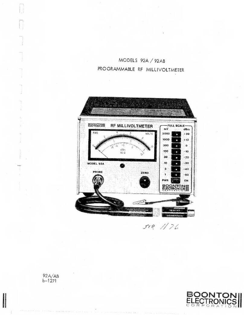
Boonton 4500A Installation and operating instructions

98404704A
1
BOONTON ELECTRONICS
A subsidiary of Noise/Com a Wireless Telecom Group Company
4400A/4500A MANUAL ADDENDUM
Applies to Instruction Manual Model 4500A RF Peak Power Meter /Analyzer, Model 4400A RF Peak Power
Meter, Part Number 98404700A, revised 09/97.
Effective for Control Software Revision 20010119 and later.
1. NEW FEATURES
1.1 Power vs Time Data Output Capability
Data Buffer Configuration. Each trace display of the 4400A/4500A Peak Power Meter is
derived from a 501-element data buffer. Each element is a measurement value for one pixel in
the display. The elements are numbered from zero through 500. The element zero lies on the left-
most vertical gridline; the element 500 lies on the right-most gridline and element 250 lies on the
center gridline.
Data Buffer Output. Data can be output for Channel 1, Channel 2, Channel Math, Reference 1
or Reference 2. The data is adjusted for Vertical Offset, calibration factors and averaging. If the
display Units are set to “Linear”, power will be in watts with 5 decimal digits of resolution. The
real number format is: (-d.ddddE!dd , -dd.dddE!dd or –ddd.ddE!dd where the positive sign is
omitted and the exponent is mod 3) watts. Negative power values indicate underflow of the
system “zero”. If the display units are set to “Log”, power will be in dBm (decibels relative to 1
milliwatt) with a resolution of !0.01 dB. Negative linear power values will return –70.00 dBm
excluding offsets if not clipped.
In the Pulse mode with Log units a clip level is applied which establishes a minimum power
level based on the sensor calibration data. This level will vary depending upon the sensor type
and offsets.
For Channel 1 or 2 in the Trigger View mode the data will be returned in volts with a resolution
of !0.01 volts.
GPIB Data Buffer Output. Data buffer contents can be read over the GPIB using the
TKFPDISP talk mode command. This is a permanent talk mode that remains in effect until
replaced by a different permanent talk mode. TKFPDISP should be followed by an index
argument in the range 0 to 500 inclusive that specifies the number of the first element of the data

98404704A
2
buffer to be sent. The total number of elements requested is specified by the BUFCOUNT
command. BUFCOUNT is followed by an argument in the range 1 to 501 inclusive.
After the TKFPDISP command and argument are sent, the first time the 4400A/4500A is
addressed to talk (MTA is sent), a string of comma delimited elements will be returned
beginning with the index value followed by BUFCOUNT measurement values as described
above.
Each successive time the power meter is addressed to talk the index value will be automatically
advanced by BUFCOUNT number of elements and a new string returned. If the incremented
pointers reach beyond the last element in the buffer the string is truncated and fewer than
BUFCOUNT values are returned. At least one index and one element is always returned.
Example: BUFCOUNT 10
TKFPDISP 0
[MTA] Returns 0, p0, p1, p2, p3, p4 … p9
[MTA] Returns 10, p10, p11, p12, p13 …p19
Example: BUFCOUNT 501
TKFPDISP 0
[MTA] Returns 0, p0, p1, p2 …….p500 (entire buffer)
[MTA] Returns 500, p500 (truncated to one element)
Example: BUFCOUNT 5
TKFPDISP 496
[MTA] Returns 496, p496, p497, p498, p499, p500
The source buffer is selected using the CH1, CH2, CHM, REF1 and REF2 commands. The units
are selected using LIN or LOG. TKFPDISP does not interrupt sampling and data collection
while sending data. For this reason buffer data will not remain stable during a transfer. If this
behavior is undesirable, issue the STOP command to stop data capture when appropriate.
Front Panel Data Buffer Output. Front panel data buffer output is controlled by the
Prgm>Trace Data> menu. An entire data buffer can be sent to a Floppy Disk file, the COM1
serial port or the LPT1 line printer. No index value is used. The delimiter separating data
elements can be selected to be a comma, LF (line-feed or NL), CR (carriage return) or ASCII
space. This is useful if the data file is to imported directly into a spreadsheet.
Prgm>Trace Data>Select A number, nn, 0 to 99 which specifies the filename
B4500Ann.TXT. Applies only to Disk output.
Prgm>Trace Data>Source Select the data buffer: CH1, CH2, CH Math, Ref1, Ref2

98404704A
3
Prgm>Trace Data>Destination Select the output device: LPT1, COM1 Disk
Prgm>Trace Data>Delimiter Select the data element delimiter: comma, LF, CR, Space
Prgm>Trace Data>Send Data Press to START data transfer from buffer to device.
GPIB Control of Front Panel Output Controls. In addition to the direct GPIB output via the
TKFPDISP and BUFCOUNT commands, the alternate device outputs can also be controlled
over the bus. The specific commands are given below.
FILENO Sets the filename B4500Ann.TXT for Disk output where nn is the argument of
FILENO. Valid range is 0 to 99.
BUFDELCO Set buffer delimiter to comma.
BUFDELLF Set buffer delimiter to linefeed (NL)
BUFDELCR Set buffer delimiter to carriage return
BUFDELSP Set buffer delimiter to space.
Note: The delimiters do not apply to data returned using TKFPDISP. They apply only to output
using DATASEND.
DATACOM1 Select COM1 serial port output.
DATADISK Select the floppy disk output with filename selected with FILENO
DATALPT1 Select the printer port LPT1 for output. Delimiter will affect printed format.
DATASOCH1 Select the Channel 1 buffer.
DATASOCH2 Select the Channel 2 buffer.
DATASOCHM Select the Channel Math buffer.
DATASORF1 Select the Reference 1 buffer.
DATASORF2 Select the Reference 2 buffer.
Note: These source selections do not apply to data returned by TKFPDISP. They apply only to
output using DATASEND.
DATASEND Action command which causes the data buffer to be sent to the selected output.
Unlike output to the GPIB data capture is interrupted during transfers to output ports and the
disk.

98404704A
4
1.2 Statistical Data Output Capability
The following data output capability is applicable only to the Model 4500A.
4500A Statistical Histogram GPIB Output.
The 4500A statistical histogram count array accumulated by running a CDF, 1-CDF or PDF
function is output in two arrays of 4096 values each.
1. The X-axis array consists of up to 4096 power values in watts or dBm as described
above. The bus commands LIN and LOG are used to set the units. The Channel 1
array is selected by the command SELDATTBL 6 and the Channel 2 array by
SELDATTBL 7. The array is returned by the talk mode command TK-TBLDAT n,
where n is the starting index number. The BUFCOUNT command followed by a
count argument of 1 to 4096 operates as described above for the TKFPDISP
command.
2. The Y-axis array consists of up to 4096 count values. The count value is the number
of times the power sample value has fallen within the bin located by the index
number. The power in watts or dBm for the center of each bin or index number is
given by the X-axis array above. The ratio of each bin count to the total sample count
is the probability of occurrence for that bin. The Channel 1 count array is selected by
the command SELDATTBL 8 and the Channel 2 count array by SELDATTBL 9. The
array is returned by the talk mode command TK-TBLDAT n, where n is the starting
index number. The BUFCOUNT command followed by a count argument of 1 to
4096 operates as described above for the TKFPDISP command.
4500A Front Panel Histogram Output. Front panel histogram output is controlled by the
Prgm>Trace Data> menu. An entire data buffer can be sent to a Floppy Disk file, the COM1
serial port or the LPT1 line printer. No index value is used. The delimiter separating data
elements can be selected to be a comma, LF (line-feed or NL), CR (carriage return) or ASCII
space. This is useful if the data file is to be imported directly into a spreadsheet.
For the Model 4500A, additional source choices will appear in the menu as follows:
Prgm>Trace Data>Source Select the data buffer: CH1, CH2, CH Math, Ref1, Ref2,Cal
Tbl 1,Cal Tbl 2,Histogram 1,Histogram2
Cal Tbl 1 and 2 are the x-axis power value arrays and Histogram 1 and 2 are the count arrays for
Channel 1 and 2 respectively. All other front panel controls and associated GPIB commands
operate as described above except that the SELDATTBL n, command is used instead of the data
source commands.

98404704A
5
1.3 Screen Saver
A screen saver feature has been added to increase CRT phosphor life in system applications. The
display will be dimmed after a specified time during which there is no front panel control
activity. The delay time in minutes is set in the Disp>Scrn Saver Delay menu window. The delay
can be varied from 1 to 240 minutes via the front panel keyboard, knob or increment /decrement
buttons. To disable the feature select the increment above 240 which is “infinite” or enter 241
minutes. The CRT display will then remain bright at all times.
The display when dimmed will be restored to full brightness by any front panel key or knob
operation. The delay/infinite setting is non-volatile and will be restored after power off/on. There
are no related bus commands for this feature.
1.4 New Auto-Measure function, EdgeDly
A new auto-measure function, number 15, Edge Delay, has been added to the TEXT display.
Edge delay shows the time delay between the left edge of the display window and the first
waveform edge of either slope. This allows the display window to be used as a mask to select or
exclude portions of a waveform. Trigger delay adjusts the position of the display window with
respect to the trigger. Edge Delay should be added as item 15 in Table 4-19. It appears as a
selection in the Meas > Param Meas > Param Top {Middle and Bottom} menus. The GPIB
PARAM___ commands will accept the value 15 as an argument and allow Edge Delay to be
selected remotely.
1.5 New GPIB Commands
Additions to Table 5-3 Mode 4400A/4500A Talk Mode Bus Mnemonics.
Code Arg Function
TKATEMP -- Returns a status flag and the sensor auto-cal temperature for both
channels. For the status flag 0 = valid, 1 = no sensor, 2 = no channel
card. The auto-cal temperatures are returned in tenths of a degree
Celsius (##.#). After returning data the instrument returns to the
previous Talk mode.
Format: status1, auto-cal temp1, status2, auto-cal temp2
Examples: send TKATEMP
read 0, 34.0, 0, 39.0 valid both channels
or read 0, 34.0, 1, -23.0 valid ch1; no sensor in ch2
or read 0, 34.0, 2, -23.0 valid ch1; no ch2 installed

98404704A
6
TKEJD -- For the currently selected measurement channel returns a status flag
and the time delay in seconds between the left edge of the display
window and the first waveform edge of either slope. Trigger delay can
be used to move the window with respect to the trigger to select or
exclude portions of a long string of pulses. This command works only
with TKAMEAS active. After returning data the instrument returns to
the previous Talk mode, normally TKAMEAS.
Examples: send TKAMEAS send only once
send TKEJD “send TKEJD read” may be repeated
read 1, 1.163e-7 valid edge delay in seconds
or read 0, 0 no valid result
TKMMODE -- Returns a measurement mode run/stop flag, mode identifier and units
flag. For the run/stop flag 0 = STOP, 1 = RUN. For the mode
identifier 0 = Pulse, 1 = CW, 2 = CDF, 3 = 1-CDF, 4 = PDF. For the
units flag 0 = log (dBm) and 1 = linear (watts). After returning data
the instrument returns to the previous Talk mode.
Examples: send TKMMODE
read 1, 0, 0 running in pulse mode with log units
or read 0, 3, 1 stopped in 1-CDF mode with linear
units
1.6 EOI Only Talk mode Terminator
In the Util > IEEE-488 > Bus Setup > Talk Term menu a new choice, EOI only, has been added.
This allows return strings to be terminated only by the EOI signal of the GPIB, simplifying setup
with controllers which use this as their default.
1.7 Reference Lines in Linear Units mode
Reference Lines and Reference Line Tracking now work in the Linear as well as Logarithmic
units modes. Reference line level readout is always in dBm.
2. CORRECTIONS
2.1 Sensor Temperature Readings
All previous versions and revisions of Model 4400/4500/4400A and 4500A report sensor
temperature approximately 10 degrees Celsius lower than the actual internal sensor temperature.
This characteristic has been of little consequence since only delta temperature values are used.

98404704A
7
For future developments it is desirable to use the actual internal sensor temperature. Effective
with this revision (20010119) all sensor temperatures are the actual internal temperature.
Compatibility with previous software revisions. The effect of this change is expected to be
minimal because delta temperature values are not affected. Some GPIB programs may use
absolute sensor temperature values and expect the old style values for correct operation. To
accommodate this situation, a new GPIB command OLD_TEMP# has been included in the new
revision. To use the old style temperatures, issue the GPIB command OLD-TEMP# in the
initialization part of the program. This will cause all sensor temperature values to appear as in
earlier revisions. The effect of this command is volatile and it must be re-issued after a power
off/on cycle.
2.2 Failure to resume in Statistical mode on power up (4500A only).
Some previous software revisions contain a bug that causes statistical measurements not to
resume correctly on power up. This occurs only when the instrument was powered down in one
of the statistical modes. Normal operation will resume if the menu selection or a GPIB measure
mode command is sent. This revision (20010119) corrects the error and under the above
conditions statistical measurements will resume automatically at power up.
2.3 Inability to use request for service (SRQ) on settled measurement in CW
mode with averaging > 1.
In all previous revisions in CW measurement mode with the SRQ mask set to 2, no service
request would be issued unless the Averaging was set to 1. This bug has been fixed in this
revision (20010119). Since CW is a continuous mode it is necessary to stop and start the
measurement in order to obtain repeated service requests with settled readings. Stopping the
continuous measurement resets the averaging system. After a restart and after the averaging time
has expired, the service request will be issued if the mask for settled measurement (2) is enabled.
The serial poll issued by the GPIB controller reads and resets the service request, but not the
settled measurement flag. To restore synchronization between the controller and the
measurement process, it is necessary to issue the STOP command. When the desired signal is
present at the power sensor input, issue the RUN command. When the selected averaging is
completed, the service request will again be made. This sequence can be repeated indefinitely.
Revised 20010126
This manual suits for next models
1
Table of contents
Other Boonton Measuring Instrument manuals
Boonton
Boonton 4541 User manual
Boonton
Boonton 92E User manual
Boonton
Boonton 4530 Series Use and care manual
Boonton
Boonton 92BD User manual

Boonton
Boonton 4210 User manual
Boonton
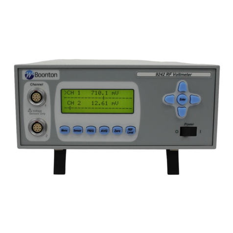
Boonton 9240 Series User manual
Boonton
Boonton 1121A User manual

Boonton
Boonton PMX40 User manual

Boonton
Boonton 92EA User manual

Boonton
Boonton 8201A User manual
Popular Measuring Instrument manuals by other brands

Apana
Apana PK1276-USB user guide
Endress+Hauser
Endress+Hauser SpectraSensors SS2100 Safety manual
Konica Minolta
Konica Minolta SKR 4000 user manual

Endress+Hauser
Endress+Hauser SpectraSensors OXY5500 Safety manual

Ushio
Ushio UIT-0 Series User's manual and troubleshooting guide
Savant
Savant SEM-2015 Quick reference guide
