Boonton PMX40 User manual

PMX40 RF Power Meter – INSTRUCTION MANUAL
INSTRUCTION MANUAL
PMX40
RF Power Meter
98408900A | Rev 20210115


PMX40 RF Power Meter – INSTRUCTION MANUAL
i
Revision 20210115
© Copyright 2021, by BOONTON Electronics, a subsidiary of the Wireless Telecom Group, Inc.
Parsippany, NJ, USA. All rights reserved.
P/N 98408900A
This manual covers the PMX40 RF Power Meter, serial numbers: 1001 and higher.
The PMX40 application software used in this product is licensed by Boonton Electronics, a subsidiary of
the Wireless Telecom Group, Inc.

PMX40 RF Power Meter – INSTRUCTION MANUAL
ii
SAFETY SUMMARY
The following general safety precautions must be observed during all phases of operation and
maintenance of this instrument. Failure to comply with these precautions or with specific warnings
elsewhere in this manual violates safety standards of design, manufacture, and intended use of the
instrument. Boonton Electronics assumes no liability for the customer’s failure to comply with these
requirements.
DO NOT OPERATE THE INSTRUMENT IN AN EXPLOSIVE ATMOSPHERE
Do not operate the instrument in the presence of flammable gases or fumes.
KEEP AWAY FROM LIVE CIRCUITS
Operating personnel must not remove instrument covers. Component replacement and internal
adjustments must be made by qualified maintenance personnel. Do not replace components with the
power cable connected. Under certain conditions dangerous voltages may exist even though the power
cable was removed, therefore; always disconnect power and discharge circuits before touching them.
DO NOT SERVICE OR ADJUST ALONE
Do not attempt internal service or adjustment unless another person, capable of rendering first aid and
resuscitation, is present.
DO NOT SUBSTITUTE PARTS OR MODIFY INSTRUMENT
Do not install substitute parts or perform any unauthorized modifications on the instrument. Return the
instrument to Boonton Electronics for repair to ensure that the safety features are maintained.

PMX40 RF Power Meter – INSTRUCTION MANUAL
iii
SAFETY SYMBOLS
This safety requirement symbol has been adopted by the International Electro-technical
Commission, Document 66 (Central Office) 3, Paragraph 5.3, which directs that an
instrument be so labeled if, for the correct use of the instrument, it is necessary to refer
to the instruction manual. In this case it is recommended that reference be made to the
instruction manual when connecting the instrument to the signal source and USB host.
The CAUTION symbol denotes a hazard. It calls attention to an operational procedure,
practice, or instruction that, if not followed, could result in damage to or destruction of
part or all of the instrument and accessories. Do not proceed beyond a CAUTION symbol
until its conditions are fully understood and met.
The NOTE symbol is used to mark information that should be read. This information can
be very useful to the operator in dealing with the subjects covered in this section.
The HINT symbol is used to identify additional comments that are outside of the normal
format of the manual and provide users additional information about the subject.

PMX40 RF Power Meter – INSTRUCTION MANUAL
Contents
1 General Information ..........................................................................................................................1-1
1.1 Organization...............................................................................................................................1-1
1.2 Description .................................................................................................................................1-2
1.3 Features .....................................................................................................................................1-2
1.4 Accessories.................................................................................................................................1-2
1.5 Optional Configurations.............................................................................................................1-2
1.6 Specifications .............................................................................................................................1-2
2 Installation .........................................................................................................................................2-1
2.1 Unpacking & Repacking .............................................................................................................2-1
2.2 Power Requirements .................................................................................................................2-2
2.3 Connections ...............................................................................................................................2-2
2.4 Preliminary Check ......................................................................................................................2-3
3 Getting Started...................................................................................................................................3-1
3.1 Organization...............................................................................................................................3-1
3.2 Operating Controls, Indicators, and Connections......................................................................3-1
3.3 Touch Screen Display .................................................................................................................3-4
3.4 Initialization................................................................................................................................3-6
3.5 Making Measurements ..............................................................................................................3-8
3.5.1 Continuous Mode...............................................................................................................3-8
3.5.2 Pulse Mode ........................................................................................................................3-9
3.5.3 Statistical Mode ...............................................................................................................3-10
4 Operation ...........................................................................................................................................4-1
4.1 Manual Operation......................................................................................................................4-1
4.2 Control Menus ...........................................................................................................................4-1
4.3 Parameter Data Entry and Selection..........................................................................................4-2
4.3.1 Numerical Data Entry.........................................................................................................4-2
4.3.2 Parameter Pick-List Selection.............................................................................................4-2
4.4 Menu Reference.........................................................................................................................4-3
4.4.1 Main Menu.........................................................................................................................4-3
4.4.2 MAINMeasure ................................................................................................................4-3
4.4.3 MAINDisplay...................................................................................................................4-4
4.4.4 MAINStat. Mode ............................................................................................................4-4
4.4.5 MAINChannel .................................................................................................................4-5
4.4.6 MAINTime ......................................................................................................................4-8

PMX40 RF Power Meter – INSTRUCTION MANUAL
4.4.7 MAINTrigger...................................................................................................................4-8
4.4.8 MAINMarkers.................................................................................................................4-9
4.4.9 MAINPulse Def .............................................................................................................4-10
4.4.10 MAINSystem.................................................................................................................4-11
4.4.11 MAINSystemSensor Data .........................................................................................4-11
4.4.12 MAINSystemI/O ConfigLAN..................................................................................4-12
4.4.13 MAINSystemTest Source..........................................................................................4-12
4.4.14 MAINSystemExit.......................................................................................................4-13
4.4.15 MAINSystemReports ................................................................................................4-13
5 Application Notes...............................................................................................................................5-1
5.1 Introduction to Pulse Measurements........................................................................................5-1
5.1.1 ...................................................................................................................................................5-1
5.1.2 Diode Detection .................................................................................................................5-3
5.2 Pulse Definitions ........................................................................................................................5-4
5.2.1 Standard IEEE Pulse............................................................................................................5-5
5.3 Automatic Measurements .........................................................................................................5-6
5.3.1 Automatic Measurement Criteria ......................................................................................5-6
5.3.2 Automatic Measurement Terms........................................................................................5-6
5.3.3 Automatic Measurement Sequence ..................................................................................5-7
5.3.4 Average Power Over an Interval ......................................................................................5-10
5.4 Statistical Mode Automatic Measurements ............................................................................5-11
5.5 Measurement Accuracy ...........................................................................................................5-13
6 Maintenance ......................................................................................................................................6-1
6.1 Safety .........................................................................................................................................6-1
6.2 Cleaning......................................................................................................................................6-1
6.3 Inspection...................................................................................................................................6-1
6.4 Lithium Battery ..........................................................................................................................6-2
6.5 Software Upgrade ......................................................................................................................6-2
Appendix A - Warranty and Repair Policy................................................................................ APPENDIX A-1
Appendix B - End User License Agreement............................................................................... APPENDIXB-1


PMX40 RF Power Meter – INSTRUCTION MANUAL
1-1
1General Information
This instruction manual provides you with the information you need to install, operate, and maintain
the
Boonton PMX40 RF Power Meter. Section 1 is an introduction to the manual and the instrument.
1.1 Organization
The manual is organized into five sections and two Appendices, as follows:
Section 1 - General Information presents summary descriptions of the instrument and its principal
features, accessories, and options.
Section 2 - Installation provides instructions for unpacking the instrument, setting it up for
operation, connecting power and signal cables, and initial power-up.
Section 3 - Getting Started describes the controls and indicators and the initialization of operating
parameters. Several practice exercises are provided to familiarize yourself with essential setup and
control procedures.
Section 4 - Operation describes the display menus and procedures for operating the instrument
locally from the front panel.
Section 5 - Application Notes provides supplementary information about PMX40 and sensor operation,
advanced features, pulse measurement information, and measurement accuracy.
Appendix A - Warranty and Repair Policy states the policies governing the return and replacement of
modules and instruments during and after the warranty period.
Appendix B - End User License Agreements

PMX40 RF Power Meter – INSTRUCTION MANUAL
1-2
1.2 Description
The PMX40 RF Power Meter provides design engineers and technicians the utility of traditional
benchtop instruments, the flexibility and performance of modern USB RF power sensors, and the
simplicity of a multi-touch display built with Boonton award-winning technology.
As a benchtop meter, the PMX40 provides a standalone solution for capturing, displaying, and analyzing
peak and average RF power in both the time and statistical domains through an intuitive, touch screen
display.
The PMX40 RF Power Meter utilizes up to four Boonton USB RF power sensors with industry-leading
performance and capabilities either independently or for synchronized multi-channel measurements of
CW, modulated, and pulsed signals.
Providing the ultimate flexibility, the PMX40 sensors can be disconnected and independently used as
standalone instruments.
1.3 Features
See PMX40 Datasheet for a brief description of key features.
1.4 Accessories
See PMX40 Datasheet for a complete list of accessories.
1.5 Optional Configurations
See PMX40 Datasheet for a complete list of optional configurations.
1.6 Specifications
See PMX40 Datasheet for the latest specifications.

PMX40 RF Power Meter – INSTRUCTION MANUAL
2-1
2Installation
This section contains unpacking and repacking instructions, power requirements, connection
descriptions, and preliminary checkout procedures.
2.1 Unpacking & Repacking
The PMX40 RF Power Meter is shipped complete and is ready to use upon receipt. Figure 2-1 shows you
the various pieces included in the packaging and the order in which they are loaded into the container.
Actual details may vary from the illustration.
Note Save the packing material and container to ship the instrument, if necessary. If the
original materials (or suitable substitute) are not available, contact Boonton Electronics
to purchase replacements. Store materials in a dry environment.
Figure 2-1. Packaging Diagram
Table 2-1. PMX40 RF Power Meter Packing List
PMX40 RF Power Meter
Line Cord
Information Card (describes where to download the latest manual, software, utilities)
For benchtop use, choose a clear, uncluttered area. Ensure that there is at least 2" of clearance at the
fan air intake on the rear panel and the exhaust vents on the side panels. Pull-down feet are located on

PMX40 RF Power Meter – INSTRUCTION MANUAL
2-2
the bottom of the instrument. Rack mounting instructions are provided with the optional rack mount
kit.
2.2 Power Requirements
The PMX40 is equipped with a switching power supply that provides automatic operation from a 90 to
264 VAC, 47 to 63 Hz single-phase, AC power source. Maximum power consumption is 70 VA. Connect
the power cord supplied with the instrument to the power receptacle on the rear panel. See Figure 3-2.
Caution Before connecting the instrument to the power source, make certain that a 1.0-ampere
time delay fuse (type T) is installed in the fuse holder on the rear panel.
Before removing the instrument cover for any reason, position the input module power
switch to off (0 = OFF; 1 = ON) and disconnect the power cord.
2.3 Connections
Sensor(s) Compatible sensors can be connected to any of the USB ports on the front or rear panel.
However, the base PMX40 model only permits two sensors to be active at any one time.
With the PMX40-4CH option, four sensors can be active at any one time. Sensors
become active when plugged into a USB port or immediately if already plugged in when
the PMX40 powers up.
Trigger Most triggered applications can use the RF signal applied to the sensors for triggering.
For measurements requiring external triggering, connect the external trigger signal to
the Trig In BNC connector on the rear panel and connect a Sync cable from the Sync
connector on the meter to the Multi I/O port on the sensor.
Note The Sync cable must be connected to the Sync port corresponding to the USB port for
the sensor Channel in use.
Remote If the instrument is to be operated remotely using the GPIB (IEEE-488) bus, connect the
instrument to the bus using the rear panel GPIB connector and appropriate cable. For
Ethernet control, connect to the rear panel LAN connector. In most cases, it will be
necessary to configure the interface using the SystemI/OConfig menus.

PMX40 RF Power Meter – INSTRUCTION MANUAL
2-3
2.4 Preliminary Check
The following preliminary check verifies that the instrument is operational and has the correct software
installed. It should be performed before the instrument is placed into service. To perform the
preliminary check, proceed as follows:
1. Press the lower half (marked "0") of the power switch in the center of the power module on the
rear panel.
2. Connect the AC (mains) power cord to a suitable AC power source; 90 to 264 VAC, 47 to 63 Hz.
The power supply will automatically adjust to voltages within this range.
3. Press the upper half (marked "1") of the power switch in the center of the power module on the
rear panel, it will enter standby mode.
4. Press the ON/STBY key (marked with the international 0/1 on/standby symbol) on the front
panel to turn the instrument on. The cooling fan and display backlight should turn on.
5. A bootup screen should appear that shows the boot status. After a self-check, the instrument
will execute the application program. There will be some temporary dialogs indicating application
initialization and channel updating. After several moments, a screen similar to Figure 2-2 should be
displayed.
Figure 2-2. Typical Power-On Display
PMX40 RF Power Meter – INSTRUCTION MANUAL
2-4
Note The base PMX40 model only permits two sensors to be active at any one time. With the
PMX40-4CH option, four sensors can be active at any one time.
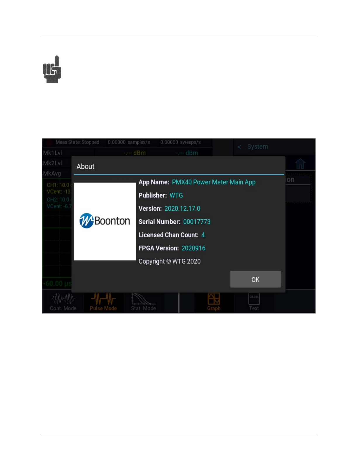
6. On the front panel, press the key to bring up the on-screen menu. From the Main menu, use
the touch screen or the ◄,►,▲, ▼, and keys on the front panel to browse to
SystemReportsConfiguration and select Show. A display similar to Figure 2-3 should appear.
Figure 2-3. System > Configuration Report Display
7. Follow the steps in Section 3.4 to initialize the instrument.

PMX40 RF Power Meter – INSTRUCTION MANUAL
3-1
3Getting Started
This chapter will introduce the user to the PMX40 RF Power Meter. The chapter will identify objects on
the front and rear panels, identify display organization, list the configuration of the instrument after
initializing, and provide practice exercises for front panel operation. For additional information, see
Section 4 "Operation."
3.1 Organization
Subsection 3.2 Operating Controls, Indicators, and Connections identifies the control features and
connections on the front and rear panels.
Subsection 3.3 Touch Screen Display describes the data fields in the standard (graphic mode) display.
Subsection 3.4 Initialization explains how to turn the instrument on for the first time, connect a sensor,
set the instrument up for operation, and initialize it to a known state. See Table 3-3 for initialized
parameters and their values.
Subsection 3.5 Making Measurements describes the different measurement modes of the PMX40.
3.2 Operating Controls, Indicators, and Connections
Figures 3-1 and 3-2 illustrate the controls, indicators, and connectors on the front and rear panels,
respectively, of the standard instrument. Refer to Table 3-1 for a description of each of the illustrated
items. The function and operation of all controls, indicators, and connectors are the same on the
standard and optional models.
Figure 3-1. PMX40 RF Power Meter - Front Panel
1
2
3
4
5
6
7
8
9

PMX40 RF Power Meter – INSTRUCTION MANUAL
3-2
Table 3-1. Operating Controls, Indicators, and Connections
Reference #
Front Rear Nomenclature Function
1 1 Sensor Inputs Four sensor inputs are located on the front and rear panels of
the instrument. These are standard USB 2.0 Type A receptacles
designed to accept only Boonton power sensors or standard
USB keyboards, mice, and flash drives.
2 2 Trigger Inputs Four sensor trigger inputs are located on the front and rear
panels of the instrument. These are standard SMB receptacles
designed to accept only Boonton power sensor trigger cables.
Caution Do not attempt to connect anything other than
Boonton power sensors and trigger cables!
3 3 Test Source The output of the built-in 50 MHz programmable test source is
available from a Type-N connector located on the front, or
optionally on the rear panel of the instrument. This test source
is used to verify basic performance of sensors used with the
PMX40.
4 Display Screen Color touch screen display for the measurement and trigger
channels, screen menus, status messages, text reports, and help
screens.
5 Key Favorites key. (This function is not fully implemented at this
time). Enables the user to setup a customized menu to allow
grouping frequently used menu items into one convenient
menu.
6 Key Store image key saves a screen image of the meter to local
storage. The images can be copied to an external USB storage
device.
7 ◄and ►Keys Used to assist navigating between items on the display and
in the menus. Unless the user is in digit editing numeric entry
mode.
7 ▲and ▼Keys Used for incrementing or decrementing numeric parameters, or
scrolling through multi-line or multi-page displays.
8 Key Selects an on-screen item or menu and completes a numeric or
picklist entry.
9 On/Standby Key Toggles the instrument between “on” (fully powered) and
“standby” (off, except for certain low-power internal circuits)
modes. Entering standby mode will perform a save of the

PMX40 RF Power Meter – INSTRUCTION MANUAL
3-3
current instrument state before shutdown. Pressing and holding
the On/Standby key for several seconds will force standby mode
if the instrument has become non-responsive. In this case, no
context save is performed.
10 Cooling Fan Cooling air intake
11 GPIB 24-pin GPIB (IEEE-488) connector for connecting the power
meter to the remote control General Purpose Instrument Bus.
GPIB parameters can be configured through the menu.
12 AC Line Input A multi-function power input module is used to house the AC
line input, main power switch, and safety fuse. The module
accepts a standard AC line cord, included with the power meter.
The power switch is used to shut off main instrument power.
The safety fuse may also be accessed once the line cord is
removed. The instrument’s power supply accepts 90 to
264 VAC, so no line voltage selection switch is necessary.
Caution Replace fuse only with specified type and rating:
1.0A-T (time delay type), 250 VAC.
13 HDMI HDMI receptacle for connecting an external monitor to mirror
front panel display. The image resolution will be 800 x 480 and
will be stretched to fit the external full display size.
14 LAN Ethernet LAN connector for remote control and firmware updates. Allows
DHCP or fixed (IP / Subnet) setting mode. LAN parameters can
be configured through the menu.
15 Trig In BNC input for connecting an external trigger signal to the power
meter. Voltage range is ±5 volts, but the input impedance is
1 Megohm to allow use of common 10x oscilloscope probe for a
±50 volt input range.
16 Multi I/O BNC input/output for flexible use. May serve as a status or
alarm output, signal level monitor, or settable voltage source.

PMX40 RF Power Meter – INSTRUCTION MANUAL
3-4
Figure 3-2. PMX40 RF Power Meter - Rear Panel
3.3 Touch Screen Display
The PMX40 RF Power Meter can be completely controlled through the touch screen display and by use
of the front panel buttons. Table 3-2 describes the different areas of the display layout of the PMX40 RF
Power Meter. Figure 3-3 shows the Graph Display mode of the instrument using the Pulse Measure
mode with a menu exposed. Figure 3-4 shows the same measure mode with the menus hidden. The Text
Display mode of the instrument provides a table view of measured parameters. Parameters depend on
the Measure mode selected. See Section 4.4 for more information on the display format.
Figure 3-3. PMX40 Graph Display Using Pulse Measure Mode With Menus Exposed
2
9
1
10
4
3
5
8
6
7
11
13
14
3
15
16
1
2
12
10

PMX40 RF Power Meter – INSTRUCTION MANUAL
3-5
Table 3-2. Touch Screen Display Fields
Reference # Field Name Description
1 Status Bar Indicates the measurement acquisition status of the unit. In
Pulse mode, the sample rate and number of sweeps per second
are also shown. In Statistical mode, it indicates the gating
setting in use, run time, and number of points.
2 Parameters Displays a table of measurements for each channel that is
enabled on the meter. In Pulse and Continuous mode,
measurements indicated are for power levels at each marker
and the average power between the markers. For Statistical
mode, the measurements are Average power, Maximum power,
and Peak-to-Average Ratio or Crest Factor.
3 Channel Status This area indicates which channels are ON and their individual
scale and vertical center.
Note The base PMX40 model only permits two sensors to
be active at any one time. With the PMX40-4CH
option, four sensors can be active at any one time.
4 Main Display This area will show a plot when in Graph Display mode or a
table of parameters when in Text Display mode for the
measurement mode selected
5 Menu Bar Select to show and to hide the on-screen menus.
6 Menu Path Used to navigate the menu structure. Shows the menu that will
be displayed when selected.
7 Current Menu/Home Displays the name of the current menu and provides a home
shortcut to the top-level Main menu. When in the Main or top-
level menu, this field is not available.
8 Horizontal Scale For Pulse and Continuous mode, indicates the time per division
for the waveform display. In Statistical mode, the horizontal
scale for the CCDF graph is in dBr (dB relative).
9 Measure Mode Indicates and allows selection of the current Measurement
mode. Modes available are Continuous, Pulse, and Statistical.
10 Display Mode Indicates and allows selection of the current Display mode in
use. Modes available are Graph and Text.
Hint The Graph Display mode for Continuous Measure mode
will be a flat trace. It is best to use Text Display mode
for continuous signal measurements.

PMX40 RF Power Meter – INSTRUCTION MANUAL
3-6
Figure 3-4. PMX40 Graph Display Using Pulse Measure Mode With Menus Hidden
3.4 Initialization
The steps shown here will initialize the PMX40 meter and prepare it for normal operations. Step 3
should only be performed when you wish to set the meter operations to a known state. This is typically
done when you first power on the instrument or at the start of a new test.
STEP PROCEDURE
1. If the main power is off, press the power switch located on the rear panel. See Figure 3-2. Press
the On/Standby key. See Figure 3-1. After a self-check, the instrument will execute the
application program. There will be some momentary dialogs indicating application initialization
and channel updating. After the last dialog the main screen will be on the display.
Caution When selecting a sensor for an exercise or a measurement, be sure you know
the power range of the sensor. Operation beyond the specified upper power
limit may result in a permanent change of characteristics or burnout.
2. Connect the sensor USB cable to the Channel 1 input on the front or rear of the instrument.
When the sensor is connected or disconnected, the instrument will momentarily show a channel
update dialog.
Table of contents
Other Boonton Measuring Instrument manuals

Boonton
Boonton 92EA User manual

Boonton
Boonton 92BD User manual

Boonton
Boonton 4500A Installation and operating instructions

Boonton
Boonton 4210 User manual

Boonton
Boonton 1121A User manual

Boonton
Boonton 9240 Series User manual

Boonton
Boonton 4530 Series Use and care manual

Boonton
Boonton 8201A User manual

Boonton
Boonton 4541 User manual

Boonton
Boonton 92E User manual


