Boonton 75D User manual

DIRECT
CAPACITANCE
BRIDGE,
MODEL
75D
(1
MHz)
INSTRUCTION
MANUAL
75D
b-370
BOONTON
ELECTRONICS
GOfRROfR/ATI
O'
Ni
TEL.
201
-887-5110
TWX:
710-986-8241
ROUTE
287
AT
SMITH
ROAD
PARSIPPANY.
N
J
—
07054

TABLE
OF
CONTENTS
CHAPTER
PAGE
I
GENERAL
DESCRIPTION
1
1
.1
General
1
1
.2
Equipment
Description
1
1
.3
Optional
Accessories
2
1
A
Technical
Characteristics
3
1
.5
Theory
of
Operation
7
II
INSTALLATION
14
2
0
1
Unpacking
and
Inspect!
on
14
2.1.1
Unpacking
14
2.1.2
Inspection
14
2.2
Packing
for
Reshipment
14
2.3
Power
Connections
14
2.4
Rack
Installation
15
III
OPERATION
17
3.1
General
17
PART
1
.
Preliminary
Operating
Instructions
3.2
Controls
and
Indicators
17
3.3
Starting
Procedure
21
3.4
Initial
Switch
and
Control
Settings
22
3.5
Zero-Balancing
the
Bridge
22
3.5.1
Test
Level
Control
23
3.5.2
Gain
Control
23
3.5.3
Bias
Arrangements
23
PART
2.
Amplitude-Mode
Measurements
3.6
General
24
3.6.1
C,
G,
Rp,
Q
and
D
Measurements
24
3.6.2
L,
G,
Rp,
Q
and
D
Measurements
25
PART
3.
Phase-Mode
Measurements
3.7
General
29
3.7.1
Capacitance
Measurements
Only
29
3.7.2
Inductance
Measurements
Only
30
75
D
b-370

PART
4.
Single-Limit
Testing
3.8
General
32
3.8.1
Single-Limit
Capacitance
Test
32
3.8.2
Single-Limit
Inductance
Test
33
PART
5.
Differential
Measurements
3.9
General
35
3.9.1
Differential
Capacitance
in
Amplitude
Mode
35
3.9.2
Capacitor
Temperature
Coefficient,
Amplitude
Mode
36
3.9.3
Differential
Inductance
in
Amplitude
Mode
37
3.9.4
Differential
Capacitance
in
Phase
Mode
38
3.9.5
Capacitor
Temperature
Coefficient
in
Phase
Mode
39
3.9.6
Differential
Inductance
in
Phase
Mode
41
IV
MAINTENANCE
4.1
General
44
4.2
Preventive
Maintenance
44
4.3
Corrective
Maintenance
44
PART
1
.
Equipment
Performance
Tests
4.4
Using
the
Equipment
Performance
Checklist
44
4.5
Test
Equipment
and
Accessories
Required
45
PART
2.
Troubleshooting
4.6
General
62
PART
3.
Alignment
and
Calibration
4.7
General
62
4.8
Null
Indicator
Alignment
62
4.9
Oscillator-Detector
Alignment
63
4.10
Bridge
Capacitance
Alignment
and
Calibration
65
4.11
Bridge
Conductance
Calibration
Check
70
PART
4.
Disassembly
and
Reassembly
4.12
Cabinet
73
4.13
Bridge
73
75D
b-370

LIST
OF
ILLUSTRATIONS
FIGURE
PAGE
1
Direct
Capacitance
Bridge,
Model
75D
A
2
Basic
Bridge
Configuration
8
3
Model
75D
Block
Diagram
10
4
Simplified
Schematic,
Phase
Detector
11
5.
Basic
Bridge
Equations
13
6
Controls
and
Indicators
16
7
Conductance
Correction
Curve,
MULTIPLY
C
XI
Range
26
8.
Conductance
Correction
Curve,
DIVIDE
G/MULTIPLY
R
XI
27
9.
Capacitor
Nomograph
43
10
Voltage-Resistance
Test
Chart
82
11
Oscillator-Detector
Assembly
83
12
Bridge
Assembly
(With
Cover
Removed)
84
TABLES
TABLE
NO.
PAGE
1
Optional
Accessories
2
2
Technical
Characteristics
3
3
Controls
and
Indicators
17
4
Initial
Switch
and
Control
Settings
22
5
Equipment
Performance
Checklist
45
6
Troubleshooting
Chart
74
TABLE
OF
REPLACEABLE
PARTS
Following
Page
84
Schematics
Oscillator-Detector
Test
Points
and
Waveforms
Endfold
Endfold

CONDUCTANCE
CAPACITANCE
pr
DIRECT
CAPACITANCE
BRIDGE
HODCt
KO
tfSf
fMQ
MIU
jfismaE
I
.
1
ICATOR
1
L
j
f
DM
rt*T
iNT
ixr
U
AOJUS7
•
-
rjp
Figure
1
„
Direct
Capacitance
Bridge,
Model
75D,
(1
MHz)
75D
b-370
A

CHAPTER
I
GENERAL
DESCRIPTION
1
.1
GENERAL.
The
Direct
Capacitance
Bridge,
Model
75D,
(1
MHz)
is
a
self-
contained
test
instrument
(
Figure
1
)
designed
for
use
as
a
precision
laboratory
bridge
to
measure
values
of
capacitors,
inductors,
and
semiconductor
devices,
or
to
perform
single-limit
sorting
tests
of
capacitive
or
inductive
specimens,,
The
instrument
provides
direct
(3-terminal
)
readings
of
parallel
capacitance
(C),
effective
parallel
conductance
(G),
and
equivalent
parallel
resistance
(Rp).
Parallel
inductance
(L)
is
measured
in
terms
of
equivalent
capacitance,
and
dissipation
(D)
or
Q
are
readily
determined
by
a
simple
computation.
The
Model
75D
is
largely
insensitive
to
capacitdnce
from
either
side
of
the
specimen
to
ground
and
provides
accurate
readings
even
in
the
presence
of
relatively
large
stray
capacitance,,
Thus,
the
direct
capacitance
of
specimens
is
precisely
measured,
and
a
remote
test
jig
or
coaxial
cables
may
be
used
to
connect
specimens
without
introducing
errors
due
to
jig
capacitance
or
cable
capacitance.
Test
specimens
may
be
biased
directly
by
the
internal
dc
supply,
or
an
external
bias
voltage
may
be
applied
through
terminals
on
the
front
panel.
External
capacitance
standards
also
may
be
connected
at
the
front
panel
to
check
calibration
or
to
perform
comparison
or
differential
measurements.
Other
typical
uses
of
the
Model
75D
are
as
follows:
Measurement
of
the
capacitance
of
semiconductors
Measurement
of
the
capacitance
of
varactors
Test
or
measurement
of
capacitance
elements
of
microcircuit
chips
Measurement
of
the
temperature
coefficient
of
capacitors.
Measurement
of
stray
circuit
capacitance.
Measurement
of
stray
circuit
capacitance
In
addition,
the
Model
75D
is
used
for
single-limit
and
dual-limit
testing
and
sorting
operations
of
capacitors,
inductors,
and
semiconductor
devices
during
production
testing,
incoming
inspection,
quality
assurance,
and
similar
applications.
1
.2
EQUIPMENT
DESCRIPTION
„
The
M
odel
75D
contains,
in
one
cabinet,
abridge,
signal
source,
null
detector,
power
supply
and
bias
supply.
All
operating
controls
and
indicators
are
mounted
on
the
front
panel.
If
required,
the
Model
75D
may
be
removed
from
the
cabinet
and
installed
in
a
standard
19-inch
rack.
A
bracket
is
installed
on
the
rear
panel
to
secure
the
instrument's
ac
power
cable,
and
a
terminal
shield
is
provided
for
the
TEST
binding
posts.
This
serves
to
shield
the
binding
posts
from
hand-capacitance
or
stray-capacitance
effects
when
the
REMOTE
coaxial
terminals
are
used
to
connect
specimens
of
standards.
75D
b-370
1

1.3
OPTIONAL
ACCESSORIES.
The
accessories
described
in
the
following
table
are
available
for
use
with
the
Model
75D
to
increase
its
versatility.
For
additional
information,
call
on
either
your
nearest
sales
engineering
representative
or
the
Boonton
Electronics
Corporation.
Table
I.
Optional
Accessories
ACCESSORY
FUNCTION
Capacitance
Standards,
Model
CS
Range
Extender,
Model
77-2A
Range
Divider,
Model
77-4A
Ground
Plane
Adapter,
Model
75-6A
Dust
Covers
Transfer
capacitance
standards
calibrated
against
NBS-
certified
reference
standards.
Used
to
calibrate
or
check
the
accuracy
of
3-terminal
capacitance
bridges
and
to
provide
high-resolution
comparison
measurements.
Available
in
any
value
from
0.01
to
1000-pF
at
0.1%
accuracy.
Designed
for
operation
from
1
kHz
to
1
MHz.
Extends
the
capacitance
range
of
the
Model
75D
to
0.1
pF,
conductance
range
to
1
mho,
resistance
range
to
1
ohm,
and
inductance
range
to
0.25
pH.
Divides
Model
75D
capacitance
readings
by
a
fixed
factor
of
10
and
permits
measurements
down
to
O.OO0O1
pF.
Can
be
used
with
the
Model
75D
to
perform
(if
required)
grounded
(2-terminal)
measurements
or
tests.
When
installed
on
the
TEST
binding
posts,
the
adapter
provides
a
ground
plane
that
enables
the
(3-terminal)
Model
75D
to
simulate
2-terminal
(grounded)
measurements
or
tests.
Perforated
metallic
covers.
Replace
cabinet
when
the
Model
75D
is
rack¬
mounted.
75D
b-370
2

1
A
TECHNICAL
CHARACTERISTICS,,
The
technical
characteristics
of
the
Model
75D
are
shown
in
the
following
table:
TABLE
2
Technical
Characteristics
a.
Capacitance
Measurement
Capacitance
Range:
0
to
1000
pF
Capacitance
Resolution
and
Accuracy:
Resolution
Accuracy
MULTIPLY
C
Setting
Capacitance
Range
(pF)
Phase
Mode
(pF)
Amplitude
Mode(pF)
Phase
Mode
Amplitude
Mode
1
.0
0
to
1000
0.2
0.2
+(0.25
+
1°-)%
+
0.5pF*
Q
+0.25%+(1000/R
D
+0.5)pF
—
P
0.1
0
to
100
0.02
0.02
+(0.25
+-L)%
+
0.05pF
w
+0.25%+(1000/Rp+0.05)pF
0.01
0
to
10
0.002
0.002
+(0.25
+-jL)%
+
0.005pF
+
0.25%+(l
000/R
p
+0.005)pF
0.001
0
to
1
0.0002
0.0005
+(0.25+—)%+0.001pF
Q
±0.25%+(l
000/Rp+0.001
)pF
0.0001
0
to
0.1
0.00005
0.0005
+(2+-J°)%
+0.00005pF
±2%
+(1000/Rp+0.0005)pF
Where
Rp
is
the
equivalent
parallel
resistance
of
the
specimen
in
ohms.
*
Q
must
be
10
or
greater.
75D
b-370
3

Table
2.
Technical
Characteristics
(cont'd.)
bo
Inductance
Measurement
Inductance
Range:
25
fjH
to
25
mH.
Inductance
Accuracy:
multiply
c
Setting
Accuracy
Inductance
Range
Phase
Mode
Amplitude
Mode
1.0
25
pH
to
250
M
H
+
(0.25+-!^
+
2L)%*
+
(0.25
+
2L
+
4
°
00L
)
%
R
P
0.1
250
pH
to
2.5mH
+
(0.25+-^-+-^%
±(0.25+
L
+
4000L
)%
10
R
p
0.01
2.5mH
to
25mH
±(0
-
2
5+
l
+
-S0-
)%
+
(0.25+
L
+
4000L
)%
50
R
p
Where
L
is
the
inductance
of
the
specimen
in
millihenries.
Rp
is
the
equivalent
parallel
resistance
of
the
specimen
in
ohms.
c.
Conductance
Measurement
Conductance
Range
(amplitude
mode
only):
0
to
1000
pmhos
Conductance
Resolution
and
Accuracy:
DIVIDE
G
Setting
Conductance
Range
Resolution
Accuracy
1
0
to
1000
pmhos
5
pjnhos
+
(10
+
-^^)%
+
10
pmhos
10
0
to
100
pmhos
0.5
pmho
±(
5
+
^)%+
1
Mmh
°
100
0
to
10
pmhos
0.05
pmho
±(
5
+
36o
)%
+
o
j
Mmho
1000
0
to
1
pmho
0.01
pmho
+
(5+—)%
+
0.01
pmho
500
75D
b-370
4
Table
2„
Technical
Characteristics
(cont'd.)
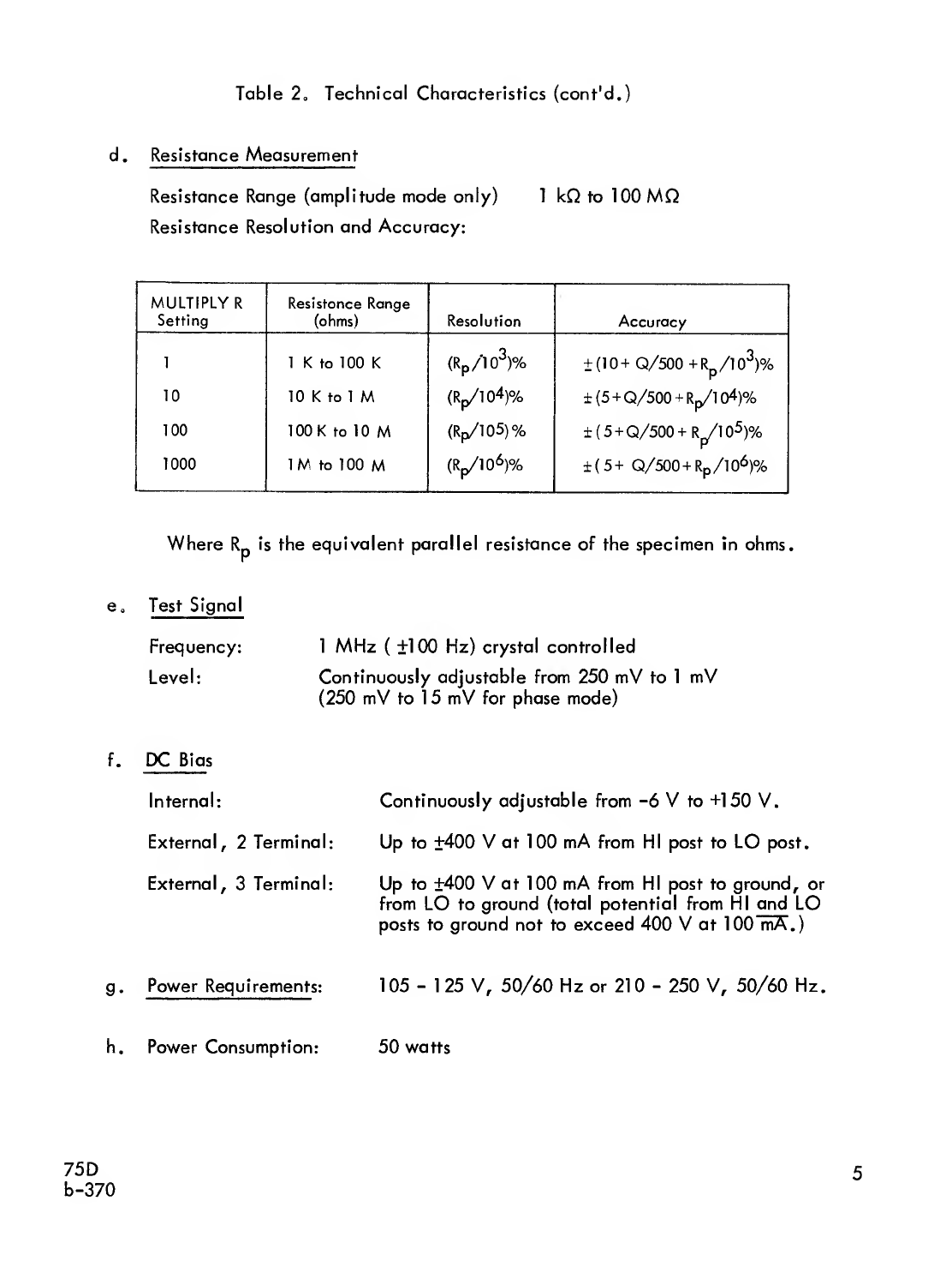
d.
Resistance
Measurement
Resistance
Range
(amplitude
mode
only)
1
kQ
to
100
MQ
Resistance
Resolution
and
Accuracy:
MULTIPLY
R
Setting
Resistance
Range
(ohms)
Resolution
Accuracy
1
1
K
to
100
K
(Rp/10
3
)%
+
(10+
Q/500
+Rp/10
3
)%
10
10
K
to
1
M
(Rp/l0
4
)%
±
(5
+
Q/500
+
Rp/l
04)%
100
100
K
to
10
M
(Rp/1
0
5)
%
±
(5
+
Q/500
+
R^l
0
5
)%
1000
1
M
to
100
M
(Rp/10
6
)%
±(5+
Q/500
+
R
p
/
10
6
)%
Where
R
is
the
equivalent
parallel
resistance
of
the
specimen
in
ohms.
r
e„
Test
Signal
Frequency:
1
MHz
(
+100
Hz)
crystal
controlled
Level:
Continuously
adjustable
from
250
mV
to
1
mV
(250
mV
to
15
mV
for
phase
mode)
f.
D
C
Bias
Internal:
Continuously
adjustable
from
-6
V
to
+150
V.
External,
2
Terminal:
Up
to
+400
V
at
100
mA
from
HI
post
to
LO
post.
External,
3
Terminal:
Up
to
±400
V
at
100
mA
from
HI
post
to
ground,
or
from
LO
to
ground
(total
potential
from
HI
and
LO
posts
to
ground
not
to
exceed
400
V
at
100
mA.)
g.
Power
Requirements
:
105
-
1
25
V,
50/60
Hz
or
210
-
250
V,
50/60
Hz.
h.
Power
Consumption:
50
watts
75
D
b-370
5

Table
2.
Technical
Characteristics
(cont'd.)
i
„
Dimensions
:
Installed
in
Cabinet:
11-1/4"
h
x
19-1/2"
w
x
12-3/4"
d
Cabinet
Removed:
10-1/2"
h
x
19"
w
x
10-1/8"
d
j.
Weigh
t:
Installed
in
Cabinet:
35
lbs.
Without
Cabinet:
25
lbs.
75D
b-370
6

1
.5
THEORY
OF
OPERATION.
The
75D
Capacitance
Bridge
consists
of
three
basic
units:
a
signal
source,
a
bridge,
and
an
amplifier/detector
with
null
indicator.
1
.5.1
Signal
Source,,
The
signal
source
is
a
stable,
crystal-control
led
oscillator
with
a
6AU6
vacuum
tube
(V203)
in
a
modified
Colpitts
circuit.
This
oscillator
operates
at
a
frequency
of
1
MHz
+
100
Hz.
Two
outputs
are
supplied
by
the
oscillator.
One,
of
100
volts
peak-to-peak,
is
used
to
provide
the
reference
voltage
for
the
phase
detector;
the
second,
of
between
1
and
750
millivolts
(variable),
furnishes
the
signal
source
for
the
bridge
itself.
1
.5.2
Bridge
.
The
bridge
network
used
in
the
75D
is
a
modified
Young
circuit.
Figure
2
shows
the
basic
configuration
of
the
bridge
in
simplified
form.
The
1
MHz
oscillator
voltage
is
injected
into
the
bridge
by
transformer
T501
.
The
secondary
windings
of
this
transformer
are
accurately
balanced
and
tightly
coupled,
ensuring
that
the
signal
voltages
appearing
in
both
sides
of
the
bridge
are
identical
in
amplitude
and
opposite
in
phase.
The
tight
coupling
between
halves
of
the
secondary,
and
the
low
impedance
level,
also
serve
to
minimize
the
effects
of
external
capacitance
unbalance.
Any
unbalance
appearing
on
one
side
(as,
for
instance,
a
connecting
cable)
is
transferred
equally
to
the
other
side.
Thus
the
75D
is
effectively
immune
to
extraneous
capacitance
effects.
Referring
to
Figure
2,
the
two
LO
posts
(A
and
B)
are
the
signal-injection
corners
of
the
bridge,
and
the
HI
post
(D)
and
ground
(C)
are
the
detection
corners.
When
the
bridge
is
balanced
for
capacitance
and
conductance
(C
and
G),
the
impedances
appearing
between
each
of
the
LO
posts
and
the
HI
post
are
equal.
The
voltages
that
are
summed
at
the
HI
post
are
equal
and
opposite
in
phase;
under
this
condition,
the
net
voltage
developed
at
the
detector
corner
is
zero
and
the
null
indicator
will
show
a
balance.
The
Capacitance
dial,
calibrated
in
pF,
controls
a
variable
differential
air
capacitor
of
high
quality
and
maximum
stability.
The
dial
mechanism
is
carefully
designed
to
hold
backlash
to
negligible
proportions,
allowing
full
advantage
to
be
taken
of
the
high
resolution
capabilities
of
the
instrument.
Capacitance
range
multiplication
is
accomplished
by
switching
multiplier
capacitors
in
series
with
the
rotor
of
the
main
capacitor.
The
multiplier
capacitors
are
precision
air
variables,
carefully
adjusted
at
the
factory.
The
Conductance
control
is
an
infinite-resolution
potentiometer
connected
between
the
Standard
and
the
Test
arms
of
the
bridge,
with
its
rotor
connected
to
the
HI
post.
The
range
of
the
Conductance
control
is
varied
by
switching
multiplier
resistors
in
series
with
the
rotor
arm
of
the
potentiometer.
1
.5.3
Amplifier/Detector
.
Although
Figure
2
indicates
just
a
detector,
the
75D
is
actually
fitted
with
two
detectors.
When
both
capacitance
and
conductance
75D
b-370
7

DIVIDE
G/
MULTIPLY
R
Figure
2.
Basic
Bridge
Configuration
of
a
specimen
are
to
be
measured,
the
indicator
meter
is
switched
to
the
amplitude
detector.
The
indicator
then
operates
with
zero
at
the
left
end
of
the
scale.
When
only
capacitance
is
to
be
measured
and
conductance
is
to
be
ignored,
the
indicator
is
switched
to
the
phase
detector.
In
this
mode,
the
indicator
operates
zero
center.
The
mode
to
be
used
is
selected
by
the
switch
just
beneath
the
meter:
ZERO
LEFT
for
both
capacitance
and
conductance;
ZERO
CENTER
for
capacitance
alone.
Figure
3
shows
the
75D
in
simplified
block
form.
The
unbalance
signal
from
the
bridge
is
fed
to
the
pre-amplifier
stages
VI01
and
VI02.
Output
from
the
pre-amplifier
is
then
coupled
to
V201
in
the
Oscillator-Detector
section,
where
the
signal
is
split
into
two
paths.
One
signal
path
goes
to
the
phase
detector
chain,
while
the
other
goes
to
the
amplitude
detector.
The
amplitude
detector
is
basically
a
straight
amplifier
circuit
(V202)
and
a
diode
rectifier
(CR204).
The
dc
output
of
this
rectifier
is
applied
to
thenull
indicator
meter.
To
prevent
errors
and
difficulties
resulting
from
the
presence
of
stray
rf
fields,
oscillator
harmonics
and
other
extraneous
signals,
the
signal
input
to
V202
is
passed
through
a
highly-selective
quartz
crystal
filter
(Y201
-
Y202).
This
two-section
filter
exhibits
a
passband
of
between
50
and
100
Hz,
with
very
steep
skirts.
Figure
4
shows,
in
a
simplified
schematic,
the
phase
detector
circuits.
The
1
MHz
signal
resulting
from
a
bridge
unbalance
is
amplified
and
fed
to
the
phase
detector
at
the
junction
of
C204,
L203
and
C209.
The
parallel-resonant
tuned
circuit
formed
by
L203,
C204
and
C205
causes
an
equal
and
opposite
voltage
to
appear
at
the
junction
of
C205,
L203
and
C210.
These
two
voltages
are
applied
to
diodes
CR202
and
CR203,
while
the
reference
voltage
from
the
oscillator
is
applied
to
the
junction
of
these
two
diodes.
When
the
PHASE
control
(Cl07)
is
correctly
adjusted,
the
input
voltages
to
the
phase
detector
resulting
from
a
capacitive
unbalance
are
set
so
that
one
is
in
phase
with
the
reference
voltage
and
the
other
is
180°
out
of
phase
with
it.
The
input
voltages
resulting
from
a
conductance
unbalance,
on
the
other
hand,
are
such
that
one
leads
the
reference
voltage
by
90°
and
the
other
lags
by
90°.
The
input
voltages
are
combined
vectorially
with
the
reference
voltage
in
the
phase
detector.
For
the
condition
of
a
capacitive
unbalance
in
the
bridge,
one
input
(in
phase
wih
the
reference
voltage)
adds
to
the
reference
vector,
while
the
other
input
(
180°
out
of
phase
with
the
reference
voltage)
subtracts
from
the
reference
vector.
These
voltages
are
combined
and
rectified
by
CR202
and
CR203.
The
resultant
dc
outputs
are
such
that
one
becomes
less
negative,
while
the
other
becomes
more
negative.
These
dc
voltages
are
applied
to
the
grids
of
the
dual-triode
dc
amplifier
V301
.
As
the
dc
grid
potentials
under
these
conditions
are
not
equal,
there
is
a
resultant
change
in
the
anode
current
which
deflects
the
null
indicator
accordingly.
75D
b-370
9

Figure
3.
Model
75D
Block
Diagram
75
D
b-370
10

Figure
4.
Model
75D
Phase
Detector
(Simplified
Schematic)
75D
b-370
11

When
an
unbalance
exists
in
conductance,
the
vector
addition
results
in
both
of
the
rectified
voltages
becoming
slightly
less
negative,
and
by
the
same
amount.
The
resultant
dc
voltages
applied
to
the
grids
of
V301
are
therefore
of
equal
value,
and
no
change
occurs
in
the
anode
circuit
as
a
result.
Thus,
using
the
phase
detector
(ZERO
CENTER),
the
bridge
can
be
balanced
for
capacitance
regardless
of
differences
in
conductance.
Figure
5
illustrates
the
basic
bridge
equations.
75
D
b-370
12


CHAPTER
II
INSTALLATION
2.1
UNPACKING
AND
INSPECTION
2.1
.
1
Unpacking.
The
instrument
is
supported
in
the
carton
by
the
notches
in
the
four
corner
cylinders
ot
plastic
foam
material.
After
opening
the
top
of
the
carton,
take
hold
of
the
two
front
panel
handles
through
the
plastic
covering
and
slowly
pull
the
instru¬
ment
up
out
of
the
carton.
Remove
the
plastic
covering
from
the
cabinet
and
strip
off
the
plastic
sleeves
from
the
handles.
See
that
any
accessories
ordered
have
been
included
in
the
shipment.
It
is
strongly
recommended
that
the
carton
and
all
packing
material
be
carefully
saved
for
possible
reshipment
in
the
future.
2.1
.
2
Inspection.
Once
the
instrument
is
out
of
its
carton,
it
should
be
inspected
for
any
signs
ot
physical
damage
resulting
from
shipment.
If
any
damage
is
found,
be
sure
to
notify
the
carrier
immediately.
When
the
instrument
has
been
found
to
be
in
good
order
mechanically,
its
electrical
performance
should
be
checked.
This
should
be
done
by
following
the
Equipment
Performance
Checklist,
Table
5,
in
Chapter
IV.
Should
the
bridge
show
evidence
of
a
malfunction
during
this
test,
notify
your
local
Boonton
representative
or
the
Boonton
Electronics
Corporation
directly.
2.2
PACKING
FOR
RESHIPMENT
If,
for
anyreason,
it
becomes
necessary
to
return
the
instrument
to
the
factory,
the
company
should
be
notified
before
shipping.
Please
follow
these
special
packing
instructions:
a.
If
possible,
use
the
original
shipping
carton
and
packing
material.
b.
Secure
the
ac
power
cable
around
its
bracket
on
the
rear
panel.
c.
Include
any
accessories.
d.
Tie
a
tag
or
envelope
to
a
front-panel
handle
with
the
following
data:
1
„
Name
and
address
of
purchaser.
2.
Model
and
serial
number.
3.
Full
description
of
damage
or
defect.
2.3
POWER
CONNECTIONS
Make
certain
that
the
available
power
source
agrees
with
the
voltage
and
line
frequency
specified
on
the
identification
plate,
and
plug
the
cable
into
a
power
receptacle.
The
instrument
is
furnished
for
either
105-125
volts,
50-60
Hz,
or
210-250
volts,
50-60
Hz.
75D
b-370
14

2.4
RACK
INSTALLATION
a.
Remove
the
four
screws
at
the
sides
of
the
front
panel
and
take
off
the
two
edge
strips.
b„
Grasp
the
two
front-panel
handles
and
carefully
slide
the
unit
out
of
the
cabinet;
feed
the
power
cable
through
the
cutout
of
the
rear
panel,
and
remove
the
cabinet.
Co
Installation
of
dust
covers
(Part
Nos.
600228
and
600229)
is
strongly
recommended.
These
are
mounted
as
follows:
1
.
Feed
the
power
cable
through
the
cutout
in
the
lower
dust
cover.
2
0
Fasten
the
lower
cover
to
the
chassis
bottom
with
six
No.
6
self¬
tapping
screws
1/4"
long.
3.
Use
eight
No.
6
self-tapping
1/4"
screws
to
fasten
the
upper
dust
cover.
4.
Unscrew
the
nameplate
from
the
rear
of
the
cabinet
and
fasten
it
to
the
rear
of
the
upper
dust
cover.
d.
Install
the
Model
75D
in
the
rack
and
secure
with
panel
screws.
e.
Connect
the
power
cable
to
an
ac
power
receptacle.
75D
b-370
15
Table of contents
Popular Network Hardware manuals by other brands

HindlePower
HindlePower AT10.1 series operating instructions

Cisco
Cisco Engine 611 installation guide

AT&T
AT&T IPC-1600 user guide

Motorola
Motorola Starline SG 2000 Installation and operation manual

Metz Connect
Metz Connect OpDAT REGplus Mounting instruction

uniview technologies
uniview technologies Network Video Recorders quick guide


Hanwha Techwin
Hanwha Techwin WISENET QRN-830S user manual

Extreme Networks
Extreme Networks WM-4T1i WAN Installation and user guide

Genexis
Genexis FiberTwist Series installation guide

Microsemi
Microsemi PD-5524G user guide

LaCie
LaCie 5big - Network NAS Server Brochure & specs

Patton electronics
Patton electronics NetLink 2960 RAS datasheet