BOPP & REUTHER MESSTECHNIK FMD Series User manual

Bopp & Reuther
Messtechnik GmbH
Am Neuen Rheinhafen 4
67346 Speyer
Germany
Phone: +49 6232 657-0
Fax: +49 6232 657-505
www.bopp-reuther.de
A-EN-05809-00 Rev.A
11/2018
Page 1 of 20
Coriolis Dosing Mass Flow Meter Series FMD
Operating Manual

Coriolis Dosing Mass Flow Meter, Series FMD Operating Manual
Page 2 of 20 Subject to change. A-EN-05809-00 Rev.A Bopp & Reuthe
r
Messtechnik GmbH
Table of Contents
Foreword ............................................................................................................................................................. 4
I. Transport, Delivery, Storage ............................................................................................................................ 4
II. Warranty ......................................................................................................................................................... 4
III. General Safety Instructions ........................................................................................................................... 4
1. Identification .................................................................................................................................................... 5
2. Area of Application .......................................................................................................................................... 5
3. Principle of Operation and System Design ..................................................................................................... 6
3.1 Measuring Principle .................................................................................................................................. 6
3.2 Design ....................................................................................................................................................... 7
4. Input ................................................................................................................................................................ 7
4.1 Measured Value ........................................................................................................................................ 7
4.2 Measurement Range ................................................................................................................................ 7
4.3 Status Signal ............................................................................................................................................. 8
5. Output ............................................................................................................................................................. 8
5.1 Output Signal ............................................................................................................................................ 8
6. Characteristic parameter ................................................................................................................................ 8
6.1 Reference conditions ................................................................................................................................ 8
6.2 Measurement error ................................................................................................................................... 9
6.3 Repeatability ............................................................................................................................................. 9
7. Operating Conditions ...................................................................................................................................... 9
7.1 Installation conditions ................................................................................................................................ 9
7.1.1 Installation instructions ....................................................................................................................... 9
7.1.1.1 General information .................................................................................................................. 10
7.1.1.2 Installation ................................................................................................................................. 10
7.2 Ambient Conditions ................................................................................................................................. 10
7.2.1. Ambient temperature ....................................................................................................................... 10
7.2.2 Storage temperature ........................................................................................................................ 11
7.2.3 Degree of protection ......................................................................................................................... 11
7.3 Process conditions .................................................................................................................................. 11
7.3.1 Media temperature ........................................................................................................................... 11
7.3.2 State of aggregation ......................................................................................................................... 11
7.3.3 Media pressure limit ......................................................................................................................... 11
7.3.4 Flow rate limit ................................................................................................................................... 11
7.3.5 Pressure Loss................................................................................................................................... 12
8. Construction details ...................................................................................................................................... 13
8.1 Design / Dimensions ............................................................................................................................... 13
8.2 Material ................................................................................................................................................... 14
8.3 Electrical Connection .............................................................................................................................. 14
9. Calculation pulse frequency ......................................................................................................................... 15
10. Certificates and approvals .......................................................................................................................... 16
Apppendix ......................................................................................................................................................... 17
A. Error diagnostics and fault rectification ........................................................................................................ 17
B. Maintenance, Cleaning ................................................................................................................................ 17
B.1 Maintenance, Cleaning .............................................................................................................................. 17
B.2 Repairs, hazardous materials ................................................................................................................. 18
C. Removal ....................................................................................................................................................... 18
D. Forms ........................................................................................................................................................... 19

Coriolis Dosing Mass Flow Meter, Series FMD Operating Manual
Bopp & Reuther
Messtechnik GmbH
A
-EN-05809-00 Rev.A
Changes with reserve. Page 3 of 20
D.1 Declaration on contamination of products and components for contractor ........................................... 19
E. Certificates ................................................................................................................................................... 20
E.1EU - Declaration of conformity ........................................................................................................... 20

Operating manual Coriolis Dosing Mass Flow Meter, Series FMD
Page 4 of 20 Subject to change. A-EN-05809-00 Rev.A Bopp & Reuthe
r
Messtechnik GmbH
Foreword
I. Transport, Delivery, Storage
Always protect devices against humidity, soiling, impacts and damages.
Delivery Inspection:
Check the delivery for completeness upon receipt. Compare the device data with the data on the delivery
note and in the order records.
Report any in-transit damage immediately. Damage reported at a later date shall not be recognized.
II. Warranty
Please refer the contractual terms and conditions relating to delivery for the scope and period of warranty.
Warranty claims shall be conditional to correct installation and commissioning in accordance with the
operating instructions of the device. The necessary installation, commissioning and maintenance work
should only be carried out by qualified and authorized personnel.
III. General Safety Instructions
1. Dosing flowmeters are reliable and high accurate measuring devices. They should only be used for
their intended purpose. Always observe the pressure and temperature limits stated on the type plate,
as well as all other technical data and safety information during device installation, start-up and
operation.
2. Always observe national and international regulations concerning the operation of devices and systems
under pressure.
3. Prior to installation, the operator has to ensure that the pressure bearing parts have not been damaged
during transportation.
4. The devices have to be installed, operated and serviced by qualified personnel. The operator has the
responsibility to ensure that the personnel have received sufficient and appropriate training. In cause of
doubt, please contact the manufacturer.
5. Only the measurement of liquids that provide for integrity of the materials used is allowed.
6. Symbols used
Warning!
Failure to observe this warning can lead to injury of persons or a security risk.
Attention:
Non-compliance can lead to faulty operation or damage to the device.

Operating manual Coriolis Dosing Mass Flow Meter, Series FMD
Page 5 of 20 Subject to change. A-EN-05809-00 Rev.A Bopp & Reuthe
r
Messtechnik GmbH
1. Identification
Manufacturer: Bopp & Reuther Messtechnik GmbH
Am Neuen Rheinhafen 4
67346 Speyer
Phone: +49 6232 657-0
Fax: +49 6232 657-505
Product type: Direct mass flowmeter (Coriolis mass flowmeter)
Product name: FMD-Series Dosing Flowmeter
Version No. A-EN-05809-00Rev.A
2. Area of Application
The area of application of all the FMD dosing flowmeters is the measurement and the dosing of liquid
flows. They are used to dispense liquids with different properties. The focus is on the measurement
of non-conductive liquids with a low content of gas or solids. This equipment is also designed for the
purposes of measurement of oil, distilled water, or alkanes. As a result, they complete the range of
dosing flowmeters manufactured by Bopp & Reuther Messtechnik GmbH along with magnetic
inductive flowmeters and dosing oval gear flowmeters.
Due to the measuring principle, direct measurement of the mass of dosage is possible.
Coriolis Dosing Mass Flow Meter Series FMD provides the highest quality of dosing due to their
highly accurate measurement even at very short intervals of dosing.
The Series FMD is manufactured with nominal sizes DN10 and DN15. Depending on the type of
process connection, they can be used up to PN 40; the maximum operating temperature is 90 °C.
For cleaning and sterilization the devices can be subjected to SIP processes up to 140 °C.
As an accessory for the Coriolis Mass Flow Meter there is a compact controller with touch screen
and integrated PLC. So can be operated independently 4 dosing points.
With the help of such a compact controller, small filling and dosing systems can easily and
conveniently be put together.

Coriolis Dosing Mass Flow Meter, Series FMD Operating Manual
Page 6 of 20 Subject to change. A-EN-05809-00 Rev.A Bopp & Reuthe
r
Messtechnik GmbH
3. Principle of Operation and System Design
3.1 Measuring Principle
Dosing flowmeters that use the Coriolis principle are classified as direct mass flowmeters. They
consist of two U-shaped measuring tubes, an actuator, and two sensors.
In operation, the two measuring tubes are stimulated to an antiphase oscillation. Without flow, both
sides of the measuring tubes vibrate equally and the sensors deliver in-phase signals.
When liquid flows through the measurement tubes, the inlet end of the tube decelerates and the
outlet end of the tube accelerates by the occurring Coriolis effect. As a result a phase difference in
the two sensor signals is generated, which is proportional to the mass flow.
Sensor signals without flow
Sensor signals with flow

Coriolis Dosing Mass Flow Meter, Series FMD Operating Manual
Bopp & Reuther
Messtechnik GmbH
A
-DE-05809-00 Rev.A
Subject to change. Page 7 of 20
3.2 Design
The Coriolis Dosing Mass Flow Meter Series FMD has a compact design and consists of the
following components:
Sensor:
The sensor consists essentially of two parallel measuring tubes. Sensors are mounted to these tubes
on the inlet side and the outlet side. Excitation leads to vibration of the measuring tubes. Additionally
a temperature sensor is installed. At the inlet and the outlet flow dividers are installed that distribute
the measured medium between the measuring tubes.
Transducer electronic:
The transducer electonic is connected to the sensor. The electronic receives the signals sent by the
sensor and calculates the measuring values. Pulses are generated in accordance with the flow and
sent to the control unit. The electronic expect a status signal of the control unit (see § 4.3).
4. Input
4.1 Measured Value
Mass flow
4.2 Measurement Range
Type Nominal
Diameter
Nominal Flow
[kg / min]
Pulse factor
[Imp/g]
FMD06 10 1 - 25 63,660
FMD08 15 2 - 45 28,293
The sensors are designed in such a way that at nominal flow (with water at 20 °C) a pressure drop of
approximately 1 bar occurs. The devices can easily be operated at higher flow rates. But it is
important to ensure that cavitation does not occur.

Coriolis Dosing Mass Flow Meter, Series FMD Operating Manual
Page 8 of 20 Subject to change. A-EN-05809-00 Rev.A Bopp & Reuthe
r
Messtechnik GmbH
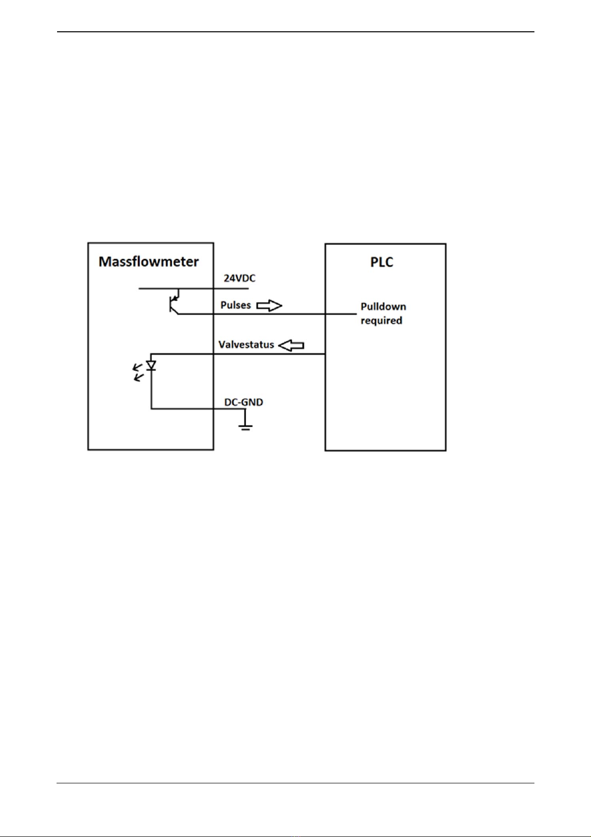
4.3 Status Signal
The dosing flowmeter requires a valve status signal from the control unit.
Pulses are generated only after the status signal is switched on/active. Even after the signal to close
the valve was given, pulses are generated until the flow completely stops. Pulses arriving after the
signal to close the valve are so-called overflow (trailing volume). This depends on the used valve and
can be accounted in the control unit to achieve precisely the required initial set.
5. Output
5.1 Output Signal
A pulse output is available for transmitting of the measured mass flow. The output pulses are active,
i.e., they don’t require an external power supply. Only an external pull-down resistor is necessary,
which, however, is already included in the input circuit of the majority of control units.
The pulse output Idle High.
The pulse-pause ratio is 1:1.
Pulse voltage corresponds to the supply voltage.
The maximum load of the output is 20 mA.
6. Characteristic parameter
6.1 Reference conditions
The dosing flowmeters are calibrated in accordance to the standard method of calibration with the
use of water.
Pressure: 1 bar, Temperature: 20-30 °C

Coriolis Dosing Mass Flow Meter, Series FMD Operating Manual
Bopp & Reuther
Messtechnik GmbH
A
-DE-05809-00 Rev.A
Subject to change. Page 9 of 20
6.2 Measurement error
The measuring accuracy was determined under reference conditions. Measuring times >= 10s.
±0.3% ±(0.01% * Nominal flow rate / instantaneous flow rate)
6.3 Repeatability
Repeatability as a function of dosing time
Dosing time [s] Standard deviation [%]
>5 0,05
>3 0,07
>1,5 0,1
>0,5 0,2
>0,25 0,5
7. Operating Conditions
7.1 Installation conditions
7.1.1 Installation instructions
Warning!
Before mounting and operating the device, carefully read and observe the installation
instructions.
Before mounting or assembling the device,
depressurize
and
cool down the
system
.
Error[%]
ErrorCurve
FlowRange[%]
Coriolis Dosing Mass Flow Meter, Series FMD Operating Manual
Page 10 of 20 Subject to change. A-EN-05809-00 Rev.A Bopp & Reuthe
r
Messtechnik GmbH
7.1.1.1 General information
Only trained personnel who have been authorized by the system operator are allowed to perform
assembly, electrical installations, commissioning, maintenance and operation. You must have
read and understood the instructions and follow their instructions strictly.
The dosing flowmeters manufactured by Bopp & Reuter are precision mass flow meters and
require careful maintenance.
It is necessary to comply with the specified operating parameters, the order confirmation and the
configuration data sheet. If you want to use the device under differing operating conditions,
consult Bopp & Reuther Messtechnik GmbH indicating the factory number.
Installation of the dosing flowmeter must be implemented so that it is completely filled with liquid
even at rest.
To avoid measuring inaccuracies due to gas bubbles or contamination, preventive measures
must be taken.
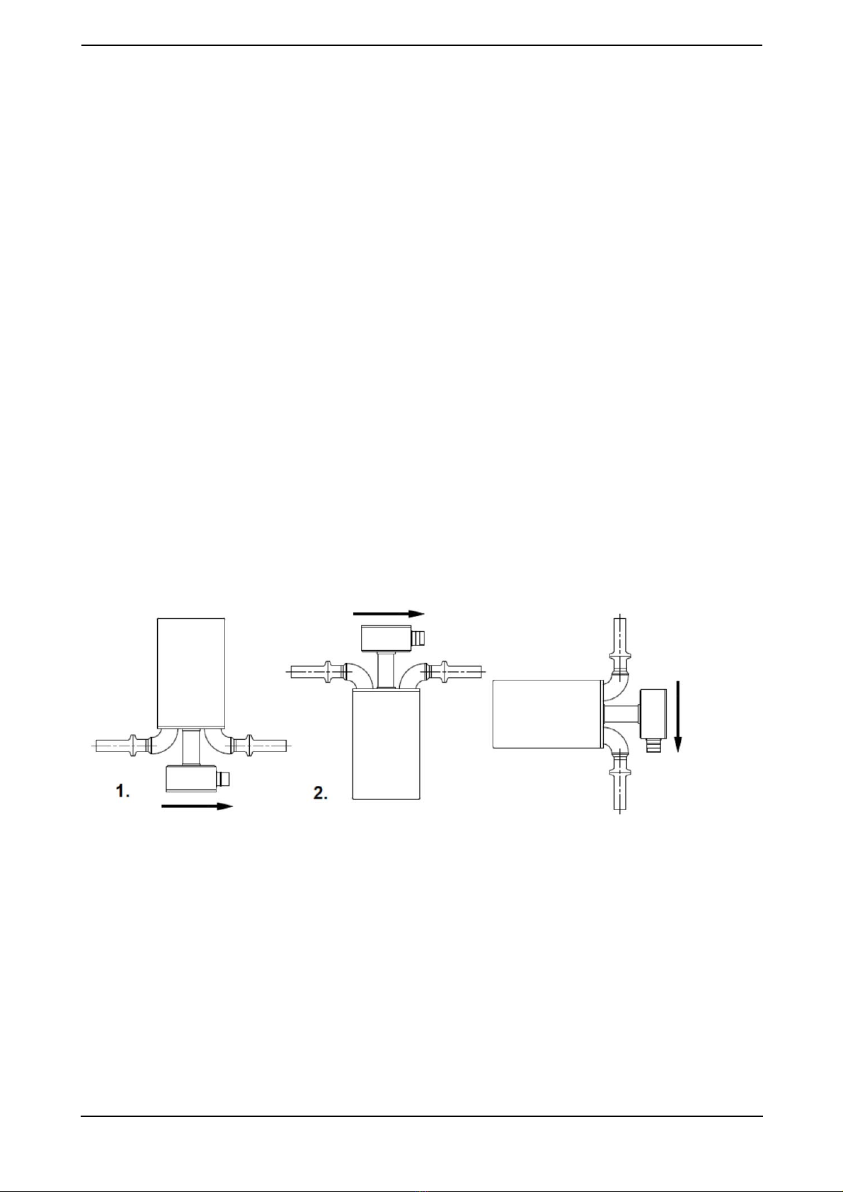
7.1.1.2 Installation
No inlet and outlet piping lines are required. The equipment must be installed in a way to prevent
accumulation of gases and solid particles inside.
1. For the liquids with solids of a greater density than the fluid, in a horizontal line.
2. For the liquids with gases or solids of a lower density than the fluid, in a horizontal line.
3. For all liquids in a vertical line.
The devices can be installed horizontally or vertically (see the drawing). It is necessary to ensure that
the measuring tubes are completely filled during operation. Vertical installation may require a cross-
sectional constriction in order to prevent spontaneous draining of the device during dosing.
7.2 Ambient Conditions
7.2.1. Ambient temperature
0 °C up to +50 °C
3.
Installation type 1 Installation type 2 Installation type 3

Coriolis Dosing Mass Flow Meter, Series FMD Operating Manual
Bopp & Reuther
Messtechnik GmbH
A
-DE-05809-00 Rev.A
Subject to change. Page 11 of 20
7.2.2 Storage temperature
-20 °C up to +70 °C (preferred temperature: 20 °C)
7.2.3 Degree of protection
IP67 IEC 529 / EN 60529
7.3 Process conditions
7.3.1 Media temperature
0 °C up to 90 °C
SIP up to 140 °C
7.3.2 State of aggregation
suitable for liquid media
7.3.3 Media pressure limit
depending on the process connections
7.3.4 Flow rate limit
FMD 06 FMD 08
25 kg / min 45 kg / min

Coriolis Dosing Mass Flow Meter, Series FMD Operating Manual
Page 12 of 20 Subject to change. A-EN-05809-00 Rev.A Bopp & Reuthe
r
Messtechnik GmbH
7.3.5 Pressure Loss
1 bar at nominal water flow 20°C
PressureLoss
PressureLoss[mBar]
FlowRange[l/min]

Coriolis Dosing Mass Flow Meter, Series FMD Operating Manual
Bopp & Reuther
Messtechnik GmbH
A
-DE-05809-00 Rev.A
Subject to change. Page 13 of 20
8. Construction details
8.1 Design / Dimensions
G [mm] H, Height [mm] B, Width [mm] L, Length [mm]
FMD06 275 205 60
*
FMD08 320 240 60
*
*
Depends on the respective technological connection
DIN 32767 Tri-Clamp
L, Length [mm] Weight [kg]
FMD06 190 2
FMD08 220 3
DIN EN 1092 Flange
Length [mm] Weight [kg]
FMD06
FMD08 265 5.5
Coriolis Dosing Mass Flow Meter, Series FMD Operating Manual
Page 14 of 20 Subject to change. A-EN-05809-00 Rev.A Bopp & Reuthe
r
Messtechnik GmbH
8.2 Material
Material / Material No. / ASTM
Sensor case X5CrNi18-10 / 1.4301 / 304
Measuring tube X6CrNiMoTi17-12-2 / 1.4571 / 316Ti
Flow divider X6CrNiMoTi17-12-2 / 1.4571 / 316Ti
Process connection X6CrNiMoTi17-12-2 / 1.4571 / 316Ti
Case of the transducer electronic AlMgSi1 / 3.2315 / -
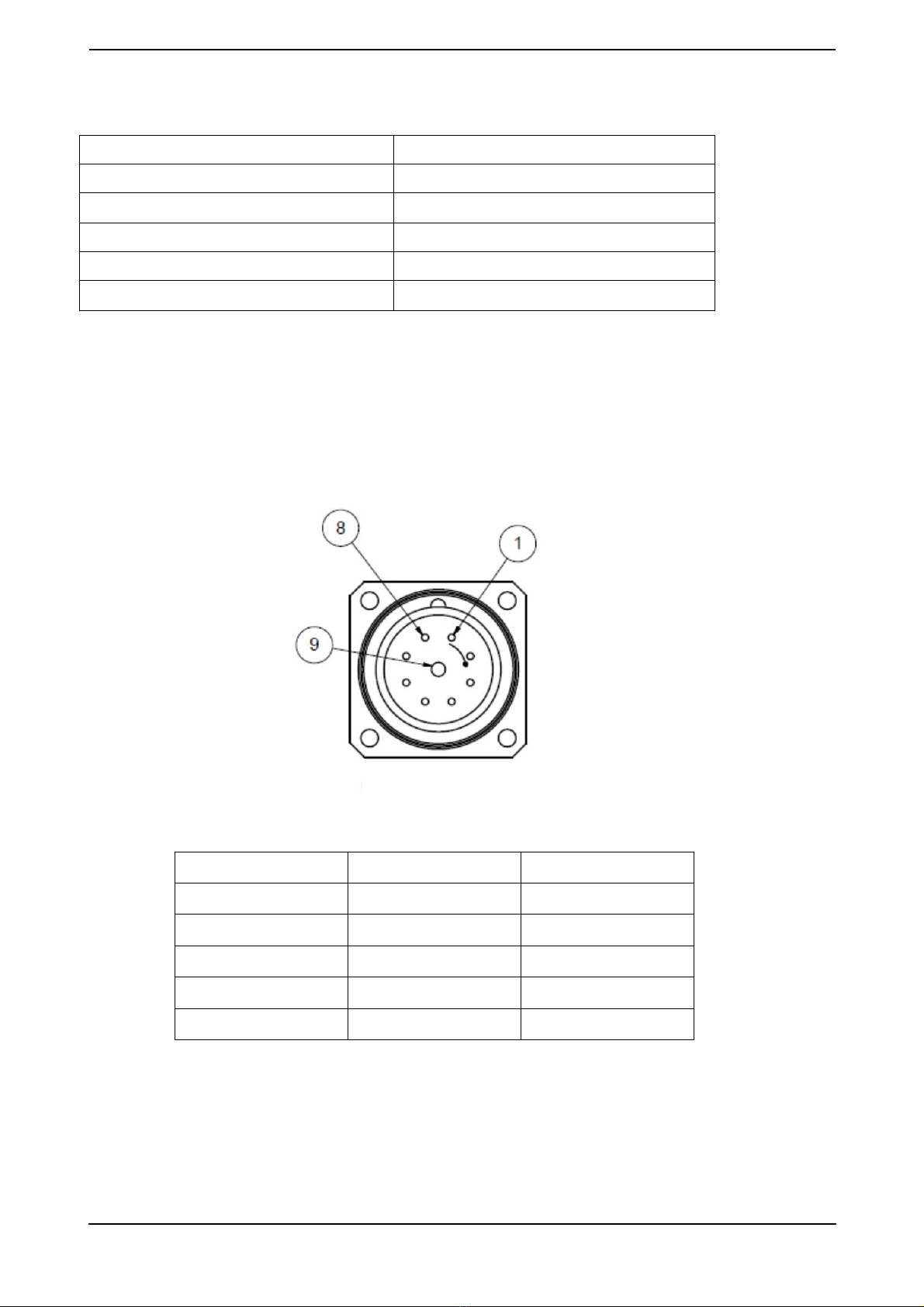
8.3Electrical Connection
The dosing flowmeter is equipped with a plug connector (type: RC-09 Phoenix Contact). The
appropriate interconnect cable is supplied ( 2-81-25826-005).
PIN Function Cable Color
3 Pulse White
5 Valve Status Brown
6 Power + Red
7 Power - Blue
other Do not connect Do not short-circuit
Plug connector
Coriolis Dosing Mass Flow Meter, Series FMD Operating Manual
Bopp & Reuther
Messtechnik GmbH
A
-DE-05809-00 Rev.A
Subject to change. Page 15 of 20
Power Supply Voltage
Rated voltage of 24V DC (12V DC - 36V DC)
Power Consumption
1.5W ~ 60 mA @ 24V DC
Inrush current: 0.5 A (<5 ms)
Pulse
Active pulse output (max. 20 mA; an external pull down resistor is required)
Valve Status
Valve status signal: 24 V DC / 2 mA (12V DC - 36V DC)
9. Calculation pulse frequency
Example for the FM06:
Flow rate: 9 kg/min = 150 g/s
Pulse factor: 63,330 Imp/g
Pulse frequency = flow x pulse factor
Pulse frequency = 150 g/s х 63,660 Imp/g = 9549 Imp/s (Hz)

Coriolis Dosing Mass Flow Meter, Series FMD Operating Manual
Page 16 of 20 Subject to change. A-EN-05809-00 Rev.A Bopp & Reuthe
r
Messtechnik GmbH
10. Certificates and approvals
CE mark:
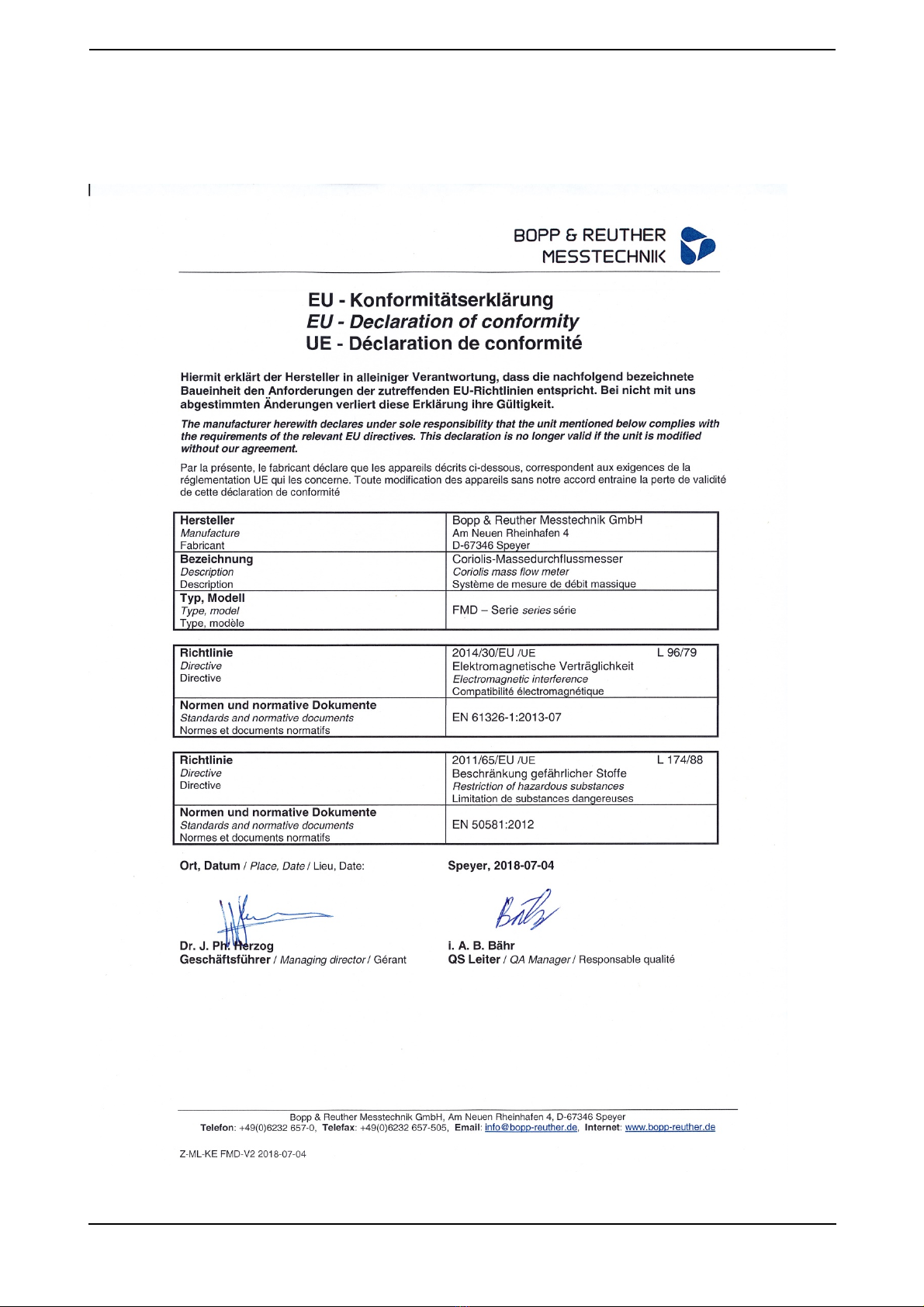
The measuring system fulfills the legal requirements of the EC Directives 2014/30/EU and
2011/65/EU including the amendments and supplements published to date. Bopp & Reuther
Messtechnik GmbH confirms the successful testing of the device by affixing the CE mark.
DIN EN ISO 9001 certified
Directive 2014/30/EU (EMC)
Electromagnetic compatibility according to DIN EN 61000-6-2, DIN EN 61000-6-3
EN 61326-1:2013-07 Electrical equipment for measurement, control, and laboratory use - EMC
requirements - Part 1: General requirements
EN 60529 Degrees of protection provided by enclosures (IP code)
Directive 2011/65/EU Restriction of Hazardous Substances

Coriolis Dosing Mass Flow Meter, Series FMD Operating Manual
Bopp & Reuther
Messtechnik GmbH
A
-DE-05809-00 Rev.A
Subject to change. Page 17 of 20
Apppendix
A. Error diagnostics and fault rectification
The dosing mass flow meter is maintenance-free. If a malfunction should occur or if a wrong
measurement is suspected, please contact Bopp & Reuther Messtechnik GmbH.
Warning!
When working on the electrical connections, the local regulations and all safety
instructions in this operating manual must be observed.
B. Maintenance, Cleaning
Warning!
The operating instructions must be read and observed before installation and
commissioning. The system must be
drained
,
depressurized
and
cooled
down
before mounting or dismounting the device.
Warning!
Make sure that you remove hazardous media from the meter properly!
B.1 Maintenance, Cleaning
Attention!
When cleaning the meter, make sure that the cleaning agent used does not attack the
meter.
The maximum permissible medium temperature for the measuring instrument must be
observed..
If the dosing mass flow meter is to be taken out of operation for a longer period of time, it must be
thoroughly cleaned.
Coriolis Dosing Mass Flow Meter, Series FMD Operating Manual
Page 18 of 20 Subject to change. A-EN-05809-00 Rev.A Bopp & Reuthe
r
Messtechnik GmbH
B.2 Repairs, hazardous materials
The following measures must be taken before you repair the mass flow meter. Bopp & Reuther
einsenden:
In any case, please enclose the Declaration on contamination of products and components
with the description of the fault, the application and the chemical-physical properties of the
measuring medium (see appendix D for form)
Remove all adhering residues of the medium. This is particularly important if the medium is
hazardous to health, e.g. corrosive, toxic, carcinogenic, radioactive, etc.
We must ask you to refrain from returning the goods if it is not possible for you to completely
remove hazardous substances with absolute certainty.
The user will be invoiced for any costs incurred as a result of inadequate cleaning of the device for
possible disposal or personal injury (caustic burns, etc.).
In case of malfunctions of the dosing mass flow meter, please contact our customer service:
Bopp & Reuther
Messtechnik GmbH
Service
Am Neuen Rheinhafen 4
67346 Speyer / Germany
Phone : +49 6232 657-420
Fax: +49 6232 657-561
C. Removal
The device must also be removed properly and disposed of.
Warning!
The operating instructions must be read and observed before installation and
commissioning. The system must be
drained
,
depressurized
and
cooled
down
before mounting or dismounting the device.
Warning!
Make sure that you professionally remove media that are hazardous to health from the
meter and dispose of them properly!
Please note the relevant regulations:
the nationally valid regulations
material separation and recycling of equipment components

Coriolis Dosing Mass Flow Meter, Series FMD Operating Manual
Bopp & Reuther
Messtechnik GmbH
A
-DE-05809-00 Rev.A
Subject to change. Page 19 of 20
D. Forms
D.1 Declaration on contamination of products and components for contractor
You can fill out the form online on our homepage, or copy this page:
Coriolis Dosing Mass Flow Meter, Series FMD Operating Manual
Page 20 of 20 Subject to change. A-EN-05809-00 Rev.A Bopp & Reuthe
r
Messtechnik GmbH
E. Certificates
E.1 EU - Declaration of conformity
This manual suits for next models
2
Table of contents
Other BOPP & REUTHER MESSTECHNIK Measuring Instrument manuals


Popular Measuring Instrument manuals by other brands


Magnetrol
Magnetrol Smart EZ Modulevel Installation and operating manual

SEW
SEW 4338 mO instruction manual

Chauvin Arnoux
Chauvin Arnoux C.A 6528 quick start guide

Agilent Technologies
Agilent Technologies MXA Series Installation note

Signal Hound
Signal Hound USB-SA124B user manual

Novus
Novus N1500G operating manual

Raycus
Raycus RFL-P70QA User instruction

Keithley
Keithley 445 instruction manual

Lufft
Lufft C300 operating instructions

KROHNE
KROHNE SMARTPAT COND 5200 Supplementary instructions

Rohde & Schwarz
Rohde & Schwarz GSM400-MS operating manual

Teledyne
Teledyne TIENet 360 LaserFlow Ex Installation and operation guide