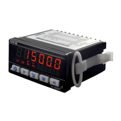
Indicator N1500G
NOVUS AUTOMATION 4/5
Al1t1
Al1t2
Al2t1
Al2t2
Al3t1
Al3t2
Al4t1
Al4t2
Time A arms
The user can set delayed or sequential alar s as
shown in table 3 by defining ti es T1 and T2.
To disable this function just set zero for T1 and T2.
7.3. FUNCTION CYCLES
f.fvnc
F KEY FUNCTION - Options are
oFF - Key no used.
Ho d - Hold PV
AL.oFF - Alar disabled
rESEt - Resets Peak and Valley
PHoLd - Peak Hold
tArE - Tare zeroing
These functions are described in ite 5.2.
Dig.in
Digita Input Function - The sa e function
available for the F key:
oFF - Ho d - AL.oFF - rESEt - PHoLd - tArE
Refer to ite 5.2.
filtr
Input Digita Fi ter - Adjustable fro 0 to 20, this is
used to reduce instability of the easured value.
0 eans the filter is off and 20 eans axi u
filtering. The higher the filter value the lower is the
easured value response.
of et
Disp ay Offset - This a value which is added to the
PV to offset any easure ent deviation or sensor
error. The offset is shown directly in the progra ed
engineering unit.
For °F easure ents the null reference is at 32°F.
bavd
Baud Rate - Serial digital co unication speed in
bps.
Progra able: 1200, 2400, 4800, 9600 and 19200
bps.
Adre
Communication Address - A nu ber which
identifies the instru ent in a ultidrop network.
7.4. CONFIGURATION CYCLE
In.typ
Input Type - Selects the input signal or sensor type
to be connected to the PV ter inals. Refer to table
1.
Changing this para eter will change all other
para eters related to PV and alar s, therefore it
should be the first para eter to be set.
Dp.po
Decima Point Position - Defines the deci al point
position in the displayed value. This applies to linear
input types 0 to 50 V, 4 to 20 A and 0 to 5V as
selected at the “in.tYP” pro pt.
Vnit
Temperature Unit - Selects °C or °F indication. This
pro pt is not shown for input types 0 to 50 V, 4 to
20 A and 0 to 5V as selected at the “in.tYP”
pro pt.
.root
Square Root - This pro pt is only shown for input
types 0 to 50 V, 4 to 20 A and 0 to 5V as selected
at the “in.tYP” pro pt.
Set “YES” and the square root will be applied to the
easured value within the li its progra ed in
“in.LoL” and “in.HiL”.
The display will show the low li it value should the
input signal be below 1% of the range.
In.lol
Input Low Limit - Sets the low li it for input type 0
to 50 V, 4 to 20 A or 0 to 5 V. When the PV
Retransmition is used this li it defines the
corresponding 4 A (or 0 A) in relation to the input
value.
In.kil
Input High Limit - Sets the high li it for input type 0
to 50 V, 4 to 20 A or 0 to 5 V. When the PV
Retransmition is used this li it defines the
corresponding 20 A in relation to the input value.
S(ale
Sca e Factor - Multiplies the displayed value by 10
to increase easured range.
Ovt.ty
Ana og Output Type - Selects the analog output
type to either 0 to 20 A or 4 to 20 A.
8.5 CALIBRATION CYCLE
A input types are factory ca ibrated and fie d ca ibration is
se dom necessary. Shou d it be required the ca ibration shou d
on y be done by experienced personne .
If this cyc e is accidenta y accessed do not touch the or
keys. Just press the index key and go through a cyc es
unti the disp ay shows the main or operation menu.
In.lo(
Input Low Calibration - Sets the Process Variable low
calibration (offset). Several key strokes at or
might be necessary to increment one digit.
In.ki(
Input Hi Calibration - Sets the Process Variable span
calibration (gain). Several key strokes at or
might be necessary to increment one digit.
Ov.lo(
Ana og Output Low Ca ibration - Sets the analog
current output low calibration (offset).
Ov.Ki(
Ana og Output Span Ca ibration - Sets the analog
current output high calibration (span).
(J lo
Co d Junction Ca ibration - Allows the user to
adjust the this calibration directly in degrees for
achieving best results with ther ocouples.
k.type
Hardware Type - These para eters adapts the
software to the hardware available and should not be
changed by the user.
0 - No options
1 - With alar s 3 and 4
2 - With digital input
8. DIGITAL COMMUNICATION
The indicator can be supplied with an asynchronous RS-485 digital
co unication interface for aster-slave connection to a host
co puter ( aster).
The indicator works as a slave only and all co ands are started by
the co puter which sends a request to the slave address. The
addressed unit processes the co and and sends back the answer.
Broadcast co ands (addressed to all indicator units in a ultidrop
network) are accepted but no response is generated.
8.1. CHARACTERISTICS
-RS-485 co patibility with two-wire bus fro the host to up to 31
slaves in a ultidrop network topology.
-Up to 247 units can be addressed by the MODBUS RTU protocol.
-Maxi u network distance: 1200 .
-Ti e of indicator disconnection: Maxi u of 2 s after the
delivery of the last byte.
-Co unication signals electrically isolated fro the rest of the
instru ent.
-Baud rate: 1200, 2400, 4800, 9600, 19200, 38400 or 57600 bps.
-Nu ber of data bits: 8, without parity or even parity
-Nu ber of stop bits: 1
-Ti e to start response trans ission: 100 s axi u delay after
acknowledging the co and.
-Protocol: MODBUS (RTU)
