4
CALIBRATION – LEVEL
CALIBRATION USING PUSHBUTTONS TESTING on BENCH CALIBRATOR
NOTE: Default Error signal setting
from factory = 22 mA.
Direct action 4 to 20 mA at rising level:
1. Calibrate 4 mA/0 % level
Push = start calibration – loop will go to 22 mA.
Push = lock 4 mA value – red ZERO LED must be
ON.
Push = red ZERO LED turns OFF,after ± 5 s LED
flashes 1x to confirm the new 4 mA setting.
Note: DO NOT move level/push any buttons
before the LED has flashed. Restart the
procedure if any of these occurred.
2. Calibrate 20 mA/100 % level:
Establish liquid level at desired 20 mA level
Push = start calibration
Push = lock 20 mA value – red SPAN LED must
beON
Push = red SPAN LED turns OFF,after ± 5 s LED
flashes 1x to confirm the new 20 mA setting.
Note: DO NOT move level/push any buttons
before the LED has flashed. Restart the
procedure if any of these occurred.
3. In case 100 % level cannot be established:
Establish liquid level at highest possible level
Push = start calibration
Push = lock 20 mA value – red SPAN LED will turn
ON
Toggle /=untill loop signal corresponds with %
of actual level. Each two toggles
correspond with 0.1 mA
eg. 80 % level should match:
(20 mA – 4 mA) x 80 %+4mA = 16.8 mA
Push = red SPAN LED turns OFF,after ± 5 s LED
flashes 1x to confirm the new 20 mA setting.
Note: DO NOT move level/push any buttons
before the LED has flashed. Restart the
procedure if any of these occurred.
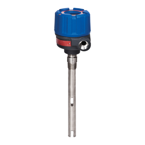
The EZ Modulevel bench calibrator is designed to test the
electronics of the unit. The bench calibrator can also be
used for calibration purpose but the calibration requires fine
tuning versus actual levels in the field.
Slide the electronic head over the open topped enclosing
tube, making sure that the white plastic washer is in
place.
1. Calibrate 4 mA/0 % level:
Slide the adjustment rod completely down into the
enclosing tube
Push = start calibration – loop will go to 22 mA.
Push =lock 4 mA value – red ZERO LED must be
ON
Push =red ZERO LED turns OFF,after ± 5 s LED
flashes 1x to confirm the new 4 mA setting.
Note: DO NOT move the adjustment rod/push
any buttons before the LED has flashed.
Restart the procedure if any of these occurred.
2. Calibrate 20 mA/100 % level:
Align the scale of the adjustment rod with the SG of
your medium
Push = start calibration
Push = lock 20 mA value – red SPAN LED will turn
ON
Push = red SPAN LED turns OFF,after ± 5 s LED
flashes 1x to confirm the new 20 mA setting.
Note: DO NOT move the adjustment rod/push
any buttons before the LED has flashed.
Restart the procedure if any of these occurred.
Ordering code: 031-6107-007
Adjustment rod
Red LED
100 % level,
20 mA output
Zero level, 4 mA output,
bottom of displacer
Desired
level range
(direct acting)
ZERO led
Span led
Error led
Pushbuttons LVDT
White plastic washer
must be installed
For non-Exi units:
Grip ring located
here on
process level
sensors
PC board
"O" rings
Stand
LVDT core
Base & junction
box
BENCH CALIBRATION DOES NOT COMPENSATE FOR ELAVATED TEMPERATURES -
SEE HAND HELD CALIBRATION PROCEDURE
Specific gravity needs to be set in function of selected unit (see partnumber) to establish 100 % level output:
E8x-J/M/A/D/Qxxx-Exx = align adjustment rod with real specific gravity
E8x-K/B/N/E/Rxxx-Exx = align adjustment rod with real specificgravity
multiplied by 2 (density = 0.3 - align with 0.6)
E8x-L/C/P/F/Txxx-Exx = align adjustment rod with real specific gravity
divided by 2 (density = 1.30 - align with 0.65)
IMPORTANT
NOTE: Reverse action: Maintain the same procedure as above described but calibrate 4 mA as 100 % level
(adjustement rod aligned with specific gravity) and 20 mA as 0 % level (adjustement rod entirely in LVDT core)
