SEW 4338 mO User manual
DIGITAL MILLIOHM METER
AND RESISTANCE TESTER
INSTRUCTION MANUAL
4338 mO

INDEX
1. INTRODUCTION.............................
2. SAFETY NOTES.............................
3. FEATURES.....................................
4. SPECIFICATIONS..........................
5. GENERAL.......................................
6. INSTRUMENT LAYOUT..................
7. MEASUREMENT.............................
8. MAINTENANCE..............................
9. FUSE REPLACEMENT...................
PAGE
1
2
3
4
5
6-10
10-12
13
14

-1-
1. INTRODUCTION
NOTE
This meter has been designed and tested According
to CE Safety Requirements for Electronic Measuring
Apparatus, IEC / EN 61010-1 and other safety
standards. Follow all warnings to ensure safe
operation.
WARNING
READ "SAFETY NOTES" (NEXT PAGE) BEFORE
USING THE METER.
CAT IV -Is for measurements performed at the
source of the low voltage installation.
CAT III -Is for measurements performed in the
building installation.
CAT II -Is for measurement performed on circuits
directly connected to the low voltage
installation.
-2-
2. SAFETY NOTES
●Read the following safety information carefully
Before attempting to operate or service the meter.
● Use the meter only as specied in this manual.
Otherwise, the protection provided by the meter
may be impaired.
●Rated environmental conditions :
(1) Indoor Use.
(2) Installation Category IV.
(3) Pollution Degree 2.
(4) Altitude up to 2000 meters.
(5) Relative humidity 80% max.
(6) Ambient temperature 0~40°C.
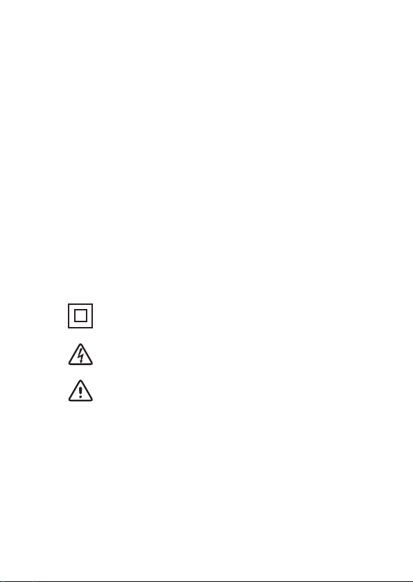
●Observe the International Electrical Symbols listed
below :
Meter is protected throughout by double
insulation or reinforced insulation.
Warning ! Risk of electric shock.
Caution ! Refer to this manual before using
the meter.

-3-
3. FEATURES
●Four terminal measurement for mΩ.
●4-wire method testing(mΩ): 1100.0mΩ / 11000mΩ.
● 2-wire method resistance testing: 110.00Ω /
1.1000kΩ / 11.000kΩ / 110.00kΩ / 1.1000MΩ /
11.000MΩ / 110.0MΩ.(auto ranging)
●Maximum resolution of 0.1mΩ.
●Large LCD (68×34mm).
●Relative mode / Auto-zero mode.
●Data hold function.
●MAX/MIN function.
●Power source: 1.5V "C" battery × 8
●Long battery life and stable power.
●Low battery indication.
●Lightweight, robust & compact.
●"O-Ring" sealed case.
●Safety Standard :
EN 61010-1 CAT IV 20V
EN 61326-1
-4-
4. SPECIFICATIONS
mΩ measurement (4-wire method)
Measuring ranges
(mΩ)
0~1100.0mΩ in steps of 100uΩ
0~11000mΩ in steps of 1mΩ
Accuracy
±0.8% of reading ±4 digits over the
operating temperature range
0°C ~ 40°C,
with the supplied test leads
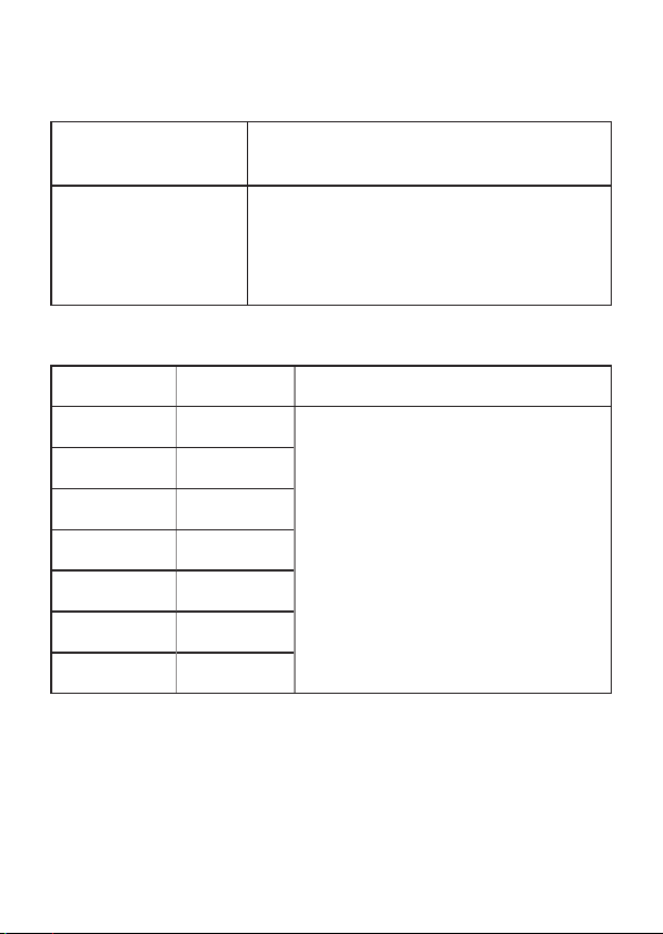
Resistance measurement
Range Resolution Accuracy
110.00Ω 0.01Ω
0~2MΩ: ±(1.2%rdg+3dgt)
2~40MΩ: ±(2.0%rdg+4dgt)
40~110MΩ: ±(8.0%rdg+4dgt)
1.1000kΩ 0.1Ω
11.000kΩ 1Ω
110.00kΩ 10Ω
1.1000MΩ 100Ω
11.000MΩ 1KΩ
110.0MΩ 100KΩ
Auto-ranging
( )
2-wire method

-5-
5. GENERAL
●Protection fuse:
200mA/250V × 1
●Dimensions :
250(L) × 190(W) ×126(D)mm
●Weight :
Approx. 1848g (battey included)
●Power source :
1.5V "C" battery × 8
●Low Battery Indication :
"" sign appears on the display when the battery
voltage drops below accurate operating level.
●Accessories :
Instruction Manual
Test leads
Shoulder belt
Batteries
B

-6-
6. INSTRUMENT LAYOUT
(1) (5)(3)
(7)
(2)
(6)
(8)
(4)
(9)
(10)
(11)
MAX
MIN
HOLD
REL
TEST
TEST
ON
DIGITAL
MILLIOHM
METER
AND
RESISTANCE
TESTER
OFF
1100.0mΩ
11000mΩ
mΩ
(AUTO)
110MΩ
110.00Ω
LOCK
~
● Test Leads
● Special Resistance Test Lead
(Specialized for 2-wire resistance testing)

-7-
(1) C1 Termianl
This is the C1 terminal which is used for mΩ
measurement, for 1100.0mΩ and 11000mΩ
(4-wire testing).
(2) P1 Termianl
This is the P1 terminal which is used for mΩ
measurement, for 1100.0mΩ and 11000mΩ
(4-wire testing).
(3) P2 Termianl
This is the P2 terminal which is used for mΩ
measurement, for 1100.0mΩ and 11000mΩ
(4-wire testing).
This terminal is also the COM terminal for
resistance measurement, for 110.00Ω~110MΩ
(2-wire testing).
(1) C1 Termianl (7) TEST Button
(2) P1 Termianl (8) TEST ON LED
(3) P2 Termianl (9) REL Button
(4) C2 Termianl (10) HOLD Button
(5) Ω Terminal (11) MAX/MIN Button
(6) Function Rotary Switch

-8-
(4) C2 Termianl
This is the P2 terminal which is used for mΩ
measurement, for 1100.0mΩ and 11000mΩ
(4-wire testing).
This terminal is also the COM terminal for
resistance measurement, for 110.00Ω~110MΩ
(2-wire testing).
(5) Ω Terminal
This is the positive input termial for resistance
measurement, for 110.00Ω~110MΩ(2-wire
testing).
(6) Function Rotary Switch
The function rotary switch is for selecting different
functions.
(7) TEST Button
The TEST Button is only available for mΩ
measurement, which includes 1100.0mΩ and
11000mΩ. Press and turn the TEST button for
continuously testing. Remember to release the
TEST Button after the testing.
(8) TEST ON LED
When press the TEST button, the TEST ON LED
glows. When release the TEST button, the TEST
ON LED disappears.

-9-
(9) REL Button
In REL mode, the LCD displays DN+K-DN, where
DN=1,2,3,..., DNis the last value before REL is
pushed, and DN+K is the current value. If REL is
pushed again in REL mode, the meter displays
the reference value. The meter returns to normal
operation if REL is pressed and held for longer
than one second. Pressing HOLD in REL mode
makes the meter stop updating the reading on the
LCD.
(10) HOLD Button
HOLD mode makes the meter stop updating the
reading on the LCD. Enabling HOLD function
in automatic mode makes the meter switch to
manual mode, but the full-scale range remains
the same. HOLD function can be cancelled by
changing the measurement mode, or push HOLD
again.
(11) MAX/MIX Button
The meter displays the maximum or minimum
value of the input in MAX/MIN mode.
When MAX/MIN is pressed for the rst time, the
meter displays the maximum value.
When MAX/MIN is pressed again, the meter
displays the minimum value.
When MAX/MIN is pressed for the third time, the
meter displays current value. The meter returns
-10-
to normal operation if MAX/MIN is pressed
and held for longer than one second. Pressing
HOLD in MAX/MIN mode makes the meter stop
updating the maximum or the minimum value.
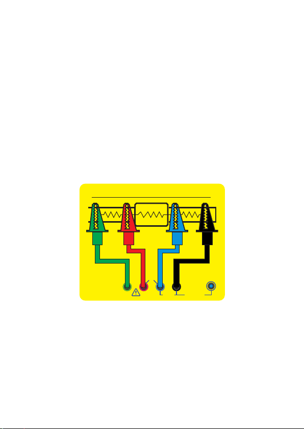
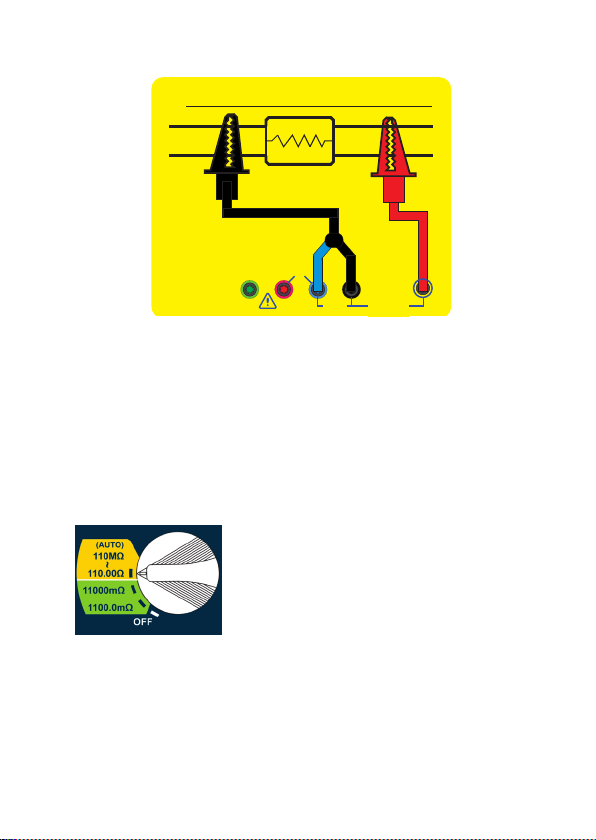
7. MEASUREMENT
mΩ MEASUREMENT(4-wire method).
Use C1, P1, P2, C2 four terminals for 4-wire
mΩ measurement.
Connect green, red, blue, black test leads to C1, P1,
P2, C2 4 terminals.
Connect the test leads to the object or device for
measuring mΩ as Fig 1.
Turn the rotary switch to the position of 1100.0mΩ or
11000mΩ. Press the TEST button to do the
measurement, and get the mΩ reading on the LCD.
DC20V
MAX
RX
RB
RA
Compression
Joint
C1P1C2Ω
P2
0-110MΩ
COM 110MΩ
110.00Ω
~
4-wire method
Fig 1

-11-
When press the TEST button, the TEST ON LED will
glow red.
Please remember to release the TEST button after
mΩ testing, the TEST ON LED will disappear.
It's necessary to release the TEST button after
testing.
RESISTANCE MEASUREMENT(2-wire method).
Use P2, C2, Ω three terminals for 2-wire resistance
measurement.
★ The first step is to connect the special
resistance test lead to P2 and C2 terminals
before turning the rotary switch to the position
of 110.00Ω~110MΩ.
Connect the special resistance test lead to P2 and
C2 terminals as Fig 2, connect the red test lead to Ω
terminal as Fig 2.
TEST
ON
TEST
ON
-12-
Connect the special resistance test lead and the
red test lead to the object or device for measuring
resistance (110.00Ω/1.1000kΩ/11.000kΩ/110.00kΩ/1.
1000MΩ/11.000MΩ/110.0MΩ auto ranging).
Turn the rotary switch to the position of
110.00Ω~110MΩ(yellow area), then get the resistance
reading on the LCD.
It's not allowed to press the TEST button
when the rotary switch is at the position of
110.00Ω~110MΩ(yellow area).
It's not allowed to press the TEST button when do
the 2-wire method resistance measurement.
DC20V
MAX
RX
C1P1C2Ω
P2
0-110MΩ
COM 110MΩ
110.00Ω
~
2-wire method
Fig 2
-13-
8. MAINTENANCE
Battery replacement :
When low battery warning symbol " B"appears,
change new batteries as follows :
(1) Disconnect the test leads from the instrument and
turn off the power.
(2) Unscrew the battery cover and replace with new
batteries(1.5V "C" battery × 8 ).
(3) Re-install the battery cover.
Cleaning and Storage :
WARNING
To avoid electrical shock or damage to the meter,
do not get water inside the case.
Periodically wipe the case with a damp cloth and
detergent. Do not use abrasives or solvents.
If the meter is not used for over 60 days, remove the
batteries for storage.
Batteries
(1.5V "C") × 8
Battery cover
–
+

-14-
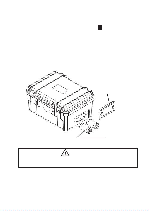
9. FUSE REPLACEMENT
Open the meter case, replace with a new fuse
which has the same specication 200mA/250V,
5×20mm.
Due to our policy of constant improvement and development, we
reserve the right to change specications without notice.
Fuse 200mA / 250V
(5 × 20 mm)
Table of contents
Other SEW Measuring Instrument manuals


