Boqballe L-Trail User manual

Operator's Manual
L-Trail + M -Trail GB


3
M45W, M35W
M45, M35
L20W
L20
=
=
=
=
Table of Contents
Safety ....................................................................................................................................................... 4
Safety and protection ......................................................................................................................................................................4
Legend ............................................................................................................................................................................................5
Liability .................................................................................................................................................... 6
Main settings ........................................................................................................................................... 7
Principle sketch ...................................................................................................................................... 8
L20 / M35-Trail ................................................................................................................................................................................8
M45-Trail .........................................................................................................................................................................................9
Setting and Service .............................................................................................................................. 10
M45-Trail - height adjustable implement carrier ...........................................................................................................................10
M45-Trail - tightening of construction ...........................................................................................................................................10
L20 / M35-Trail and M45-Trail - wheel track adjustment ...............................................................................................................10
L20 / M35-Trail and M45-Trail - wheel hub and wheel bolts .........................................................................................................10
L20 / M35-Trail and M45-Trail - PTO Tractor ................................................................................................................................11
L20 / M35-Trail and M45-Trail - adjustment of wheel hub ............................................................................................................11
Corrosion ............................................................................................................................................... 12
EC-Declaration of conformity .............................................................................................................. 13
Colour codes

4
●Read Operator’s Manual and safety rules before starting.
●Read Operator’s Manual for the PTO shaft.
●Do not leave the tractor cabin without stopping the PTO system of the tractor!
●Turn o tractor engine and all electrical controlling devices during maintenance and other intervention on the
spreader
●Ensure that bystanders maintain a sucient safety distance from the spreader as long as the tractor engine is
on.
●Do not enter the spreader when the tractor engine is on.
●Do not wear loosely tting clothes that could become entangled with moving parts.
●Wear personal protective equipment when necessary or when required by the manufacturer of the fertiliser.
●Stay under the spreader is prohibited.
●Never go between spreader and tractor when engine is started.
●Never enter the spreader using the ladder when the spreader is not mounted to a tractor. The spreader might tilt
over due to unstable weight distribution.
●Safety distance for ying material must be observed.
●Never go behind the spreader with rotating spreading discs.
●Avoid contact with rotating parts.
●Never put hand/object into the hopper with rotating spreading discs.
●Avoid contact as long as parts are moving.
●Never clean the spreader with rotating spreading discs.
●When parking the spreader ensure that the hopper is empty and the ground is solid and horizontal.
Safety and protection
Safety

5
Dieser Dünger-
streuer erfült
die europäische
Umweltnorm
EN 13739-1
This fertiliser spreader
fulfils the European
environmental standard
EN 13739-1
Ce distributeur d'engrais
répond à la norme
environnement
EN 13739-1
Denne gødnings-
spreder opfylder
den europæiske
miljønorm
EN 13739-1
For vort miljø
Für unsere Umwelt
Pour notre environnement
For our environment
xxxx
Legend
Read Operator’s Manual and safety rules before starting.
Never go under a raised spreader.
Never go between spreader and tractor when engine is started.
Never use the ladder when the spreader is not mounted on a tractor.
Safety distance for ying material must be observed.
Never go behind the spreader with rotating spreading discs.
Avoid contact with rotating parts.
Never put hand/object into the hopper with rotating spreading discs.
Avoid contact as long as parts are moving.
Never clean the spreader with rotating spreading discs.
Do not spray water in this area.
Noise level measured inside a closed tractor cabin (level depends on tractor brand and model).
Lashing points for loading and unloading the spreader
Do not step on.
Not designed for boarding purposes.
EN13739-1
Max. loading capacity.
Do not exceed.
Type: Model
No.: Serial number
Year: Manufacturing year
Safety

6
Liability
Liability
You are fully responsible for the setting of the spreader. The spreader must be set according to the fertiliser in use.
Be aware that the fertiliser batch tested in the BOGBALLE A/S test facilities may dier from the fertiliser delivered
to you even if with the same specications.
BOGBALLE A/S cannot be held responsible for any kind of personal injury, crop damage, after eects etc.

7
Main settings
Main settings
If the spreader is mounted on M-Trail or other carriages – the distance from the ground to the spreading discs is
increased from 75 cm, typically up to 100 cm to 140 cm.
Example
Height : 110 cm
Spread width : 24 metres
Spread chart : +4°
Tilt angle M-Trail : (+4° -2°) = +2°
Spread width H: 100 - 140 cm. (see gure 1)
Tilt angle- reduction (according to Spread chart)
12 - 18 metres -4°
20 - 36 metres -2°
40 - 42 metres 0°
H
Top of the crop
Figure 1
8
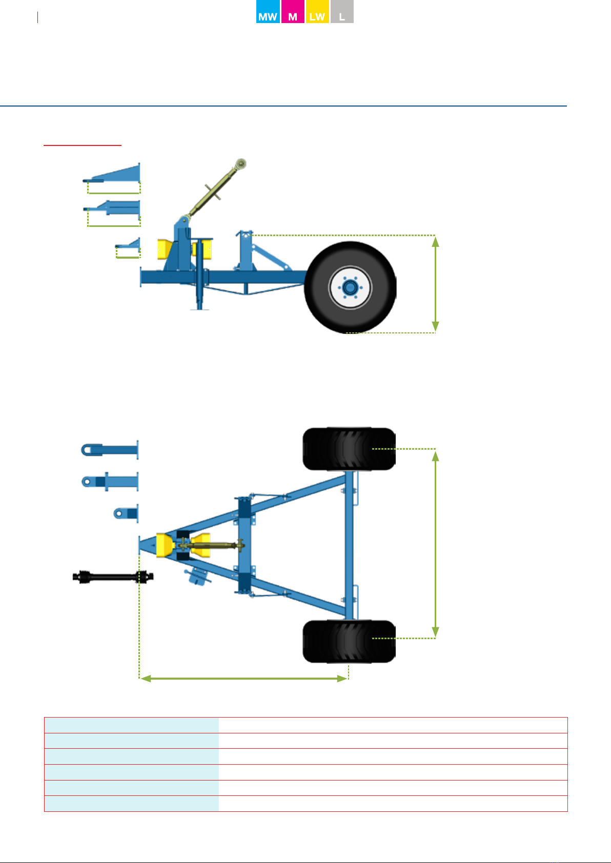
Principle sketch
Net weight 500 kg
Payload max. 4.000 kg
Gross weight max. 4.500 kg
Tyres 400/60-15,5: 4,7 bar
3-point linkage Cat. II / ISO 730/l
Max. driving speed 25 km/h
L20 / M35-Trail
20 cm
20+30 cm
50 cm
95 cm
Min. 170 cm - Max. 200 cm
195 cm
9
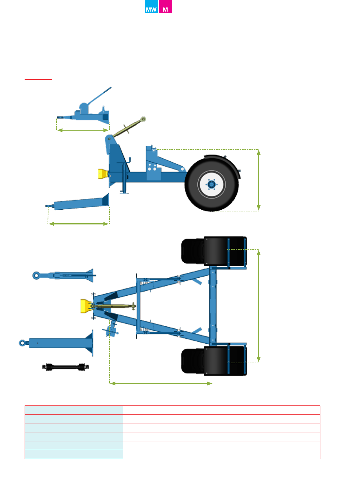
Principle sketch
Net weight 1.000 kg
Payload max. 5.000 kg
Gross weight max. 6.000 kg
Tyres 400/55-22,5: 3,5 bar
3-point linkage Cat. II / ISO 730/l
Max. driving speed 25 km/h
M45-Trail
95 cm
120 cm
Min. 110 cm
Max. 118 cm
Min. 180 cm - Max. 210 cm
200 cm

10
▲
Setting and Service
L20 / M35-Trail and M45-Trail - wheel track adjustment
L20 / M35-Trail and M45-Trail - wheel hub and wheel bolts
M45-Trail - tightening of construction
2 + 2 pcs. M30
Figure 1
M45-Trail - height adjustable implement carrier
The system makes it possible to optimise the spreader height in proportion to the M45-Trail (see gure 1).In cases
where the spreader must be tilted negative (-) the spreading vanes can collide with respectively the guards and
the wheels. If this is the case the lifting system must be raised to a minimum distance of 10 cm between guards /
wheels.
The 2 + 2 pcs. of M30 bolts MUST be tightened at 1200 Nm (see gure 1).
It is recommended to tighten up the construction after 2-3 working hours.
Stepless setting individually on respectively right and left wheel.
●After 2-3 working hours, tighten up the construction at 350 Nm.
After 8-10 working hours:
●Tighten up the 6 wheel bolts on each wheel at 250 Nm.
●Remove the cap from the wheel hub and tighten up the hub at 250 Nm.

11
Figure 1
Setting and Service
L20 / M35-Trail and M45-Trail - adjustment of wheel hub
In case of clearance adjust the lock nut as follows (see gure 1):
●Dismantle the hubcap (1).
●Remove the split pin (2) from the lock nut (3).
●Tighten the lock nut until the clearance is equalised (3).
●Check that the wheel is free running without resistance. A slight clearance is preferred - opposite bearing
resistance.
●Fit a NEW split pin (2) greese and assemble the hub.
The wheel hub must be greased every 50 hours.
Grease nipple (4)
L20 / M35-Trail and M45-Trail - PTO Tractor
●A standard PTO shaft can maximum resist an angle turning of 25º
●A wide angle PTO shaft can maximum resist an angle turning of 80º
If there is a need for turning angles higher than 25º - The carriage must be tted with a wide angle PTO shaft.
Servicing and adjusting the clearance in the taper roller bearings on the wheel hub. It is important to check and
adjust the clearance every 50 hours of use.
After every 50 hours:
●Position the Trailer on a level and stable surface and lift the wheel clear of the ground - free to rotate.
●Place a lever between the tyre and the ground and by lifting and lowering the lever, verifying that that there is no
clearance in the hub.

12
Corrosion caused by insucient cleaning and protection
is not covered by warranty!
Remember always to grease the entire spreader in a corrosion protective
oil. It is not sucient just to wash the spreader, as dried-in fertiliser dust
will absorb water and escalate corrosion.
Mineral fertiliser is extremely corrosive and often with a high content of
nitrogen and sulphur, which combined with water generate sulphuric acid.
Remember to:
• Cover/oil the spreader carefully before using it the rst time.
• Oil seals up joints and connections between components – to pre-
vent fertiliser dust from getting in and building up between the various
spreader parts.
• Wash and grease/oil the spreader after every use.
• Store your spreader indoor
Corrosion

13
Bogballe, 2019-09-01
Manufacturer:
BOGBALLE A/S
Bogballe
DK-7171 Uldum
Phone +45 7589 3266
Fax +45 7589 3766
Declares that machine:
Under carriage for Centrifugal fertiliser spreader:
L20-Trail / M35-Trail / M45-Trail
Is made in conformity with:
Directive of 17th May 2006 conc. mutual approximation of the laws of the member states on machines (2006/42/
EØF), with special reference to the enclosure II, A and enclosure I of the directive, conc. essential safety and health
claims in connection with construction and manufacture of machines.
International/national standards:
DS/EN ISO 12100
DS/EN ISO 13857 1st edition - 2008.03.26
DS/EN 349
ISO 500, 1st edition - 2004.02.01
DS/EN ISO 4254-1 :2015
DS/EN ISO 4254-8 :2018
EC-Declaration of conformity

14
Notes

15
Notes

FIND MORE INFORMATION ON
www.bogballe.com
0431-GB 06-20 V01
This manual suits for next models
1
Table of contents
Other Boqballe Farm Equipment manuals


