JEANTIL MVV 9 User manual
1
INSTRUCTION MANUAL
10/2007
PLEASE READ CAREFULLY AND UNDERSTAND BEFORE USING THE
EQUIPMENT
MIXER WITH VERTICAL BEATERS
540revs/min
MVV 9
MVV 10
MVV 12
MVV 14
MVV 18
MVV 20
MVV 23
MVV 26
ON AXLE OR
TANDEM
ON AXLE
ON TANDEM
N°9
FARMING RANGE –ROBOTISATION –MANURE SPREADERS TRANSPORT RANGE –SLURRY TANKERS
JEANTIL: Head Office JEANTIL : Establishment
6 Rue de la Tertrais- Z.I. de la Hautière- CS 29007 Z.I des Charmilles
35590 L’HERMITAGE 53390 SAINT AIGNAN SUR ROË
: +33(0)2 99 64 04 04 Fax : +33(0)2 99 64 19 56 : +33(0)2 43 06 69 69 Fax : +33(0)2 43 06 69 08
SASU with a capital of 700 000 € - Intercommunity VAT n°: FR76 599200029

2
1.Aim of the Instruction Manual
a) General
The manual concerns all users of the equipment and any person responsible for
assembling, installing, operating, adjusting, servicing, repairing or transporting
the equipment and its accessories.
The manual contains practical information for the correct and safe operation,
handling, adjusting and maintenance of your equipment.
Read carefully and ensure you understand the content before using the
equipment. Comply with the instructions and the safety-related advice.
b) Warning symbols
This warning symbol identifies important advice that must be followed for
your safety. When you see this symbol, be aware that there is a potential risk of injury;
read carefully the advice that follows it and inform other users.
c) Keeping the manual
Always keep this manual within easy reach or at your place of work (or
operating site).
Pass it on to any other user, including if you lend or sell the equipment.
d) Contact details (customer service)
JEANTIL : Head Office
6 rue de la Tertrais
ZI de La Hautière
35590 L’HERMITAGE – France
Phone: +33 (0)2 99 64 04 04
Fax: +33 (0)2 99 64 19 56
Spare parts shop phone: +33 (0)2 99 64 04 02
Spare parts shop fax: +33 (0)2 99 64 09 36

3
e) Statement of compliance with the European ‘Equipment’ directive
(Directive N°98/37/CE)
and to any relevant transposition regulations
The manufacturer: JEANTIL
Rue de la Tertrais
ZI de La Hautière
35590 L’HERMITAGE – France
DECLARES THAT THE EQUIPMENT manufactured by JEANTIL as designated
below:
MVV 9 MVV 10 MVV 12 MVV 14
MVV 18 MVV 20 MVV 23 MVV 26
SERIAL N°: ……………
COMPLIES WITH:
1. Labour regulations
2. The revised European equipment directive N°98/37/EC
3. Revised EMC directive (electromagnetic compatibility) N° 89/336 EC
4. Specific safety standards: NF/EN 703 (mixers, straw blowers, silage feeders)
5. General safety standards: NF/EN/ISO 12100-1
NF/EN/ISO 12100-2
NF/EN 294
NF/EN 349
NF U 02-001-ISO 4254/1
NF EN 1553
NF EN 811
6. Highway Code
SIGNED AT L’HERMITAGE, (DATE)
NAME OF SIGNATORY: JEANTIL Philippe

4
2. Contents
1. Aim of the instruction manual p.2
a. General p.2
b. Warning symbols p.2
c. Keeping the manual p.2
d. Contact details (customer service) p.2
e. Statement of compliance with the European ‘equipment’ directive p.3
2. Contents p.4
3. Equipment identification p.6
4. Standard operating conditions p.7
a. Applications of the equipment p.7
b. Operator qualification p.7
c. Defining the operating stations p.7
d. Environmental conditions p.7
e. Manufacturer’s and user’s responsibilities p.8
5. Technical characteristics p.9
1. Dimensions p.9
2. Stowing and lifting diagram p.11
6. General safety rules p.12
1) General p.12
2) Warning / Pictograms p.13
3) Coupling p.17
4) PTO / Drive shaft p.17
5) Failure (or jamming of the equipment) p.18
6) Maintenance and repair p.18
6. a / General p.18
6. b / Welding operations p.19
6. c / Servicing the tyres p.19
6. d / Electric servicing p.19
6. e / Hydraulic servicing p.19
6. f / Repair p.19
7. Environmental protection p.20
8. Fitting and installation p.20
1- Coupling p.20
2- Drive shaft p.20
3- Hydraulics p.21
4- Electricity p.22

5
9. Adjustments and maintenance p.23
1 - Greasing p.23
2 –Reduction gear p.25
3 - Wheels p.25
4 - Braking p.25
5 - Hydraulic hoses p.26
6 - Hydraulic safety valve p.26
7 - Conveyors p.27
8 –Knives of beater p.27
9 - Stand p.27
10 - Torque limiter with 1 shear bolt WALTERSCHEID p.27
11 - Short period uses p.28
10. Start-up and operation p.28
1 - Important information p.28
2 –Loading p.28
3 - Mixing p.29
4 - Unloading p.29
11. Additional equipment information p.30
Independent hydraulic power unit (Price ref 8210) p.30
12. Cleaning p.31
13. List of technical documents p.32
14. Possible incidents and solutions p.34
6
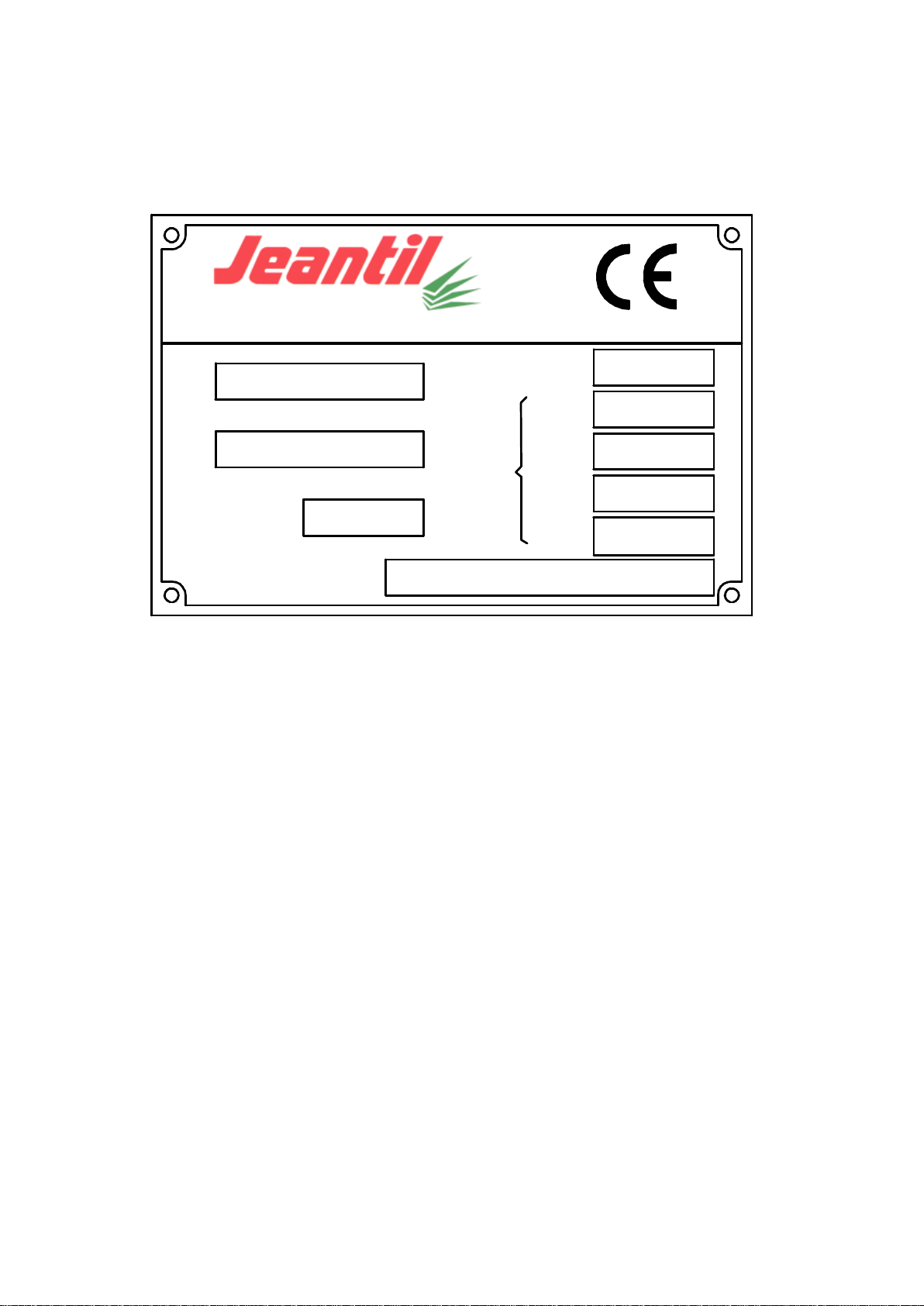
3. Equipment identification
Type
N°de
série
Annéede
construction
P.T.A.C.
Réceptionné
Masses
maximales
admissibles
Anneau
Essieu 1
Essieu 2
kg
kg
kg
kg
20 kgEssieu 3
35590 L'HERMITAGE - FRANCE
Ref: 892 770
Manufacturer’s plate to EC standards.
Never remove the manufacturer’s plate and the EC marking fixed
to the equipment.

7
4. Standard operating conditions
a) Applications of the equipment:
1. This equipment is intended exclusively for general agricultural purposes i.e.: Mixing
and distributing products such as: silage, straw, hay, wrapped bales.
2. Any other use falls outside normal usage and is therefore forbidden.
3. For any other use, please contact the manufacturer.
b) Operator qualification:
1. The equipment must only be used, maintained and repaired by trained operators; see
page 2 “Aim of the Instruction Manual”.
2. Before using your equipment, acquaint yourself with all controls and their correct
operation.
3. All users, prior to using the mixer, must have carefully read this Manual, have
understood it and applied all the safety instructions. Once working, it will be too late to
do this.
c) Defining the operating stations:
1. The only operating station for the equipment is the tractor’s driving station.
2. Never leave the driving station when the engine of the tractor and the equipment are
operating.
3. To access the operating station, use the access devices provided by the manufacturer
(ladder, running board).
d) Environmental conditions:
1. Never approach or remain in the areas that are dangerous when the equipment is in
operation.
2. Adapt your speed and driving style to the lands, roads and tracks. Be cautious and
careful!
3. Do not operate vehicles on slopes (tilting backwards, forwards or on the side) when
there is a risk of tipping or overturning.
4. Do not start or brake abruptly.
5. Operate your equipment with sufficient light to ensure safety; use appropriate artificial
light if necessary (contact your dealer or mechanic).

8
e) Manufacturer’s and user’s responsibilities:
1. Follow all advice contained in this manual regarding levels of knowledge, installation
procedures, operation, adjustment, maintenance and repair.
2. Only use spare parts and accessories that comply with the manufacturer’s
recommendations.
3. Do not carry out any modifications yourself and do not allow others to modify your
equipment and its accessories (mechanical, electrical, hydraulic or pneumatic
characteristics) without requesting prior written approval from the manufacturer.
4. Failure to comply with these requirements may make the machinery dangerous. The
manufacturer disclaims any responsibility if damage or injury arises from such action.

9
5. Technical characteristics
1 Dimensions:
MVV 9 D - 10 D –12D –14D MVV 9 C - 10 C –12 C –14 C
Front or rear direct exit, right or left side Rear, side unloading with conveyor
MVV 9 C - 10 C –12 C –14 C MVV 18D –20D –20TD –23TD –26TD
Front, side unloading with conveyor Front or rear direct exit, right or left side
MVV 18C –20C –20TC –23TC –26TC
Front or rear, side unloading with conveyor
9

10
TYPES
MVV 9
MVV 10
MVV 12
MVV 14
MVV 18
1 axle
MVV 20
1 axle
MVV 20
1 tandem
MVV 23
1 tandem
MVV 26
1 tandem
Capacity
9 m3
10 m3
12 m3
14 m3
18m3
20m3
20m3
23m3
26m3
Unladen weight
3900 kg
4000 kg
4100 kg
4240 kg
6500 kg
6600kg
7050 kg
7250kg
7520kg
Total laden weight
8200 kg
8200 kg
8200 kg
9240 kg
14400kg
13400kg
16210 kg
16210kg
16210kg
Wheel dimensions
30/11.5 x
14.5
400/60 x
15,5
400/60 x
15,5
445/45x19,5
445/45x19,5
445/45x19,5
13,0-65x18
13,0-65x18
13,0-65x18
Inflation pressure
3,5 bar
4,8 bar
4,8 bar
5 bar
5 bar
5 bar
6,6 bar
6,6 bar
6,6 bar
Matériel conforme aux normes de sécurité. Nous nous réservons le droit de modifier nos matériels et leurs caractéristiques à tout moment.
MVV 9 C
front
MVV 10 C
front
MVV 12 C
front
MVV 14 C
front
MVV 9 C
rear
MVV 10 C
rear
MVV 12 C
rear
MVV 14
C rear
MVV 9 D
MVV 10 D
front
MVV 12 D
front
MVV 14 D
front
MVV 9 D
rear
MVV 10 D
rear
MVV 12
D rear
MVV 14
D rear
A
Unloading height
780
830
830
830
780
830
830
830
545
620
620
620
545
620
620
620
B
Overall height
2570
2720
2920
3120
2570
2720
2920
3120
2570
2720
2920
3120
2570
2720
2920
3120
C
Wheel base
3635
3635
3635
3635
3470
3470
3470
3470
3635
3635
3635
3635
3635
3635
3635
3635
D
Overall length
5240
5280
5340
5410
5075
5075
5075
5075
5240
5280
5340
5410
5240
5280
5340
5410
E
Rear overhang
1540
1590
1655
1720
1595
1595
1595
1595
1540
1590
1655
1720
1540
1590
1655
1720
F
Unloading length
2830
2900
2970
3030
320
320
320
320
1720
1750
1820
1890
1130
1140
1210
1280
G
Overall width
2470
2470
2470
2470
2470
2470
2470
2470
2540
2540
2540
2540
2540
2540
2540
2540
H
Width from wheels
2170
2170
2170
2170
2170
2170
2170
2170
2170
2170
2170
2170
2170
2170
2170
2170
I
Height, hopper loading
1380
1420
1420
1420
1380
1420
1420
1420
1380
1420
1420
1420
1380
1420
1420
1420
J
Container height
1700
1800
2000
2200
1700
1800
2000
2200
1700
1800
2000
2200
1700
1800
2000
2200
K
Container length
3580
3670
3800
3930
3580
3670
3800
3930
3580
3670
3800
3930
3580
3670
3800
3930
L
Container overhang
560
600
660
730
560
600
660
730
560
600
660
730
MVV 18
TC fr
MVV 20 TC
fr
MVV 23
TC fr
MVV 26
TC fr
MVV 18
TC rear
MVV 20
TC rear
MVV 23
TC rear
MVV 26
TC rear
MVV 18
TD fr
MVV 20
TD fr
MVV 23
TD fr
MVV 26 TD
fr
MVV 18 TD
rear
MVV 20
TD rear
MVV 23
TD rear
MVV 26
TD rear
A
Unloading height
960
960
960
960
960
960
960
960
850
850
850
850
850
850
850
850
B
Overall height
2760
2860
3060
3260
2760
2860
3060
3260
2760
2860
3060
3260
2760
2860
3060
3260
C
Wheel base
5160
5160
5160
5160
4995
4995
4995
4995
5160
5160
5160
5160
5160
5160
5160
5160
D
Overall length
7640
7670
7735
7800
7475
7475
7475
7475
7640
7670
7735
7800
7640
7670
7735
7800
E
Rear overhang
2480
2510
2575
2640
2680
2680
2680
2680
2480
2510
2575
2640
2480
2510
2575
2640
F
Unloading length
5200
5230
5300
5370
320
320
320
320
4120
4150
4520
4590
1110
1140
1210
1280
G
Overall width
2470
2470
2470
2470
2470
2470
2470
2470
2540
2540
2540
2540
2540
2540
2540
2540
H
Width from wheels
2090
2090
2090
2090
2090
2090
2090
2090
2090
2090
2090
2090
2090
2090
2090
2090
I
Height, hopper loading
1540
1540
1540
1540
1540
1540
1540
1540
1540
1540
1540
1540
1540
1540
1540
1540
J
Container height
1700
1800
2000
2200
1700
1800
2000
2200
1700
1800
2000
2200
1700
1800
2000
2200
K
Container length
5940
6100
6230
6360
5940
6100
6230
6360
5940
6100
6230
6360
5940
6100
6230
6360
L
Container overhang
570
600
660
730
0
20
85
150
570
600
660
730
570
600
660
730
Height for MVV double
beater, single axle:
MVV 18 C
fr
MVV 20 C fr
MVV 18 C
rear
MVV 20 C
rear
MVV 18 D
fr
MVV 20 D
fr
MVV 18 D
rear
MVV 20 D
rear
A
Unloading height
840
840
840
840
630
630
630
630
B
Overall height
2640
2740
2640
2740
2640
2740
2640
2740
I
Height, hopper loading
1430
1430
1430
1430
1430
1430
1430
1430
The equipment complies with safety standards. We reserve the right to change our equipment and their characteristics at any time.
10

11
2 Stowing diagram:

12
6. General safety rules
1) General
1. Never forget that knowledge, awareness and caution are the best way to ensure your
safety.
2. Regulations and rules relating to accident prevention, health and safety at work, and the
operation of vehicles on the public highway must be observed at all times.
3. Chapter 4 (Standard operating conditions) of this Instruction Manual, contains basic
directives that must be followed for the sake of your safety.
4. Make sure that no person, animal or obstruction is located near the equipment before it
is set in motion and throughout its operation or any other manoeuvre.
5. Children must never be allowed near the equipment.
6. Never carry passengers on the equipment.
7. Do not step on the hoods or on any other parts of the equipment, except areas provided
for this purpose (ladder, platform, and means of access to the work station).
8. Before carrying out any work on the equipment, ensure that it cannot be started up
accidentally.
9. All controls (ropes, cables, rods, hoses, etc.) must be positioned in the locations
provided for them so that they cannot accidentally initiate a manoeuvre likely to cause
an accident or damage.
10. Before use and after any adjustment or maintenance, ensure that all protective devices
are in position and in good condition, and that their latches are engaged.
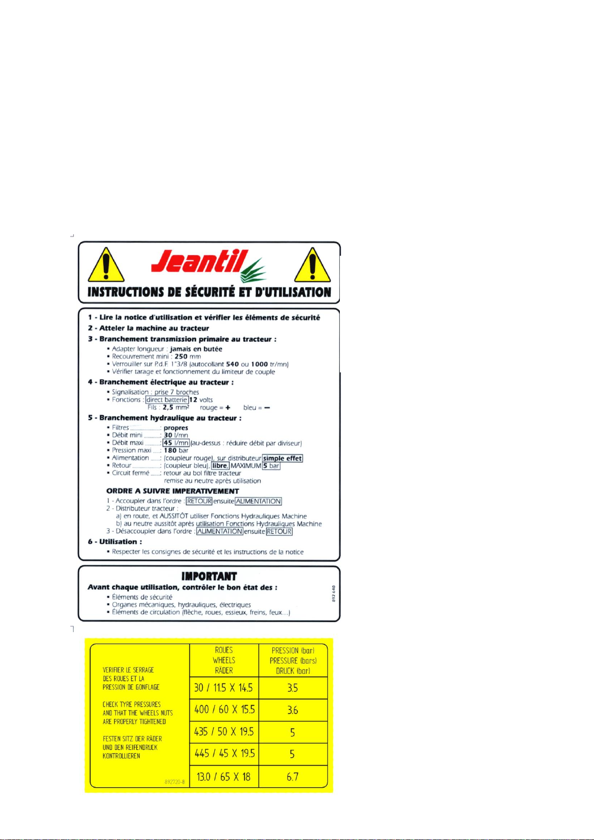
11. Before use, check tightness of screws, nuts, connectors and wheels. Retighten if
required.
12. Do not wear loose clothing, long untidy hair and jewellery that might get caught in the
moving parts of the equipment.
13. Keep your hands, arms and feet well away from any moving parts, even those that are
slow-moving. Keep well away from moving parts.
14. If you detect any unusual noise or vibration, stop the equipment, and identify and
eliminate the cause of the incident before resuming work. Contact your dealer if
required.
13
2) Warning / Pictograms
1. Warnings and pictograms placed on the equipment provide information about safety
measures to be taken, that will contribute to avoid accidents.
2. Make sure that these warnings and pictograms remain clean and legible. If they are
damaged, ask for new stickers from the manufacturer (or agent).
3. If repairs are carried out, check that the replacement parts carry the same stickers as
those that have been removed.
Ref: 892 640
SAFETY AND OPERATING STICKER
CLEARLY placed IN FULL VIEW on the
front of all items of equipment, close to the
components used to connect the unit to the
tractor.
Ref: 892 720
Placed on container, above wheels
Réf : 892 720
Placé sur cuve au dessus des roues
14
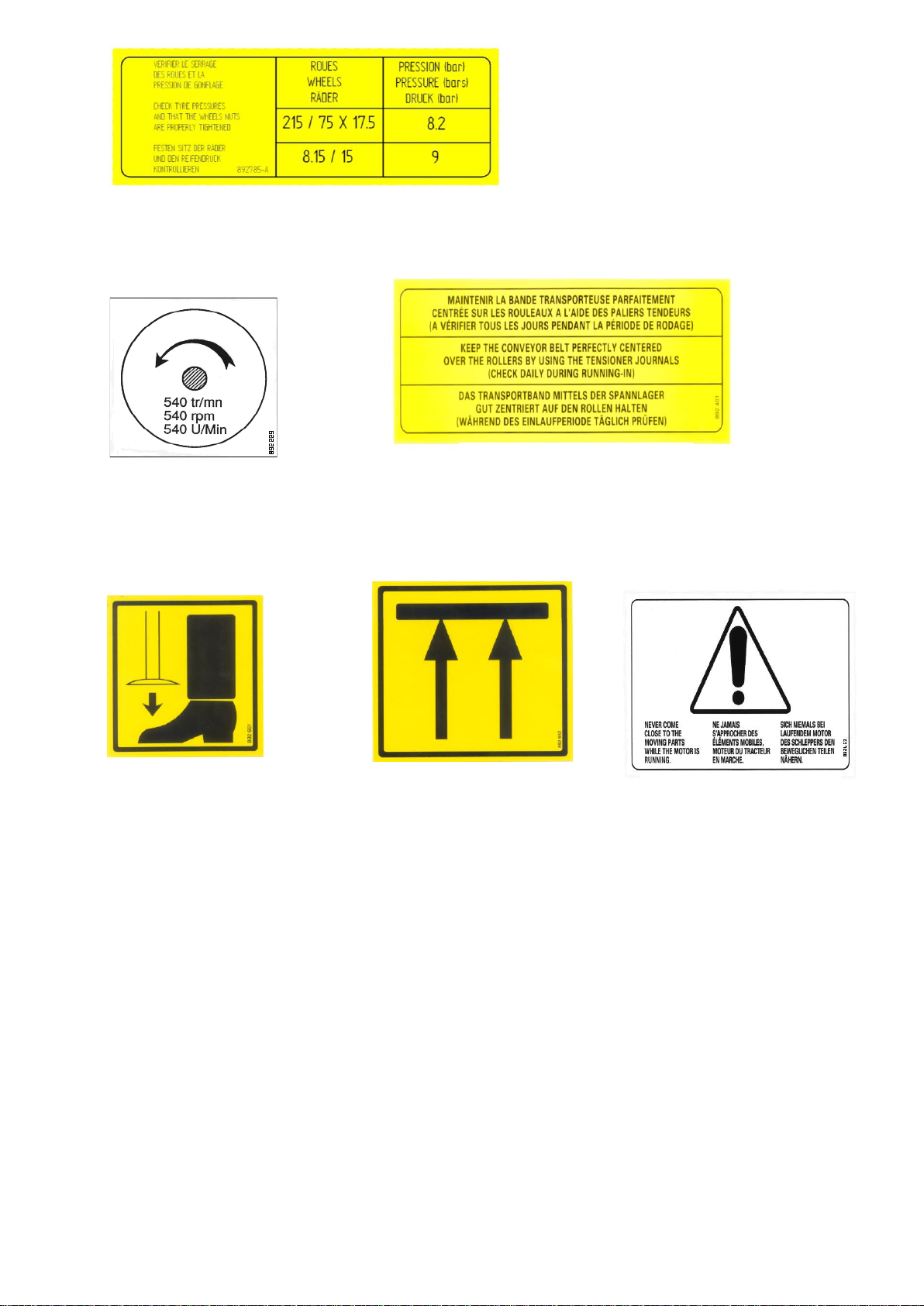
Ref: 892 229
Placed on front casing
Ref: 892 651
Placed on stand
Ref: 892 653
Placed on front
and back part of
chassis
Ref: 892 453
Placed above the
conveyor’s exit sheet-
metal parts
Ref: 892 401
Placed above the 2 front
tensioners of conveyor
Ref: 892 785
Placed on container, above wheels

15
Ref: 892 719
Trapdoor opening indicator sticker
Stuck above the right slideway of
trapdoor
Ref: 892 721
Placed on oil
level reservoir
Ref: 892 652
Placed near the parts
which need greasing
See diagram
Ref: 892 227
Placed on front left side of
container, near ladder
Ref: 892 387
Placed at the back, near the spout

16
Stickers for use of equipment:
892 718 - C : MVV
Débit maxi 45l/min
Max. flow 45/min
Maximaler AusfluB 45 l/Min
Pression maxi 190 bars
Max. pressure 190 bars
Maximaler Druck 190 bars
892717 - B:MVV
1
2
3
4
Réf : 892 718
Placé sur le distributeur commande
manuelle
Ref: 892 717
Placed on electric
unit
Ref: 892 700
Placed at front of machine, on
left side of drawbar on models
MVV 9 to 14
Ref: 892 718
Placed on distributor, manual
control
Ref: 892 701
Placed at front of machine, on
right side of drawbar on models
MVV 18 to 26

17
3) Coupling
1. See chapter 5, Technical characteristics, page 9.
2. Hitching the machine to the tractor must only be carried out using the tractor’s rear
coupling points provided for this purpose.
3. Check the compatibility of the machine with the tractor (minimum engine power, type
of coupling, tractor PTO characteristics, etc.). Keep clear of the area between the tractor
and the machine until you have stopped the tractor’s engine and removed the starter key.
4. Keep clear of the area between the tractor and the machine during any lifting manoeuvre
of the tractor.
5. When manoeuvring, select the lowest possible tractor gear ratio. When coupling, attach
the equipment’s electric control unit in the tractor cab, ensuring that it cannot move
during operations.
6. Once the equipment has been coupled up, the hitch must be locked. Check the coupling
is correctly locked and in good condition before any movement.
7. Check that the equipment’s coupling does not create either an overload or poor weight
distribution on the tractor that might compromise stability:
- Do not exceed the maximum allowed loading for the tractor and equipment
attachment points.
- Where necessary, fit ballast weights to the mounts provided for this purpose in
accordance with the tractor manufacturer’s recommendations.
4) PTO (Power Take-Off) / Drive shaft
1. Read and learn the manufacturer’s instructions for the drive shaft, attached to the
transmission.
2. Check that the PTO guards are in place and in a good condition. Replace them
immediately if damaged.
3. Adjust the length between the tractor and the machine, retaining maximum engagement.
4. The minimum engagement length is 250mm. See white instruction stickers placed on
the front of the machine, n° 892 640 (page 13).
Before each operation, check that the drive shaft is in good condition and that it is fitted
and locked correctly.
5. Only use the drive shaft provided with the equipment or recommended by the
manufacturer.
6. Check before each use that the speed and direction of rotation of the tractor PTO are
compatible with the planned usage of the equipment.

18
5) Failure (or jamming of the equipment)
1. Stop the machine.
2. Disengage the tractor PTO.
3. Wait until all the moving parts are completely at a halt.
4. Stop the tractor engine and remove the starter key or disconnect battery (or electric
connector).
5. Put gear shift into neutral.
6. Engage the parking brake.
6) Maintenance and repair
6. a / General:
1. Maintenance and repair operations must only be carried out by qualified people.
2. Always maintain the equipment and its accessories in perfect working order to ensure
safe and efficient operation.
3. Check the cleanliness of oil.
4. Respect maintenance periods.
Before any servicing or repair:
5. Check the stability of the machine and its components.
6. Lower the equipment to the ground.
7. Fit any provided stability devices (stands, etc.).
8. Check that all moving parts are stopped.
9. Disengage the tractor PTO.
10. Disconnect the hydraulic power hoses between the tractor and the machine.
11. Stop the engine and remove the starter key, disconnect the battery (or the electric
connector).
12. Engage the hand brake.
13. Place the gear shift lever of the equipment into neutral.
14. Allow any component likely to be at a high temperature to cool down.
15. Close the safety valve(s) at the entry of the door cylinder(s) as soon as the door is
open, and before anyone intervenes inside the mixing container (Ex: changing the
knives). Before entering the container, remove the articulated deflector cover of the
trapdoor, for a container with direct exit or of the conveyor, for a container with
conveyor.

19
6. b / Welding operations:
1. When carrying out any welding operation on the equipment, disconnect the electric
connector and the tractor battery.
2. Disconnect and protect any hoses (particularly rubber) and any electric cables to
ensure that they are not damaged by incandescent particles that could cause oil loss or
a short circuit.
6. c / Servicing the tyres:
1. Only carry out work on tyres if you have the necessary specific tools and experience.
2. Incorrect fitting could seriously compromise your safety.
3. If in doubt, call in qualified staff.
4. Do not fit tyres of a different type from those recommended by the manufacturer.
5. Ensure that the tyres are inflated to the pressures recommended by the tyre
manufacturer (see stickers pages 13 and 14).
6. d / Electric servicing:
Before carrying out any work on the electric system, disconnect the electric connector.
6. e / Hydraulic servicing:
1. Place all hydraulic distributors into neutral (rest).
2. Stop the tractor engine and remove the starter key.
3. Before working on the hydraulic system, check that the installation is not under
pressure.
4. Eliminate pressure before disconnecting hydraulic lines.
5. Before restoring pressure in the hydraulic lines, check that all connectors are fully
tightened and that the hydraulic hoses are in good condition and correctly protected.
6. f / Repairs:
1. Any failure that might compromise safety must be eliminated.
2. Carry out immediate repairs on any leak or failure affecting the hydraulic or electrical
systems. These must be done by qualified staff.
3. Do not attempt to find a hydraulic oil leak (under pressure) using fingers.
4. Damaged or defective protective devices or casings must be replaced immediately.
5. Any original protective device fixed to the equipment must not be removed or
modified.
6. Hydraulic hoses that originate from another hydraulic system must not be re-used.

20
7. When a rigid or flexible line is damaged, it must be replaced immediately.
8. Repairs affecting components under pressure or electrically powered require special
tools and procedures. They must only be carried out by qualified staff.
7. Environmental protection
Ground pollution:
1. Make sure that you do not spill or discard in any drainage system used lubricating oil
or other substances such as hydraulic oil…
2. Collect used fluids in sealed, clean containers designed for the purpose. Avoid using
containers used for food or drink bottles.
3. Used tyres. It is against the law to store tyres or to dump them, dispose of them in the
natural environment or burn them in the open air. Take them to a dealer or an
approved collector.
8. Fitting and installation
Hitching to the tractor
1 - COUPLING
1. See page 9 technical characteristics / and page 16 coupling.
2. Read sticker page 13 ref: 892 640.
3. Couple the ring on the drawbar of the mixer to the attachment point or axle hook on
the rear of the tractor.
4. Check the lockings.
2 –DRIVE SHAFT
A/ Primary drive shaft
1. See page 16 PTO / Drive shaft.
2. Read sticker page 13 ref: 892 640.
3. Read the manufacturer’s instructions concerning the drive shaft, attached to the
transmission.
4. Check the safety conditions of the guard. If it shows any sign of damage, it must be
replaced before the equipment is used.
5. The drive shaft is placed between the tractor and the mixer.
This manual suits for next models
7
Table of contents


