Boqballe EX User manual

EX(W)
Trend
3rd edition, GB
0402-24-02-08
EX/EXWTrend
Operator’s Manual

EX(W)
Trend
1
CONTENTS
SUBJECT Page
OVERVIEW ……………………………………..
2
TECHNICAL SPECIFICATIONS …………………………………….. 3
STANDARD EQUIPMENT …………………………………….. 4
OPTIONAL EQUIPMENT …………………………………….. 4
MAINTENANCE AND CARE
Normal maintenance………………….. 5
Special maintenance……………………. 6
Lubrication………………………………. 7
Generally…………………………………. 7
Spreading vanes…………………………. 7
…………………………………….. 5
GUARANTEE / RESPONSIBILITY …………………………………….. 8
GENERALLY ……………………………………..
8
SAFETY and PROTECTION AGAINST ACCIDENT …………………………………….. 8
SPREADING SYSTEM …………………………………….. 9
SETTING SYSTEM …………………………………….. 10
FUNCTION – How to do …………………………………….. 11
MACHINE SETTINGS / Normal and late application
PTO- speed…………………………… 13
TILT ANGLE…………………………….. 14
HEIGHT,
incl. late application….... 14
SETTING OF QUANTITY……………….. 16
VANE / SPREAD WIDHT…………….. 17
FUNCTION SPREADING VANE…….. 18
Trend SYSTEM……………………………. 19
…………………………………….. 13
NORMAL spreading
Practical test……………………………….. 21
Test with test trays……………………… 22
Examples of NORMAL spread patterns...24
…………………………………..… 21
HEADLAND spreading TO BORDER
Practical test………………………………. 28
Test with test trays……………………… 28
Ex. of HEADLAND spread patterns….. 29
…………………………………….. 26
HEADLAND spreading FROM BORDER
Ex. of HEADLAND spread patterns.. 31
…………………………………….. 30
REDUCED SPREAD WIDTH …………………………………..… 32
TURNING AT THE HEADLANDS …………………………………..… 33
SPREADING ON NON-RECTANGULAR FIELDS …………………………………….. 34
CHECK THE TRACTOR – before use …………………………………….. 35
CHECK THE SPREADER – before use …………………………………….. 35
PRACTICAL HINTS …………………………………….. 36
EXW Trend – special …………………………………….. 37
USE OF CALIBRATION RATE CHECK KIT
REST EMPTYING……………………….. 38
…………………………………….. 38
NB ! Fitting instruction for different options – are supplied with the options.

EX(W)
Trend
2
OVERVIEW
F) Setting handle
Degree meter
ICS-deflector
Inte
g
rated Center S
y
stem
Hopper
To
p
link fixture
J) Link pins
Transmission
I) Angle- transmission
G) Connection rod
for shutter
D
)
Shutte
r
A)
Cardan joint
B) Telescope
Serial No. plate
E) Setting axle
I) Angle transmission
H)
Friction clutch
C
)
A
g
itato
r
EX(W)
Trend
3
TECHNICAL SPECIFICATIONS, general
•Hopper volume : EX/EXW 1.000 – 2.500 Litres
•Hopper capacity : EX Max. 3.000 Kg.
•Hopper capacity : EXW Max. 2.500 Kg.
•Spread width : EX/EXW 12 – 36 Metres
•Spreading capacity : EX/EXW Ca. 0,35 – 400 Kg/min.
•3-point linkage : EX/EXW Cat. II / ISO 730/I
TECHNICAL SPECIFICATIONS, specific
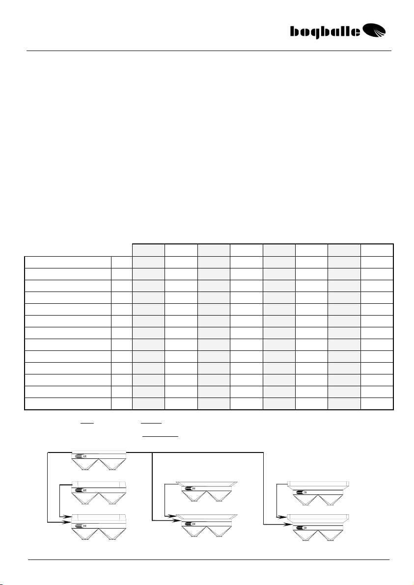
The EX / EXW machine has as standard a hopper volume of 1.000 litres.
•The volume can be increased in steps of 300 litres by mounting extensions.
•The extensions can be supplied as Small (S) or as Large (L) extensions.
SPECIFICATION 1.000 1.300 S 1.600 S 1.600 L 1.900 S 1.900 L 2.200 L 2.500 L
Load height cm. 98 110 c98/122 c98/118 c110/134 c110/130 c118/135 c130/147
Hopper volume Liter 1.000 1.300 1.600 1.600 1.900 1.900 2.200 2.500
Hopper capacity Kg. 1.100 1.450 1.750 1.750 2.100 2.100 2.400 e2.750
Hopper width cm. 220 220 220 270 220 270 270 270
Hopper depth cm. 120 120 120 130 120 130 130 130
Hopper opening cm. 214x111 214x111 207x104 264x121 207x104 264x121 264x121 264x121
Fill opening, Gate cm. 170 d200/250 170 d200/250 250 250
Outside EX – L x W cm. 154x220 154x220 154x220 159x270 154x220 159x270 159x270 159x270
Outside EXW – L x W cm. 167x220 167x220 154x220 172x270 154x220 172x270 172x270 172x270
Net weight, EX Kg. 350 370 385 390 405 410 430 450
Net weight, EXW Kg. 430 450 465 470 485 490 510 530
Total weight, EX Kg. 1.450 1.795 2.135 2.140 2.480 2.485 2.830 3.200
Total weight, EXW Kg. 1.530 1.875 2.215 2.220 2.560 2.565 2.910 3.030
cWithout back gate dWidth across in opening eEXW max. 2.500 Kg
The EX machine can be extended to 2.800 litres in case ”lightweight fertilisers” < 1,0 Kg/litre are used.
1300 S
+ 1600S + 1600 L + 2200 L
1900 S 1900 L 2500 L

EX(W)
Trend
4
STANDARD EQUIPMENT
The EX / EXW machine is from factory supplied with all necessary standard equipment.
•PTO shaft
•Headland spreading TO BORDER, Trend with manual reversible transmission.
•Mud guards
•Agitators, Excentric free- and slow rotating.
•Screens to open, 2 units with cones.
•Closing of only one outlet, choose right or left.
•Reduction outlet for micro granules, reduction of outlet, without use of tools.
•System for late application, link pins can be mounted in 2 heights.
•Degree meter, for setting the angle of the machine.
•Transmission, with reversible gear and friction clutch / overload coupling.
OPTIONAL EQUIPMENT
The following options can be supplied for the machine:
PART DESCRIPTION DIM.
REF. NR.
Extension EX/EXW 300 / 1300 S 220 x 120 cm 4950-01
do. EX/EXW 600 / 1600 S / Gate 220 x 120 cm 4950-21
do. EX/EXW 600 / 1600 L / Gate 270 x 130 cm 4950-10
do. EX/EXW 1200 / 2200 L / Gate 270 x 130 cm 4950-41
Hydraulic control Incl. tube w/valve 4581-01
Cable control Only between 0 and 250 Kg/min. 4580-01
Calibrator 2003 Electric setting and operating system 4585-01
Headland manual, TO BORDER Mounting parts, TO BORDER 4690-01
Headland manual, FROM BORDER Mounting parts, FROM BORDER 4790-10
Cable system Remote control from tractor seat 280 cm 4690-28
Cable system Remote control from tractor seat 380 cm 4690-38
Cable system Remote control from tractor seat 480 cm 4690-48
Calibration rate check kit Rate check kit / Rest emptying 4953-30
Hydraulic motor Incl. of tubes and valves 4955-20
A-frame Triangle for 3-point linkage 9988-93
Hopper cover Hopper system 1000 / 1300 220 x 120 cm 4955-50
do. Hopper system 1600 S 220 x 120 cm 4955-70
do. Hopper system 1600 L / 2200 L 270 x 130 cm 4955-90
Transport wheels 4 units Ø 110 mm plastic wheels 4951-60
Light kit 2 units lamps / reflectors/wire w/plug 4951-50
Link pins cat. III 2 units / Ø 36,6 4223-30
Row equipment 2- row equipment 4952-03
do. 4- row equipment 4952-01
do. Supplement kit from 4 to 6 rows 4952-02
Draw bar For 4-wheeled trailer 4910-10
Connection system For 36 metres (250 – 400 Kg/min.) 4952-80
Chassis kit Tubes: LP 400 x 15,5 1800-53
Trend vanes, cpl. System E1-T (L/R) 12 – 18 metres 4650-12
do. System E2-T (L/R) 20 – 24 metres 4650-20
do. System E6-T (L/R) 28 – 36 metres 4650-28
All BOGBALLE products are subject to a continuous development.
EX(W)
Trend
5
MAINTENANCE AND CARE
NORMAL MAINTENANCE
The BOGBALLE machine is manufactured in such a way that it requires a minimum of
maintenance.
In the construction it is considered that cleaning and lubrication can be completed quickly
and thoroughly – without taking apart the machine.
The surface treatment consists of a robust powder paint – in addition all essential wear parts
and bolt assemblings are made of stainless steel.
Many of the components of the machine are greased once and need no extra maintenance,
for instance the central and angle gears of the transmission.
The maintenance mentioned below is absolutely necessary!
”If the machine is maintained – it will still be new - in 5 years ! ”
”If the machine is not maintained – it will be old – next year ! ”
&The machine must always be thoroughly cleaned after use. The cleaning
should be done with water perhaps with soap in it. When using a high-
pressure cleaner only use low pressure and do not clean direct on the axle
seals of the transmission.
Do not use grease-removing cleaning liquid – without giving the machine –
just after drying – an application of anti corrosion oil.
)Remember always to grease all of the machine in a corrosion protecting
liquid (for instance oil). It is not sufficient just to wash the machine.
*•Without protection, rust might arise within a few hours in areas,
where the paint has been damaged – because fertiliser salts hold
acid and is therefore most corrosive.
Any paint damage should be cleaned and painted. A possibility could also be to treat the
damage by Tectyl or a similar product.
*Please consider that cleaning products and corrosion protecting liquids
might include dissolvents that might dissolve the glue fixing the transfers.

EX(W)
Trend
6
SPECIAL MAINTENANCE, Friction clutch
&
)
The transmission of the machine is equipped with friction/overload clutch.
The friction clutch is a most important component protecting against
overload – and a damaged transmission / PTO- shaft.
The friction clutch protects especially the reversible gear system of the
Trend transmission. The Trend-system is based on an inpact clutch.
*The friction clutch must be maintained, and it must be checked, that it
is not corroded.
The friction clutch must ”slip” at START of the tractor PTO.
If the clutch does not slip – the transmission will be damaged.
&The friction clutch ”slips” approx. 1-2 turns at START of the tractor PTO. This reduces the
load on the components of the transmission to approx. 1/10 of the load to which the
transmission is exposed, if the coupling is not able to ”slip”.
*As principal rule the coupling must be separated and cleaned if the
machine has not been used for more than 6 months. Alternatively
minimum once a year.
)It is always necessary to START the tractor PTO ”slowly /
smoothly” !
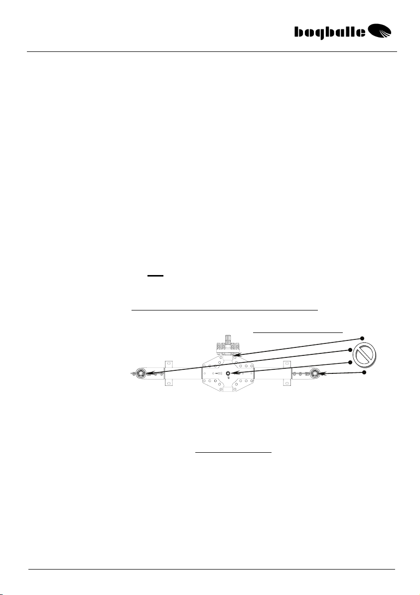
GUIDANCE HOW TO CLEAN AND ADJUST THE FRICTION CLUTCH.
&Demount the 6 adjustment bolts of the clutch – and the clutch
is separated.
*Clean all the ”slip surfaces”
for rust (perhaps with a wire
brush) – and the adjustment
bolts w/springs are
reassembled.
The clutch surfaces should not be
greased with oil/grease !
)The friction clutch is adjusted by a torque wrench, so that the
splined axle slips at:
If a torque wrench is not available – you can in an emergency
– adjust the bolts so that the length of the spring corresponds to
30 mm. The procedure is not recommended.
15 – 18 Kg/m
145 – 175 N/m
ADJSUTMENT BOLTS
w/ SPRINGS
Splined axle
2 coupling plates

EX(W)
Trend
7
LUBRICATION
*The components below must be greased according to below instruction.
See the explaining sketch in the paragraph ”OVERVIEW”.
LUBRICATION ONCE A DAY:
POS. COMPONENT INSTRUCTION
A
B
C
D
E
F
G
Cardan joint and lock of the PTO
Telescope axles of the PTO
Agitator R and L (Under cone)
Setting and closing shutter (Bottom of hopper)
Adjustment axle (Cross axle w/ 4 bearings)
Setting handle (Axle w/ 2 bearings)
Connection rods (Rods between axle and shutters)
Use grease
Use grease
Use grease
Use oil
Use oil
Use oil
Use oil
*
Note
C)
If the agitators are overgreased, a high pressure might restrict the rotation of the
agitator bearing. If this is the case the lubricator nipple must be demounted, which will
release the pressure. Grease sparingly – e.g. one pump/season.
PARTS GREASED ONCE:
&The central and angle gears are filled with special grease and needs no
lubrication.
GENERAL
)A new machine will always ”move” a little bit in all nuts +bolts.
Therefore all nuts and bolts of the machine must be retightened - first
time it is put into operation - after 5 to 8 hours’ operation.
Exception is the bolts in the central and angle gears – these are locked
with lock-tite.
*Be aware that stainless nuts + bolts might ”weld together” When mounting
such bolts – the thread must be greased with cutting lubricant or copper
grease !
SPREADING VANES
*The spreading vanes are manufactured of high quality manganese steel,
NM12.(MN 12 has a hardness corresponding to 3 times the hardness of stainless steel).
But still the vanes will be worn due to modern and abrasive fertilisers.
Therefore the vanes are to be considered a wearing part – that must be
exchanged dependent on the quantity and type of fertiliser.
Always clean the contact surfaces of the vanes and the spreading disc
for dust etc – before mounting and tightening the vane !
IF HOLES ARE WORN IN THE VANES THEY MUST BE
EXCHANGED AT ONCE!

EX(W)
Trend
8
GUARANTEE / RESPONSIBILITY
•Claim conditions are according to Danish legislation. Service and repair are made free
of cost within 12 months from date of purchase on the following conditions:
•That the failure is due to construction or material faults
(Normal wear, missing maintenance and misuse not included).
•That the failure is not due to not original components / equipments.
•That persons with no technical knowledge to the machine have not tried to repair.
•Compensation for person or crop injury do not fall on the supplier.
GENERALLY
This machine is intended for spreading all common types of fertiliser.
Spreading of other flowing materials might also be possible. If so we draw the attention to
data list of the material concerned in order to determine possible safety or health measures
to be taken.
If the machine is used for spreading material which is not defined in the spread charts for
the spreader, the manufacturer of the machine can never be held responsible.
SAFETY and PROTECTION
The transmission system of the machine:
PTO shaft, friction clutch and spreading discs w/vanes – must be considered”as
dangerous”, and absolute care must be taken with these machine parts, especially in
connection with rotation of the tractor PTO system.
DO NOT LEAVE THE TRACTOR CABIN – WITHOUT STOPPING THE PTO
SYSTEM OF THE TRACTOR!
Except when you have to calibrate the machine.
•Never go behind the machine – with rotating spreading discs.
•Never go under the machine – with rotating spreading discs.
•Never clean the machine - with rotating spreading discs.
•Never put hand/object into the hopper – with rotating spreading discs.
•Always check that the spreading vanes are correctly fixed.
•Check that the protection tubes of the PTO are intact.
•Check that the security chain of the PTO is fixed.
•Check that top link and top link pins are intact and secured by lynch pin.
•Check that lift arms and link pins are secured by lynch pin.
EX(W)
Trend
9
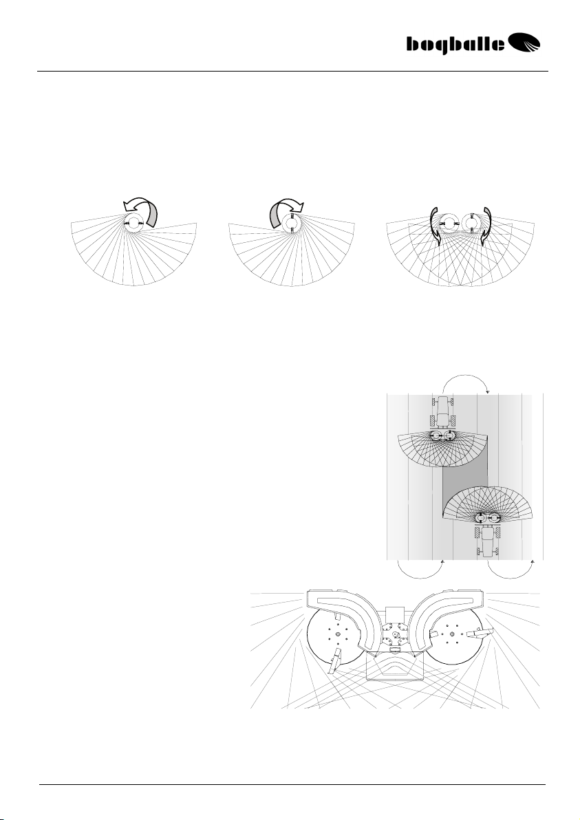
SPREADING SYSTEM
The BOGBALLE spreading system is base on an Integrated Center System – ICS, where
the spreading discs of the machine during NORMAL spreading – rotate against each other
– and spread in a radius of 180°, with a 100 % overlap.
This means in practice that right and left spreading disc form two opposite spread patterns –
overlapping each other.
Each spreading disc spreads the full spreading width. That means that the fertiliser from the
two spreading discs A and B – overlap each other. The spread width is for almost all types
of fertiliser twice as wide as the distance between the tramlines.
This way you achieve a 4-double overlap – which ensures a most even distribution of the
fertiliser.
As shown in the diagram the spreading is made from the
present tramline – to the middle of the next two tramlines.
The spreading system is developed in such a way that you
are able to spread the fertiliser with a minimum of
machine setting.
This means in practice that you get a uniform distribution – no matter
which type of fertiliser and without special settings.
The BOGBALLE machine is therefore only equipped with one setting
handle – for setting the quantity.
The spreader’s ICS system
includes the special X-deflector.
This deflector will help ensuring
an optimum distribution and
overlap at large spread widths.
The passage of the fertiliser
through the X-deflector will
result in a small amount of dust building – dependant on the quality of the fertiliser –
because the X-deflector functions as a wind tunnel.
This will not influence the eveness of the distribution.
+ =

EX(W)
Trend
10
SETTING SYSTEM
The setting system consists of a setting handle, different connection rods and outlet
shutters.
SETTING HANDLE , Hydraulic/CALIBRATOR
The connection rod of the setting handle must be
mounted in such a way that the shutters of the spreader
are closed – when the setting handle is placed on the
scale ciffer ”0”.
The adjustment is made on the connection rod.
As standard the connection rod is mounted in Pos. 1
(Ø8 mm.)
In case very large quantities being used on 28 – 36
metres’ spread width, a Pos. 2 connection rod (Ø10 mm.)
can be used as option.
ADJUSTMENT SHUTTERS
The shutters in the adjustment system are factory set so
that the machine distributes the fertiliser symmetrically.
That means that the fertiliser is shared in equal quantities
to each side of the machine.
The adjustment shutters must be adjusted so that the
shutters close exactly in the middle of the V-mark of
the bottom plate.
Normally you should not adjust the 4 connection rods
connecting the adjustment axle of the machine and the
shutters of the machine. These connection rods should
only be adjusted in case the system has been dismantled
and therefore misadjusted.
The setting is of great importance for the symmetry of the spread pattern.
Be aware that the adjustment shutters do not open equally in comparison to the V-mark.
This assymmetric function ensures automatic adjustment of the feed point for precise
spreading.
Connection rod
Pos. 1
Pos. 2
V-mar
k

EX(W)
Trend
11
OUTLET SHUTTERS
The machine’s hopper bottom is equipped with a turnable outlet shutter for right and left
side respectively.
The outlet shutter can be locked in three different positions.
0 Closed outlet (Calibration / rest emptying)
1 Normal outlet (For fertiliser)
2 Reduced outlet (For micro granules)
”2” .is only used if stated in the contents page of the spread chart.
The outlet shutters are set by pressing the handle
(A) against the hopper – and at the same time turn
the outlet shutter to the required position. The
handle locks the shutter in the U- cut.
FUNCTION
•The Trend sytem gives distribution of fertiliser a totally new dimension, where
PRECISION, USER FRIENDLINESS and RELIABILITY, are the three main areas
in which BOGBALLE
EX(W)
Trend
– differs most essentially from the other products
in the market.
•The Trend system is the only transmission in the market with reversible rotation
direction.
The reversible rotation direction gives the optimum result for use of the rotation
direction, … towards the centre is most suitable for spreading on the main area on
the field, NORMAL spreading – and the reverse rotation direction is most suitable
for HEADLAND spreading at field borders.
…..high PRECISION is achieved, no matter which type of spreading !
•The Trend system ensures an optimum result, with a minimum of setting.
2
0
1
A
U- cu
t

EX(W)
Trend
12
•The transmission of the machine with reversible rotation direction together
with the double function of the spreading vane ensure that the spreader can be
transformed from NORMAL spreading to HEADLAND speading – by
making only one change – which can even be set with cable connection from
the driver’s seat.
•The full 180°overlap is the key reason for achieving an optimum NORMAL
spread pattern – without other setting of the machine. Therefore neither the
length or the angle of the vane must be adjusted. Also no side adjustmnet is
necessary.
•The feed point of the machine is automatically shifted in comparison to the
quantity of fertiliser spread. This means that the feed point need not be set.
…..high USER FRIENDLINESS is achieved, no matter which spreading!
•The design of the machine ensures maximum flexibility – without making
compromises.
•The slow rotating agitators of the machine prevents ”crushing” of the
fertiliser. The agitators are mounted directly on the axles of the spreading
discs, which means that the rotation is directly transferred – and not through
chains, belts etc. The agitators are not ”driven forcibly” and the excentric
movement means that the ”efficiency / function” of the agitator is
automatically adapted to the character of the fertiliser, so that you will always
have an even quantity – no matter how fastrunning the fertilsier is, no matter
how much fertiliser is in the hopper an no matter in which angle the spreader
is tilted (the angle of the spreader in comparison to horizontal).
•The spreading discs of the machine have a diameter of 600 mm, which
ensures together with the shape of the vanes that one and same machine is
able to spread from 12 to 36 metres, with quantities from 0,35 to 400 kg/min.
•The chassis is manufactured for loads up to 3.000 kg. This means that the
volume of the standard machine can be extended threefold.
•All the ”key parts” of the machine are made of stainless steel. This includes
also the parts that are painted (for instance the bottom of the hopper). An exception is
the spreading vanes which are for wear resistance made of manganese steel
(MN12).
•All the components of the machine are powder painted – before assembly –
and only stainless steel bolts are used.
…..high RELIABILITY, in all circumstances !

EX(W)
Trend
13
MACHINE SETTINGS
GENERAL GUIDANCE FOR MACHINE SETTINGS
cPTO- speed, NORMAL spreading 540 rpm.
dTILT- angle See chart (°)
eWORKING HEIGHT, Standard 75 cm
fWORKING HEIGHT, Late application Max. cm
gWORKING HEIGHT, Chassis kit 100 cm
hQUANTITY SETTING See chart Kg/Ha
iVANE / SPREAD WIDTH, Position POS. 1-2
In the following you will find a more thorough explanation for the different settings.
cPTO- SPEED
When spreading fertilisers with low grain strength (< 2,0 kg), the
PTO speed is lowered to 450 rpm.
In such cases the PTO speed will be indicated in the spread chart
for the fertiliser in question.
&
The machine has however at spread widths lower than 24 metres and when spreading
granular fertilisers, so much ”power surplus”, that deviations of ±5 % (between 515 and
565 rpm.) will have no serious influence on the spreading result.
*REMEMBER !!
Consider a ”slow / smooth” START of the tractor PTO - with the tractor idling!
ALWAYS STOP THE TRACTOR PTO – WHEN CHANGING THE
ROTATION DIRECTION !
Check that the PTO has a correct length in order not to damage the
transmissionCheck that the PTO has a correct length!
– in order not to damage the transmission!
540 r
p
m.
NORMAL spreading
Excl. HEADLAND spreading:
540 rpm.
HEADLAND spreading:
See instruction conc.
”HEADLAND SPREADING”
EX(W)
Trend
14
24 – 305
E-2 1-2
Kg/Ha
Km/ h
Kg/min
±cm
8101214
1,0 24 19 16 14 7,7 3 4
1,5 53 42 35 30 16,9 3 4
2,0 94 75 63 54 30,1 3 4
2,5 147 118 98 84 47,1 3 4
3,0 206 165 137 118 66,0 2 3
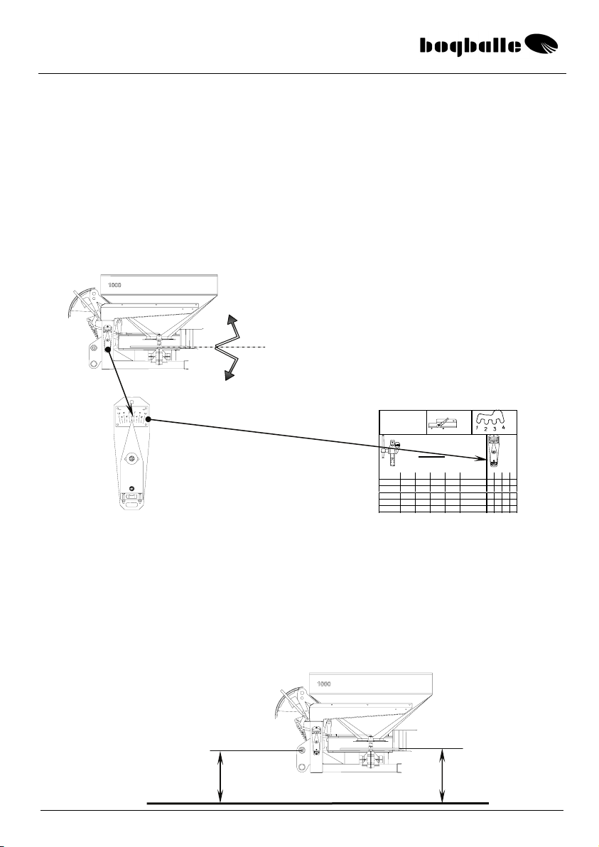
dTILT ANGLE
The machine must be ”tilted” as indicated in the spread chart. The tilt angle is
important for the spread width and is – besides the quantity setting – in reality
the only setting to be done on the machine.
Setting the tilt angle optimizes of the spread pattern – which means in practice
that a minimum variation coefficient (Vk) is achieved.
(See ”Examples of NORMALspread patterns”)
If you doubt, it is better to tilt the machine TOO MUCH – than too little!
In case the fertiliser quantity is changed (±Kg/Ha, for instance with CALIBRATOR or cable
control) – it will not influence the spread pattern seriously.
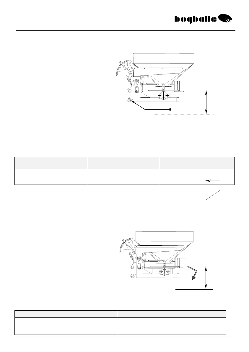
e
WORKING HEIGHT–STANDARD
Mount the spreader horizontally – or tilted
according to the statement in the spread chart
in question.
The tilt angle is adjusted on the top link of the
tractor and the present angle is seen on the
degree meter of the spreader.
+°
-°
Degree meter
Alternatively:
Distance from the upper
side of the spreading disc
– in horizontal position –
to ground: 75 cm.
75 c
m
73 cm
Distance from the centre of the
upper link pins – to the ground:
73 cm.
Ground surface
Spread chart
The pointer of the degree meter is set
to the tilt angle stated in the spread
chart.
Afterwards the machine is tilted by
adjusting the top link of the tractor –
until the level of the degree meter is in
the centre.
The setting is done with the tractor
parked on level ground.
EX(W)
Trend
15
f
WORKING HEIGHT – LATE APPLICATION
The spreader must be tilted when used for late application – dependant on the
distance between the crop top and the spreading discs: A
The chart below indicates the correction to be made – in relation to the tilt angle of
the spreader for NORMALspreading, and according to the chart.
Spread width A = 15 – 35 cm.
Tilt addition (°)
A = 35 – 55 cm.
Tilt addition (°)
15
-
-
12
36
metres
metres
+ 4°
+ 3°
+ 3°
+ 2°
Example:
Tilt angle during NORMALspreading (15-36 metres) according to spread chart = +2°
Hight above crop (A) = 45 cm
Tilt angle during LATE APPLICATION = ( +2°+2°) = + 4°
g
WORKING HEIGHT – CHASSIS KIT
The below chart indicates the correction to be made – in comparison to the tilt
angle of the spreader during NORMALspreading according to spread chart.
Spread width Tilt- reduction (°)
15
18
-
-
-
12
16
36
metres
metres
metres
- 2°
- 1°
No correction
Options are not necessary for
late application in high crops.
•The link pins of the spreader
are moved to the lowest
position in order to lift the
machine as much as possible.
This will minimize the risk of
damage to the crop.
A
Crop top Link pins
If the spreader is mounted on a
chassis kit – the height is
increased from 75 cm to 100 cm
above the ground.
100 cm
Ground -°
EX(W)
Trend
16
24 – 305
E-2 1-2
Kg/ Ha
Km/h
Kg/min
±cm
8101214
1,0 24 19 16 14 7,7 3 4
1,5 53 42 35 30 16,9 3 4
2,0 94 75 63 54 30,1 3 4
2,5 147 118 98 84 47,1 3 4
3
,
0206 165 137 118 66,0 2 3
Såtabel
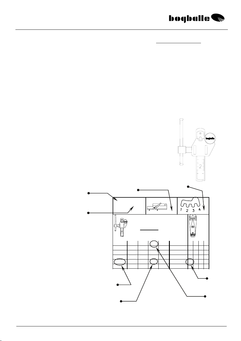
h
*
&
QUANTITY SETTING, Spread chart / Internet: www.bogballe.com
If case the machine is not equipped with CALIBRATOR, the quantity setting is made
on the basis of the instructions in the spread chart.
It must be noted that the spread chart is only a guide, because the quantity spread
depends on the exactness of the driving speed and the tramline distance, but also of
the quality of the fertiliser in question.
The fertiliser will change character according to temperature, air humidity and often
varies with each delivery.
If an exact quantity is required (Kg/Ha), it is recommended to CALIBRATE the
machine by use of the BOGBALLE rate check kit. (See the paragraph ”USE OF RATE
CHECK KIT”)
*
Refer to the appropriate chart for the material to be spread for the settings required.
Spread chart
Vane type
Scale
setting
Chart
number
Vane
position
Tilt
angle (°)
Kg/Ha
Km/h
NB !
Vane type:
E-1 corresponds to E1 T (L/R)
E-2 corresponds to E2 T (L/R)
E-6 corresponds to E6 T (L/R)
Spread
width
The quantity (Kg/Ha) is set by the setting handle of the
machine.
The setting system is equipped with a scale and a scale stop
with stepless movement – and fixed in the inverval from 0 to 9
and with ”marks” for each 0,25 scale step.
The example shows the scale stop set to ”0”, corresponding to
a closed outlet of the machine.
Example: 12 Km/h
Scale = 2,5
98 Kg/Ha
Til
t
=
3
°

EX(W)
Trend
17
iVANE / SPREAD WIDTH Setting U- cut
&The spreading vanes are made in such a way that they are mounted in POS. 1-2, no matter
which type of fertiliser is used – and no matter which quantity is spread. This means in practice
that the spreading vane should only be ”moved / demounted” in case a calibration or emptying
of the hopper is made.
*Take care that the vanes are mounted and fixed correctly !
The vanes are TYPE- MARKED respectively:
”R” (Right) For right spreading disc – seen from behind
”L” (Left) For left speading disc – seen from behind
E( )T-R
E( )T-L
&The vane TYPE is chosen in relation to the required spread width. The vanes are developed in
such a way that only three diferent vane types are covering spead width from 12 to 36 metres.
Below is shown spread width / vane type for the main fertiliser types in the market.
If there are deviations from this it will appear on the spread chart in question.
VANE TYPE SPREAD WIDTH MARK
Trend (Normal / headland vane) E1T 12 – 18 metres E1T R or L respectively
Trend (Normal / headland vane) E2T 20 – 24 metres E2T R or L respectively
Trend (Normal / headland vane) E6T 28 – 36 metres E6T R or L respectively
The vanes are mounted as standard in POS. 1-2
When mounting the fixing bolt must be pulled fully out into the
U-shaped cut before tightening the nut.
If in special cases it is
necessary to mount the
vanes in an alternative
position – this will
appear from the spread
chart in question.
&
POS.- guidance is
shown on a label
fixed to the machine.
POS. 1 - 2
H (R)
V (L)
Vane ”TYPE”
One vane in POS. 1
One vane in POS. 2 On each spreading disc

EX(W)
Trend
18
FUNCTION OF SPREADING VANE
The spreading vane is a key part of the machine – for which reason it is very
important to mount the vanes correctly – and that they are intact.
The Trend system is using both sides of the spreading vanes with: FRONT SIDE for
NORMAL- spreading – and in connection with reversing the rotation direction the
BACK SIDE is used for HEADLAND- spreading.
NORMALspreading
&
•The very special shape of the vane ensures that at NORMAL spreading – the
fertiliser is following the total vane length – and 180°overlap is achieved.
HEADLAND spreading
&
At HEADLAND spreading the fertiliser stream passes through the vane – which
reduces the fertiliser speed – therefore the spread width towards headland is
reduced – and adapted to the distance between tramlines and border with 110°
overlap.
*It is very important that the spreading vanes are intact. This means that the vanes
should not be deformed and that no ”holes” are worn.
If there is rust/paint on the surface of the vanes – it will influence the spread pattern.
The fertiliser will grind away the rust – after spreading 100 – 200 Kg.
o
n
NORMALspreading is made with
the FRONT SIDE n– of the
spreading vane – and with the
spreading discs rotating towards
eachother.
(
See next
p
a
g
e
)
HEADLAND spreading is made with the
BACK SIDE oof the spreading vane- and
with the rotation of the spreading discs
away from each other.
(
See next
p
a
g
e
)
This manual suits for next models
1
Table of contents
Other Boqballe Farm Equipment manuals

Popular Farm Equipment manuals by other brands

Schaffert
Schaffert Rebounder Mounting instructions

Stocks AG
Stocks AG Fan Jet Pro Plus 65 Original Operating Manual and parts list

Cumberland
Cumberland Integra Feed-Link Installation and operation manual

BROWN
BROWN BDHP-1250 Owner's/operator's manual

Molon
Molon BCS operating instructions

Vaderstad
Vaderstad Rapid Series instructions


