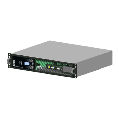
Borri STS-16 User manual

BORRI STS / ITS 16A-32A
USER MANUAL / MANUALE UTENTE
Static Switch
For ICT, infrastructures and services
Commutatore statico
Per ICT, infrastrutture e servizi

USER MANAUL / MANUALE UTENTE
Index Code Page
English Language STS 16A-32A 4
Safety instructions STS 16A-32A 5
Storage instructions STS 16A-32A 6
General characteritics STS 16A-32A 7
Special features STS 16A-32A 7
Functional description STS 16A-32A 8
LCD display STS 16A-32A 9
Back panel STS 16A-32A 10
Interface RS232 STS 16A-32A 11
USB port STS 16A-32A 11
Alarm connector STS 16A-32A 12
STS Installation STS 16A-32A 13
STS supply STS 16A-32A 15
Troubleshooting STS 16A-32A 16
Technical specifications STS 16A-32A 17
Error codes STS 16A-32A 18
Rev. Descrizione
Description
Data
Date
Emesso
Issued
Controllato
Checked
Approvato
Approved
Lingua
Language
Pagina
Page
di Pag.
of Pag.
/ Emissione 28.06.16 V.Bianchi P. Conti P. Conti E/I
2 36
C Aggiornamneto 18.09.17 V.Bianchi P. Conti P. Conti Codice / Code
D VR173-17 04.12.17 V.Bianchi P. Conti P. Conti
OMP68017

Pagina 3 di 36 OMP68017 Rev. D 24/12/17
Indice Codice Pagina
Lingua Italiana
STS 16A-32A
20
Istruzione per la sicurezza STS 16A-32A 21
Istruzione per l’immagazzinamento STS 16A-32A 22
Caratteristiche generali STS 16A-32A 23
Particolarità STS 16A-32A 23
Descrizione funzionale STS 16A-32A 24
Display LCD STS 16A-32A 25
Pannello posteriore STS 16A-32A 26
Interfaccia RS232 STS 16A-32A 27
Porta USB STS 16A-32A 27
Connettore allarmi STS 16A-32A 28
Installazione STS STS 16A-32A 29
Alimentazione STS STS 16A-32A 31
Risoluzione dei problemi STS 16A-32A 32
Specifiche tecniche STS 16A-32A 33
Codici errori STS 16A-32A 34

Pagina 4 di 36 OMP68017 Rev. D 24/12/17
ENGLISH LANGUAGE

Pagina 5 di 36 OMP68017 Rev. D 24/12/17
SAFETY INSTRUCTIONS
IMPORTANT: Safety instructions
This manual contains important safety information. Carefully follow the instructions when
handling, installing, using and maintaining the device. Please read the product manual
carefully before installation.
Keep the instructions.
- Check the device at the time of receipt and report any damage or malfunction to your
dealer. Do not install the device if there are any signs of damage.
- Use a suitable device for handling the device according to its weight and dimensions
Improper use of loads can create risks for the operator.
- Switch off the device and disconnect the power supply and signal connections during
handling.
- Install the device in a closed, dust-protected area. The device is not meant for outside
installation. Ensure that the installation site meets the following environmental conditions:
temperature: 0-40°C, relative humidity 0-90% without condensation.
- Do not expose the device to direct sunlight; do not obstruct the ventilation ducts of the
crankcase. High ambient temperatures can reduce battery life and jeopardize the
operation of the device.
- Do not install the device in places where there are flammable or explosive agents.
- Do not install the device in places where saline or corrosive agents are present.
- The vibrations and impacts can compromise the safety and operation of the device.
Locate a secure site for installation.
- Do not position anything on the device.
- Do not pour liquids into the outer surfaces of the device and in the grooves of the
housing.
- Always disconnect the equipment and check that there are no potential hazards before
carrying out any maintenance work. If the device contains storage devices, input and
output ports may remain energized even after disconnection.
- Always use protective equipment and remove personal items such as bracelets, watches,
and jewels before performing ordinary and extraordinary maintenance. Do not remove
protective covers if not required for maintenance.
- The maintenance operations mentioned in the user manual must be performed by
qualified personnel.
- Repair operations invalidate the warranty. Always contact your dealer or authorized
service centre.
- Make sure that the power supply is earthed and that the electrical characteristics meet
the nominal ratings required for the equipment.
- Make sure that the connecting cables comply with the country's
- Installation standards. Do not use worn or damaged connection cables.
- Do not use the device to supply medical devices whose operation may be hazardous to
the health or life of the patient.

Pagina 6 di 36 OMP68017 Rev. D 24/12/17
STORAGE INSTRUCTIONS
If the static switch is not used for a prolonged period of time, it must be stored at a
moderate temperature and in any case within the range of temperature and humidity
expected and indicated in the device's technical specifications.

Pagina 7 di 36 OMP68017 Rev. D 24/12/17
GENERAL CHARACTERISTICS.
The system called STS (Static Transfer Switch) has two independent input sources,
Source A (LINE 1) and Source B (LINE 2). Outputs are connected to the loads which, in
normal operation, are powered by the supply source A
If the source A voltage is missing or is out of range, the system automatically switches the
loads to source B. The STS returns to supply the loads through Source A as soon as this
return is available.
SPECIAL FEATURES
1. Our high frequency power drive technology allows for greater integration of the
SPS, enabling it to be used even in enclosed environments.
2. The totally digital control system (DSP) of the SPS allows you to enhance the
functionality and high level of protection of the machine itself. The powerful
communication port enhances the remote control and supervision of the SPS.
3. The large input voltage tolerance (110-300 Vac) allows the use of the SPS in
critical power situations.
4. The integration of the STS with the ITS allows, in case of anomalies, a rapid
replacement of the device without interruption.
5. The STS is designed to comply with the various international standards on
electromagnetic interference compatibility (EMC).
Input
Input
Output
load
LINE 1
LINE 2
LOAD

Pagina 8 di 36 OMP68017 Rev. D 24/12/17
FUNCTIONAL DESCRIPTION.
Front view.
No.
Key Description
1. Buzzer Silence the buzzer (triggered by an
alarm)
2. Source selection button
It is possible to display the
information on: Source A, Source B,
Load
3. Information selection button
Select the source and it is possible to
display: Voltage, Current, Frequency,
Output Load
4. Input switch button Switch between sources: Source A
Source B
5. LCD Display
6. Alarm presence LED On:
system malfunction
Off: correct system operation
7. Source B Indicator LED
On:
voltage and frequency standard
Off: voltage and frequency not
standard
Flashing : Priority source
8. Source A Indicator LED
On:
voltage and frequency standard
Off: voltage and frequency not
standard
Flashing : Priority source
9. USB port Connection for setup software or
monitoring software
10. RS-232 Port Connection for setup software or
monitoring software
11. External contacts port External contacts
12. External communication slot External communication card slot

Pagina 9 di 36 OMP68017 Rev. D 24/12/17
LCD DISPLAY
Symbols
Description
Source A error
Source B error
Overload
Alarm
Buzzer off
Display the source that supplies the load
Numeric display

Pagina 10 di 36 OMP68017 Rev. D 24/12/17
BACK PANEL
Shown below is the back of the device with the basic preliminary
Information (It will be revised)
STS / ITS – 16 (230V – 16A)
1. LINE B Input
2. LINE A Input
3. Output (NO to the left, LO to the right, PE to the top in the middle)
4. Line A Line B Switch (A/B). Manual Use line selection.
5. Manual Automatic Switch(A / M)
STS / ITS – 32 (230V – 32A)
1. Input/output connector (LB, NB,)
2. Input/output connector (LA, NA, PE)
3. Input/output connector (PE, LO, NO)
4. Line A Line B Switch (A/B). Manual Use line selection.
5. Manual Automatic Switch(A / M)
STS – 32 (230V – 32A)
1. Input and Output Connector
2. IEC Output sockets

Pagina 11 di 36 OMP68017 Rev. D 24/12/17
INTERFACE
The STS is equipped with three communication ports and one optional external
communication port.
RS-232 PORT
USB PORT
Pin
Definition
Type
Signal
1 N/A N/A N/A
2 TX Output
TX
3 RX Input RX
4 N/A N/A N/A
5 GND Earth N/A
6 +12 V Signal
N/A
7 N/A N/A N/A
8 N/A N/A N/A
9 N/A N/A N/A
Pin
Signal
1 VBUS
2 D -
3 D +
4 GND

Pagina 12 di 36 OMP68017 Rev. D 24/12/17
ALARM CONNECTOR
The STS is equipped with 5 configurable clean contacts. Each contact is made up of one
24Vdc/1A relay, to see the complete alarm list, refer to Appendix A.
Pin
Definition
Default Signal
1 Common 3
N/A
2 Relay 3 General alarm
3 Relay 4 Overload
4 Common N/A
5 Relay 5 High temperature
6 Common 1
N/A
7 Relay 1 Fault Source A
8 Common 2
N/A
9 Relay 2 Fault Source B
COMMON 1
COMMON 2
COMMON 3
COMMON
RELAY 1
RELAY 2
RELAY 3
RELAY 4
RELAY 5

Pagina 13 di 36 OMP68017 Rev. D 24/12/17
STS INSTALLATION
1) On receipt of the goods, check the packaging. Any missing content, damage or
other problems must be reported to the shipping company or to the dealer as soon
as possible.
2) Check that the device received is actually what was requested in your order
3) Place the STS inside the frame.
4) Connect the loads to the output sockets of the STS, if possible distribute them
evenly.
5) Check that all parameters are within the specified limits.
6) Check that the maximum load does not exceed the product specifications.
STS/ITS

Pagina 14 di 36 OMP68017 Rev. D 24/12/17
STS

Pagina 15 di 36 OMP68017 Rev. D 24/12/17
STS SUPPLY
As soon as a source is connected, the STS will turn on automatically. The LCD will turn on
as shown in the left figure and the LEDs will light up.
After the start-up, the display is as shown in the right figure, and the LEDs for Sources A
and B light up.
SWITCH BETWEEN SOURCE A SOURCE B
The ATS supports manual control for switching between source A source B.
Press the button for 2 seconds until you hear 2 consecutive “beeps”.
The system requires confirmation of the switching of the supply (LCD will show on the LCD
as shown in Figure 1), to confirm, press the button again for 2 seconds, the LCD
display will display the new source that powers the output (Figure 2). If the output is not
available, the display will display an alarm and the switch of supply will not occur.
Figure 1 Figure 2 Figure 3

Pagina 16 di 36 OMP68017 Rev. D 24/12/17
TROUBLESHOOTING
If your STS system does not work properly or you are having problems, check the guide
below. If the problem persists, please contact your local supplier for assistance.
Problem
Possible cause
Solution
ATS off
Electrical connection not
present
Check the electrical
connection to the STS input
Connection values off-
specification
Get assistance from a
professional electrician
Input Breaker tripped Reset Breaker input
Damaged internal
components Contact your supplier
Power supply but display
turned off
Damaged internal
components Contact your supplier
Error Code:
Er01; Er02
No network connection Check the connection
values to the STS input
Connection values off-
specification
Get assistance from a
professional electrician
Error Codes:
from Er03 to Er15
Incorrect power supply
system
Get assistance from a
professional electrician
Error Code: Er16 overload Check the load
Error Code:
from Er17 to Er32
Non-compliant internal
components Contact your supplier

Pagina 17 di 36 OMP68017 Rev. D 24/12/17
TECHNICAL SPECIFICATIONS
TYPE/MODEL
STS - 16
STS - 32
INCOME PARAMETERS
Mains voltage 200V / 208V / 220V / 230V / 240V
(can be set via software: +/- 5%, 10%, 15%, 20%)
Voltage range 150Vac~300Vac
Input frequency 50/60 Hz (can be set via software: +/- 5%, 10%, 15%,
20%)
Input current. 16 A 32 A
OUTPUT PARAMETERS
Output voltage 200V / 208V / 220V / 230V / 240V
Output Current 16 A 32 A
Overload
101-110% Pre-alarm
110-125% 1min.
125-150% x 30sec.
150-200% 5 sec.
> 200% x 1 sec.
101-110% Pre-alarm
110-125% 1min.
125-150% x 30sec.
150-200% 5 sec.
> 200% x 1 sec.
CONNECTIONS
Input Connections IEC-C20 x2 Terminals for 40 A x 6
Output Connections IEC-C13 x 8,
IEC-C19 x 1
IEC-C13 x16,
IEC-C19 x2
Protections Input Switch (Optional)
Electronic protection system
Communication RS-232, USB, clean contacts,
Optional card Slot (SNMP, RS-485)
Switching time in phase
(ms) 2 – 6 ms
Efficiency 98.2% (at full load)
Display LCD + LED
DIMENSIONS:
W x L x H (mm) 275 x 440 x 88 275 x 440 x 88
Weight (Kg) 6 6
ENVIRONMENTAL PARAMETERS
Operating temperature -5 ÷ +40 °C @ 20~90% RH

Pagina 18 di 36 OMP68017 Rev. D 24/12/17
ERROR CODES
EVENTS
CODE
1 Source A not connected Er01
2 Source B not connected Er02
3 Incompatible source A
voltage Er03
4 Incompatible source B
voltage Er04
5 Incompatible source A
frequency Er05
6 Incompatible source B
frequency Er06
7 Incompatible source A
frequency and voltage Er07
8 Incompatible source B
frequency and voltage Er08
9
ATS output not present
source causes non-
conforming source A and B
parameters
Er09
10 Unbalanced source A
voltage Er10
11 Unbalanced source B
voltage Er11
12 Unbalanced ATS output
voltage Er12
13 Incompatible ATS output
voltage Er13
14 Incompatible ATS output
frequency Er14
15 Incompatible ATS output
voltage and frequency Er15
16 ATS output in overload and
output disconnected Er16
17 Output short circuit to the
AT and output disconnected
Er17
18 Input of source A faulty Er18
19 Input of source B faulty Er19
20 Er20
21 ATS output faulty Er21
22 Incompatible 12V internal
voltage for source A Er22
23 Incompatible 12V internal
voltage for source B Er23
24 High temperature Er24
25 Internal DC voltage error Er25
26 Eeprom error Er26

Pagina 19 di 36 OMP68017 Rev. D 24/12/17
27 Emergency shut-down Er27
28 LCD not connected Er28
29 Overload time out Er29
30 Transferring fail by sync
setting condition Er30
31 Pre-alarm active Er31
32 Communication connection
abnormal ER32

Pagina 20 di 36 OMP68017 Rev. D 24/12/17
LINGUA ITALIANA
This manual suits for next models
1
Table of contents
Languages:
Other Borri Switch manuals
Popular Switch manuals by other brands

US Robotics
US Robotics USR997933 Specifications

Halma
Halma FORTRESS am Gard S40ST401 operating instructions
Fermax
Fermax BUS 3 Wiring diagram
US Robotics
US Robotics 005687-03 - reference guide
Intellinet
Intellinet 560801 Quick install guide
Siemens
Siemens SIRIUS 3SE53 Series Original operating instructions
