Borroughs WILSONSTAK User manual
- 1 -
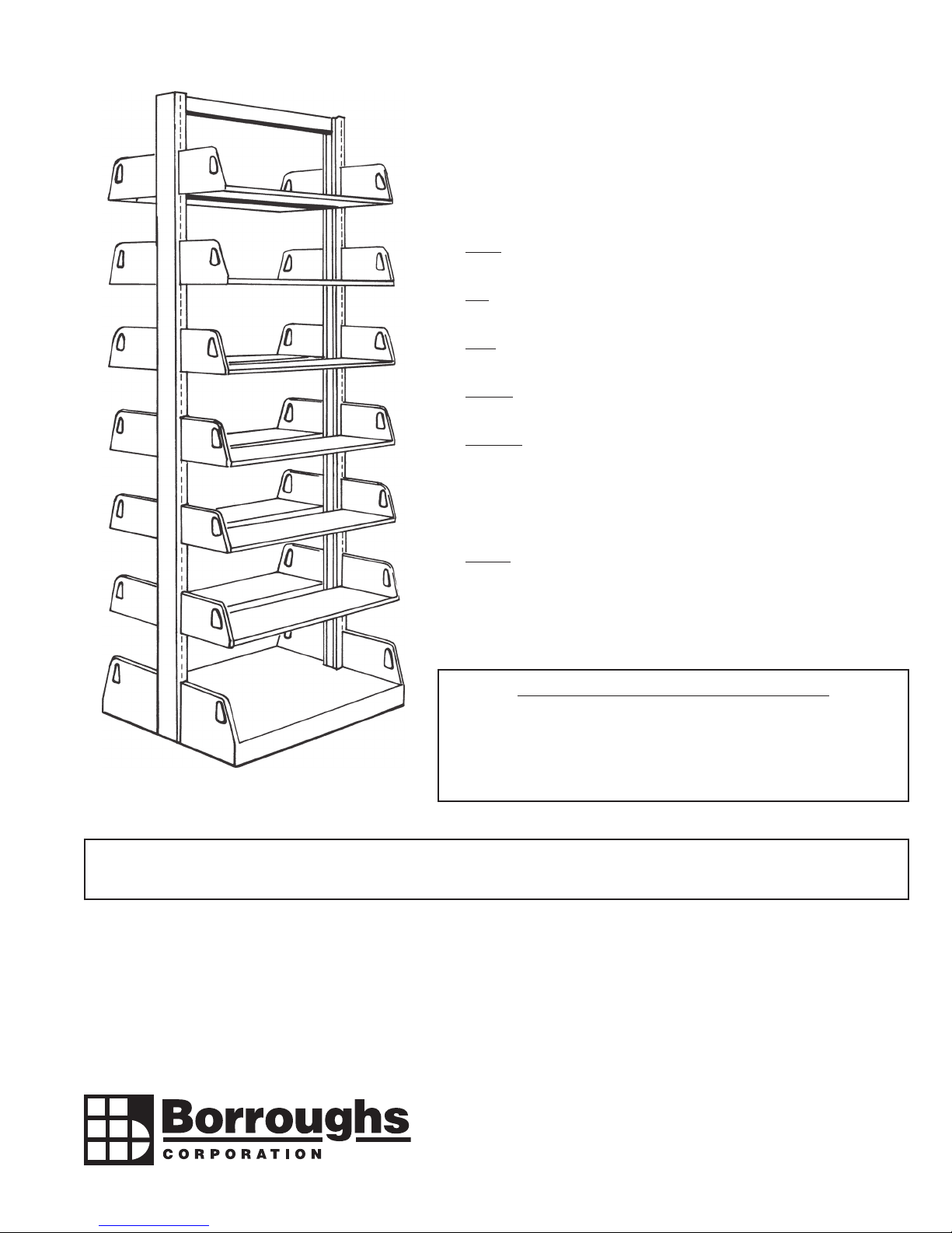
WILSONSTAK LIBRARY and
CANTILEVER RECORD MASTER.
INSTALLATION INSTRUCTIONS
GENERAL INSTRUCTIONS:
1. Check parts and bundles against packing slip to be sure all parts and bundles
were received.
2. Sort parts so that like parts are together. This will make installation easier and
faster.
3. Read through the entire instructions carefully - before attempting to assemble
the units. Units must be level.
4. Leveling - Units must be leveled (page 3). Each type of welded frame requires
a different procedure for leveling.
5. Anchoring - Important to prevent tip over of units. Read and follow instruc-
tions for anchoring. Anchoring must conform to building conditions and local
codes. Anchoring varies depending on heights and types of frames. All single
face units require wall anchoring, or oor anchors and top tie struts. All units 78"
and higher where adjustable shelves are vertically ush with base shelf require
oor anchors or top tie struts. (pages 5, 6 and 13).
6. Loading - To ensure unit stability, units must be loaded starting at the base and
working up. Double face units should be loaded on both sides equally starting
at the base and working up.
WARRANTY
Borroughs Corporation extends to the original purchaser from the date of purchase a ve-year limited warranty against manufacturing defects in material and workmanship. If a Borroughs
product fails to perform because of a manufacturing defect, Borroughs will examine it. If found defective, it will be repaired or replaced at our option. This warranty does not apply to
any product which has been subject to misuse, negligence, or accident; has been damaged in shipment, storage, or installation; has been misapplied or has been modied or repaired
by unauthorized persons or been repaired with non-standard Borroughs replacement parts. This warranty specically excludes claims for indirect, incidental, or consequential damages
arising in any way from a product defect. This warranty is exclusive, and exists in lieu of all other warranties, either expressed or implied. To obtain warranty service, contact your Bor-
roughs Selling Dealer. You must make a written claim. Provide a copy of your purchase record and a written description of the warranty problem with your claim. If you are unable to
contact your Dealer, contact: Borroughs Corporation, Customer Service Manager, 3002 N. Burdick St., Kalamazoo, MI 49004-3483.
IMPORTANT - PRODUCT LIABILITY INFORMATION
Read all instructions before proceeding with assembly. Vital product
information pertaining to proper set-up and cautions are included.
Failure to follow these instructions may result in personal injury and/or
property damage.
IMPORTANT NOTICE - At no time should personnel be allowed to climb or stand on shelving product. Safe access to all shelving levels
should be provided with ladders and/or other devises which are in accordance with applicable OSHA regulations.
3002 N. BURDICK STREET KALAMAZOO, MI 49004-3483
800-748-0227 FAX: 269-342-4161 www.borroughs.com
50-50424-000D
November 2016
®
®

- 2 -
STANDARD WELDED FRAMES
Standard welded frames are furnished
with two adjustable leg levelers and two
snap t cap oor glides. Carpet pins can
be substituted for levelers when specied.
See page 4 for details.
WELDED FRAMES WITH LEVELERS
1. Assemble snap t cap to hex head of 3/8-16 x 1-1/2" leg leveler bolt. See Figure 1. (Snap
t cap prevents bookstack units from creeping on a smooth-surfaced oor and can be
eliminated if used on a carpeted surface).
2. Screw leg levelers into weld nuts in bottom rail of each welded frame as shown in Figures
2, 3 and 8. Screw leg levelers all the way in.
3. Stand frame upright and snap a base bracket assembly into place on the inside of frame
uprights and as low as possible. (Frame should stand upright alone at this point). See
Figure 4.
NOTE:
a) Single face units have left-hand and right-hand base brackets. Double face units have
base brackets that may be used on either end.
b) Finished end brackets, if furnished, are installed on exposed ends of unit ranges.
4. Position the frame set-ups in range rows. Fasten frame uprights together, starting with the
top joining holes provided in the frame upright web, using 1/4-20 x 5/8 Phillips pan head
machine screws and 1/4-20 Keps nuts. Visually check that the slots in the adjoining frames
line up with each other.
Do not bolt through base brackets at this time. See Figure 5.
FIGURE 1
FIGURE 2
FIGURE 3
FIGURE 4
FIGURE 5
FIGURE5
00954-30
00954-70
00954-30
13974-00
07742-00
STANDARD INSTALLATION

- 3 -
LEVELING
5. After all frames are joined in a range, stretch a nylon line from one
end of the range to the other end, at eye level. Adjust leg levelers
so that they are all bearing on the oor surface and slots in the
frame uprights are in line horizontally across face of range.
6a. Install balance of base brackets. Force base bracket down to oor
surface. (Base brackets have a 3/4" adjustment allowance built
in). Secure base brackets and the uprights with two (2) 1/4-20
x 3/4 Phillips truss head machine screws and two (2) 1/4-20
hex nuts. See Figure 6.
6b. Secure each base bracket to face of upright on both sides with
#10 x 5/8 pan head sheet metal screws. See Figure 6.
IMPORTANT NOTE: Base brackets must be ush to oor to ensure
unit stability and secured with sheet metal screws to prevent bracket
from working up frame when loaded.
7. Secure base brackets together with a 1/4-20 x 3/8 Phillips pan head
machine screw and a 1/4-20 hex nut through hole at front of base
bracket in bracket depression. See Figure 7.
NOTE:
a. It is not necessary to tighten nut and bolt beyond binding point
since there is no load bearing at this point.
b. The nut and bolt should not protrude beyond the depression
of the bracket as book damage could result.
c. Anchoring - requirements for anchoring units to oors and
walls should be reviewed and followed. See pages 5, 6 and 13.
8. Install base shelves. See page 8.
FIGURE 6
FIGURE 7
ADJUSTABLE LEG LEVELER INSTALLATION
FIGURE 8
ADJUSTABLE LEG LEVELER INSTALLATION
FIGURE 8
FIGURE 6
FRAMES ARE NOW READY TO RECEIVE BALANCE OF COMPONENTS.
FIGURE 7
07742-00
14993-00
00950-15
07742-00

- 4 -
CARPET PI N INSTALLATION
FIGURE 10
WELDED FRAMES WITH CARPET PINS
1. Insert carpet pins into clip nuts in bottom rail of welded frame as shown in Figures 9A and 9B. Screw into threads only enough to rmly engage
nut with pin.
2. Proceed as in Steps 2 through 7 on pages 2 and 3 - WELDED FRAMES WITH LEVELERS.
3. Insert carpet pins into base brackets. See Figures 9 and 10. Adjust carpet pins so that columns are plumb and all pin surfaces bear on carpet.
4. Install base shelves. See page 8.
FRAMES ARE NOW READY TO RECEIVE BALANCE OF COMPONENTS.
CARPET PIN INSTALLATION
FIGURE 10
MUST BE SPECIFIED AS 4-POINT LEVELING SYSTEM
CARPET PINS MUST BE ORDERED SEPARATELY
FIGURE 9A
FIGURE 9B
00954-20
00954-20
00956-16
Clip Nut
00956-16
00954-20 00954-20
00954-20
00956-16
OPTIONAL INSTALLATION (ADDITIONAL COMPONENTS REQUIRED)

- 5 -
WALL ANCHORING
1. Wall anchor angles are provided with each single faced unit for securing
to wall.
2. Fasten wall anchor angle to upright of frame by using a tie-down clip and
a 1/4 x 5/8 Phillips pan head sheet metal screw. See Figure 11.
3. Unit is now ready to be secured to wall using lag or anchor of the installer's
choice.
CAUTION: All singe faced units must be anchored. Single face units are
not recommended for free-standing units. When used where wall anchoring
is not applicable, single faced units must be oor anchored. Units over 78"
high should be oor anchored and top tie strutted.
CLOSED BACKS ON WALL ANCHORED UNITS
Read and review installation instructions on page 8 for installation of backs
into units.
1. Assemble range of units with base brackets and set range against wall
where units are to be anchored.
2. When backs are required, wall anchoring can be accomplished in two
ways:
a. With angle against wall and "L" portion over top of upright.
b. With angle against wall and "L" portion over top of top horizontal
member of frame.
3. Level units along range length by adjusting leg levelers and bolts attach-
ing units together.
4. Mark anchor locations on wall.
5. Step units away from wall and install backs. Backs are to be placed with
the ush side facing toward the base brackets. See Figure 20B on page
8 of this instruction manual.
6. Install wall anchor angle onto wall at marked locations.
7. Replace units against wall. Re-adjust levelers as necessary.
8. Attach angles to frames from the top down with a self-drilling screw (not
provided). See Figure 12.
9. Install remaining components as required for specic application.
FIGURE 11
FIGURE 12
FIGURE 12
FIGURE 11
31382-50
00953-10
00951-20
31382-50
(NOT INCLUDED)

- 6 -
FIGURE 13
FIGURE 14
FLOOR ANCHORING
It is the responsibility of the user and installer to provide for
proper anchoring of shelving sections. Anchoring to any
part of the building structure requires that the local building
codes be met.
1. Make sure shelving range is in line and that the base
brackets are securely fastened to frames.
2. Plumb frames by using shims, as necessary, under
base brackets.
3. Drill into oor using holes in base brackets as a tem-
plate.
4. Install anchoring device (not provided) of the installer's
choice or as required for the particular oor condition.
See Figure 14.
TRIANGULAR GUSSETS (optional)
1. Before joining welded frames side-by-side, sandwich triangular gussets between frames
and base brackets and fasten with 1/4-20 x 1/2 Phillips pan head machine screws. See
Figure 13.
2. Plumb uprights by installing shims under either side of gusset.
3. Secure welded frames together with 1/4-20 x 1/2 Phillips pan head machine screws
and 1/4-20 x 5/8 Phillips pan head machine screws with 1/4-20 Keps nuts as shown.
See Figure 13.
FIGURE 14
00950-10
13974-00
07742-00
(NOT INCLUDED)

- 7 -
T-BAR LEG BASE FRAME
NOTE: Applies to either leg leveler or carpet pin installation.
1. Assemble snap t cap to leg levelers (see Figure 1, page 2). Screw leg levelers or
carpet pins into T-bar leg base in holes provided. See Figure 16. Screw leg levelers
up against bottom of base. (If carpet pin is used, insert as far up as possible without
disengaging threads).
2. Assembling frames and leg bases. See Figures 15 and 17.
a. Install frame extension over T-bar upright as shown in Figure 17 and fasten with
1/4-20 x 3/4 Phillips truss head machine screws and 1/4-20 Keps nuts.
b. Install opposite extension of frame plus an extension of the adder frame into the
next T-bar upright and fasten with 1/4-20 x 3/4 Phillips truss head machine screws
and 1/4-20 Keps nuts. Continue to end of range.
3. Proceed to level and plumb frames to vertical and horizontal (see Step 5 on page 3).
Adjust levelers or carpet pins with screwdriver and install button plugs into adjustment
holes. See Figures 17 and 18.
4. Install ller channels at ends of ranges as required. Completed assembly shown in
Figure 18.
FRAMES ARE NOW READY TO RECEIVE BALANCE OF COMPONENTS.
FIGURE 15
FIGURE 16
FIGURE 17
FIGURE 18
00954-30
00954-20
00954-40
14993-00
07742-00

- 8 -
BASE SHELF - SINGLE or DOUBLE FACED
1. Place base shelf between base brackets tilted at a slight angle.
Carefully align shelf notch with upright to avoid scratching. See
Figure 19.
2. Lower opposite side in place exercising care not to scratch paint.
Once shelf is parallel, tap edges into tabs in base bracket.
NOTE: When properly installed, base shelf will follow brackets to the
oor and will overlap base bracket edges to give a continuous appear-
ance along front.
FIGURE 19
CLOSED BACKS
NOTE: If closed back is used, it should be installed after the base shelf
and before any other shelves are set into place.
1. Snap a closed back channel inside the open side of each upright
of the frame. See Figure 20A.
2. The closed back will t between the uprights, top rail and base shelf
from the back side of the unit. Align holes in closed back with those
in closed back channel and fasten with #10 x 5/8 Phillips pan head
sheet metal screws. See Figure 20B.
FIGURE 20A FIGURE 20B
16118-00

- 9 -
STEEL CANOPY TOPS
1. Install canopy brackets in the top slots
of the frame uprights. See Figure 21.
2. Single Frame Assembly:
Set canopy top over the frame with the
brackets on the outside of canopy top.
Secure with 1/4-20 x 1 Phillips truss
head machine screws and 1/4-20 hex
nuts.
3. Multiple Unit Assembly:
If units are side-by-side, bolt through
both canopy tops and brackets using
1/4-20 x 1 Phillips truss head machine
screws and 1/4-20 hex nuts.
SHELF END BRACKETS
NOTE: Shelf end brackets are formed opposite. There are left-hand
and right-hand brackets.
1. Place shelf end brackets in slots of frame - ange out and tabs in.
See Figure 22.
2. Make sure that both end brackets are at the same height from the
oor.
3. If nished shelf end brackets are furnished, follow the above pro-
cedures with nished brackets installed on ends of range only.
NOTE: Left-hand end bracket shown in Figure 22.
ADJUSTABLE or DIVIDER SHELVES
1. Hardware not required. Place the adjustable or divider shelf
between the end brackets, with the side anges of the shelf tting
behind the tabs in the brackets. Tap shelf down, by hand, to be
sure that the shelf is securely in place.
2. Shelves are now fully adjustable and can be easily located where
required. See Figure 23.
CAUTION: When end panels are used, use care when adjusting shelves
so as not to scratch end panels.
FIGURE 23
FIGURE 22
FIGURE 21
07789-00
07742-00

- 10 -
FIXED PERIODICAL SHELF
1. Secure the xed periodical shelf to xed
periodical end brackets with #10-24 x
3/8 Phillips truss head machine screws
and #10-24 hex nuts.
2. Set assembled shelf on uprights of
frame by tting tabs of the brackets
into slots of the frame upright.
- 10 -
FIGURE 24
FIGURE 24
FIGURE 25
STORAGE SHELF
1. Canopy top brackets are used to sup-
port the storage shelf. Set canopy top
brackets into slots in uprights of frame
at equal distance from the oor.
2. Set the storage shelf on the brackets,
with the brackets inside the shell
anges. Secure the storage shelf to
the canopy top rackets using 1/4-20 x 1
Phillips truss head machine screw and
1/4-20 hex nuts. See Figure 25.
- 10 -
FIGURE 25
07732-00
07784-00
07789-00
07742-00

- 11 -
FIGURE 26A
HINGED PERIODICAL SHELF
1. The hinged periodical shelf end bracket is similar to a regular adjustable shelf end bracket except a pivot hole has been punched into it. See
Figure 26A.
2. Assemble an adjustable shelf as outlined in section ADJUSTABLE or DIVIDER SHELVES on page 9 using hinged periodical end brackets.
3. There are four (4) holes provided in the face of the shelf pan (at each end) so that 12" or 16" deep shelves may be used. Pivot brackets for
12" and 16" shelves are different. (Check size of bracket if shelf does not balance properly after assembly).
4. Place hinged periodical shelf pan over narrow ange of pivot bracket and align holes. See Figure 26B.
NOTE:
a. The rst and third holes from the top of shelf pan are used with 3" pivot bracket and 12" adjustable shelves.
b. The second and fourth holes from top of shelf pan are used with 6" pivot bracket and 16" adjustable shelves.
5. Fasten pivot brackets to hinged periodical shelf pan with #10-24 x 3/8 Phillips truss head machine screws and #10-24 hex nuts.
6. Align holes in pivot brackets with 1/4 at washers and holes in hinged periodical shelf end brackets and fasten with 1/4-20 x 5/8 pan head
screws and 1/4-20 Nyloc nuts. Head of screw should be on outside of bracket and Nyloc nut toward inside of shelf. See Figure 26A.
NOTE: Hinged periodical base shelves - install screws in base shelf end brackets before installing base shelves.
7. Install bumpers at each end of top ange on shelf pan and on back bottom corners.
- 10 -
FIGURE 26B
FIGURE 26B
- 10 -
FIGURE 26A
17415-00
42690-00
00951-20
07849-00
07784-00
07732-00

- 12 -
HINGED PLEXIGLASS COVERS
NOTE: Complete the assembly of the hinged periodical shelf before installing
the plexiglass covers.
1. Installation is the same for both the one-piece and the two-piece covers.
See Figure 27A.
2. Hinged periodical shelves are provided with the piano hinges welded
on.
NOTE: Steps 3 and 4 below can be replaced by using double-sided tape on
the underside of the hinge to fasten plexiglass cover. Tape not included.
3. Center plexiglass sheet under hinge. Using pre-drilled holes in hinge as
a template, drill holes through plexiglass cover.
4. Pop rivet the cover in place through the hinge, plexiglass and #10 at
washer with a 3/16 Lo-pro pop rivet. See Figure 27B.
FIGURE 27A
FIGURE 27B FIGURE 27C
FIGURE 28A FIGURE 29
DETAIL
FIGURE 28B
WALL HUNG COLUMN STRIPS - use instead of welded frame against wall
1. Lag or anchor the column strip where required; normally 36" on center. See Figures 28A, 28B and 29.
2. Be sure the column strip is plumb and that the tops are level. Lags and anchors are not supplied and must meet local building codes. See
Figures 28A and 29.
14251-00
07884-00

- 13 -
TRANSVERSE TOP STRUTS
1. Top struts are used with non-freestanding and open-base bookstacks to tie units together and add stability. See Figure 30.
2. Top struts are fabricated with different dimensions on each end. Insert narrow end of one into wider end on the next top strut. See View Z-Z.
Use one (1) 1/4-20 x 3/4 Phillips truss head machine screw and one (1) 1/4-20 hex nut to secure top struts together.
3. Use two (2) #10 x 5/8 sheet metal screws to secure transverse top struts to the top rail of welded frame. See Figure 30.
FIGURE 30 VIEW Z-Z
SLIDING REFERENCE SHELF
NOTE: Sliding reference shelves should be located at a convenient working height or positioned to suit conditions of assembly. The slides and
housings are pre-assembled and attached to the reference shelf.
1. Place an adjustable or divider shelf between two shelf end brackets with the side anges of the shelf tting behind the tabs in the brackets. Tap
down the shelf, by hand, until the shelf is securely in place. (Reference Steps 1 and 2, Figure 23, page 9).
2. Attach the slide housing to a right and left hand shelf end bracket through holes in end bracket tabs using 1/4-20 x 5/8 Phillips pan head machine
screws and 1/4-20 Keps nuts.
3. Reference shelf assembly is now ready to be installed into slots of frame uprights at desired location and height.
FIGURE 31
16118-00
14993-00
07742-00
13974-00
07742-00

- 14 -
DIVIDERS
1. Dividers are set in shelf by rst hooking the front hook of divider into the slot at the
front of the shelf. See Figure 32.
2. Then, insert rear hook of the divider into the slot in the divider shelf back stop. Tab at
the back of the divider should fall into the slot at the back of the shelf as shown.
FIGURE 32
FIGURE 32
STEEL END PANELS (Closed Base)
SINGLE FACED END PANELS
1. Stand end panel against welded frame and
attach to the upright with 1/4-20 x 3/4 Phil-
lips pan head machines screws and 1/4-20
Keps nuts. See Figure 33.
2. Secure end panel to base bracket with a #10
x 5/8 Phillips pan head sheet metal screw.
(Reference Figure 35).
FIGURE 33
FIGURE 33
DOUBLE FACED END PANELS
1. Align end panel ller channel with welded frame upright. See Figure 34A. Attach panel to upright with 1/4 x 5/8 Phillips pan head sheet metal
screws and tie-down clips – two (2) each for units 66" and three (3) each for units 66" and higher.
2. Secure end panel to base bracket with #10 x 5/8 Phillips pan head sheet metal screws. See Figure 35.
3. If canopy top and brackets are used, attach canopy top and brackets to end panel with 1/4-20 x 1 Phillips truss head machine screws and 1/4-20
hex nuts (hardware not shown in Figure 35).
FIGURE 34A
FIGURE 34B
FIGURE 35
FIGURE 34A
FIGURE 34B
FIGURE 35
07742-00
14993-00
00951-20
00953-10
00953-10
00951-20
16118-00
00951-20
Truss

- 15 -
LAMINATED or WOOD END PANELS
DOUBLE FACED END PANELS
1. Stand end panel against welded frame and center over
frame upright. Using holes in web of frame, attach wood
panel to frame with wood or sheet metals screws. Screws
not provided. See Figure 36.
2. Attach end panel at top through canopy top bracket holes.
Screws not provided.
3. Attach panel at bottom through holes provided in depression
of base bracket. Screws not provided. See Figure 36.
FIGURE 36
FIGURE 36
CANOPY BRACKETS FOR WOOD TOPS
1. When a wood canopy top is used, install brackets in the top holes of the frame upright and secure canopy side angle brackets to canopy brackets
with 1/4-20 x 1 Phillips truss head machine screws and 1/4-20 hex nuts. See Figure 37.
2. Set the wood canopy top on assembled brackets and position as desired. Secure top to brackets with wood or sheet metal screws. Screws
not provided.
3. If units are side-by-side, bolt through both brackets using 1/4-20 x 1 Phillips truss head machine screws and 1/4-20 hex nuts. See Figure 38.
FIGURE 37
FIGURE 38
FIGURE 38
FIGURE 37
07742-00
07789-00 07742-00 07789-00

- 16 -
SLIDING SUPPORT SYSTEM®
1. To engage sliding support, place slider block directly over rail and snap in place. See Figure 39A.
2. DO NOT attempt to move sliding support by grasping wire. The support is designed to lock in place when force is applied to the wire. DO grip
support by the plastic slider block to move it in either direction. See Figure 39B.
3. To remove the sliding support from the rail, apply thumb pressure to right of slider block. Grip wire form with free hand and twist as shown in
gure 39C.
NOTE: Remove the sliding support in this fashion. It is designed to be rugged, but not indestructible.
FIGURE 39C
FIGURE 39B
FIGURE 39A
FIGURE 39C
FIGURE 39B
FIGURE 39A
SLOPING DISPLAY GUSSETS
1. Attach gussets to shelving units as outlined
on page 6 of these installation instructions.
Sloping display gussets have a gusset angle
welded to the inside of each end gusset and
intermediate gussets have gusset angles
welded to both sides of gusset.
NOTE: Single faced units will have left-hand and
right-hand end gussets. Double faced units will
have universal end gussets.
2. Attach steel kickplate to gussets with 1/4-20
x 1/2 Phillips pan head machine screws. See
Figure 40. Attach adjacent kickplates through
gussets with common screws.
3. Install a 7" actual depth integral back shelf at
the base and into slots of gusset angle. Add
an 8" actual depth shelf 12" above the base
shelf. See Figure 40.
4. The remainder of the unit may be furnished
with shelves of customer's choice.
SLIDINGSUPPORT SYSTEM
®
FIGURE 40
FIGURE 40
00950-10
07742-00

- 17 -
RANGE FINDER
1. Install range nder by placing it at the desired location and securing it with two (2) #10
x 5/8 Phillips head sheet metal screws. See Figure 41.
CARD HOLDERS
1. Cardholders are supplied with double-sided tape. Location of card holder is
individual customer preference.
2. Apply double-sided tape to back of card holder.
3. Remove protective paper from second side of tape and press rmly in desired
location.
CORNER FILLERS
1. Attach the corner ller pieces to the welded frame
uprights through the holes provided using 1/4-20 x
5/8 Phillips pan head machine screws and 1/4-20
hex nuts. See Figure 43.
2. Insert bottom angles into slip joints at bottom of
ller panel for oor attaching (optional).
3. Join the two llers together at the slip joint provided
along vertical edge.
4. Place the top cap in position. Tap down the top
cap, by hand, until it is securely in place.
FIGURE 43
- 17 -
FIGURE 41
FIGURE 42
FIGURE 43
16118-00
07742-00
13974-00

- 18 -
INTERMEDIATE WALL FILLERS
1. Attach the three pieces of the ller to the various welded frame uprights through the holes provided using 1/4-20 x 5/8 Phillips pan head machine
screws and 1/4-20 hex nuts. See Figure 44.
2. Join the llers together at the slip joints along vertical edge.
3. Place the top cap in position. Tap down, by hand, the top cap until it is securely in place.
FIGURE 44
FIGURE 44
07742-00
13974-00

- 19 -
NEWSPAPER RACKS
1. Secure support members to newspaper rack end brackets, one at lower rear and one at lower front of end brackets, using 1/4-20 x 3/4 Phillips
truss head machine screws and 1/4-20 hex nuts. See Figure 45A.
2. Install newspaper rack end brackets in slots on frame uprights equal distance from the oor. See Figure 45B.
FIGURE 45B
FIGURE 45A
FIGURE 45B
-
FIGURE 45A
14993-00
07742-00

- 20 -
ISO 9001:2000 Registered
3002 N. BURDICK STREET KALAMAZOO, MI 49004-3483
800-748-0227 FAX: 269-342-4161 www.borroughs.com
Table of contents
Other Borroughs Indoor Furnishing manuals


