Bosch Rexroth IndraControl VAC 01 User manual

IndraControl
VAC 01
Y-Repeater
Operating Instructions
R911336973
Edition 03

Bosch Rexroth AG Y-Repeater
Change Record
Edition Release
Date
Notes
Edition 01 2012-02 First edition
Edition 02 03/2014 Corrections
Edition 03 2016-06 Accessories supplemented, cable lengths supplemented for the resolu-
tions WXGA and FHD
Copyright
© Bosch Rexroth AG 2016
This document, as well as the data, specifications and other information set
forth in it, are the exclusive property of Bosch Rexroth AG. It may not be repro-
duced or given to third parties without its consent.
Liability
The specified data is intended for product description purposes only and shall
not be deemed to be a guaranteed characteristic unless expressly stipulated in
the contract. All rights are reserved with respect to the content of this documen-
tation and the availability of the product.
Editorial Department
Development Automation Systems Control Hardware HB (MaKo/MePe)
RS-1978157ae67d60810a6846a50174c418-3-en-US-3

Table of Contents
Page
1 About this documentation..................................................................... 1
1.1 Overview on target groups and product phases.................................... 1
1.2 Purpose.................................................................................................. 1
1.3 Scope..................................................................................................... 2
1.4 Related documents................................................................................ 2
1.5 Terms and abbreviations........................................................................ 2
1.6 Customer feedback................................................................................ 3
2 Product identification and scope of delivery......................................... 3
2.1 Product identification............................................................................ 3
2.2 Scope of delivery................................................................................... 4
3 Use of the safety instructions................................................................ 4
3.1 Structure of the safety instructions....................................................... 4
3.2 Explaining signal words and safety alert symbol................................... 5
3.3 Symbols used......................................................................................... 5
3.4 Signal graphic explanation on the device.............................................. 6
4 Intended use.......................................................................................... 6
5 Accessories............................................................................................ 6
5.1 External 24 V power supply unit ........................................................... 6
5.2 Uninterruptible power supply................................................................ 7
5.3 Connecting cables for the CDI interface................................................ 7
6 Ambient conditions................................................................................ 7
7 Standards.............................................................................................. 9
7.1 Standards used...................................................................................... 9
7.2 CE marking............................................................................................. 9
7.2.1 Declaration of conformity...................................................................... 9
7.3 UL/CSA certified.................................................................................. 10
8 Technical data...................................................................................... 10
8.1 Degree of protection and weight......................................................... 10
8.2 Input voltages...................................................................................... 11
8.2.1 24 V input............................................................................................. 11
Y-Repeater Bosch Rexroth AG
Table of Contents
DOK-SUPPL*-VAC*01*****-IT03-EN-P I

Page
8.2.2 Digital 24 V inputs SEL and ESM......................................................... 11
9 Interfaces............................................................................................. 12
9.1 Connector panel.................................................................................. 12
9.2 24 V voltage supply and digital 24 V inputs......................................... 13
9.2.1 VAC 01.1S-YD1-NNNN – Connection terminal X1S1............................. 13
9.2.2 VAC 01.1S-YD1-TCES – Connection terminal X1S2.............................. 14
9.3 CDI interface........................................................................................ 14
10 Mounting, demounting and electric installation.................................. 15
10.1 Installation notes................................................................................. 15
10.2 Housing dimensions............................................................................. 15
10.3 Pin assignment.................................................................................... 18
10.4 Mounting.............................................................................................. 18
10.5 Demounting......................................................................................... 18
10.6 Electric connection.............................................................................. 19
10.6.1 Procedure to connect the lines to X1S1/X1S2..................................... 19
10.6.2 Line lengths and cross-sections........................................................... 19
10.6.3 Connecting 24 V DC............................................................................. 20
10.6.4 Connecting digital 24 V inputs SEL and ESM...................................... 20
10.6.5 Connecting the CDI interface of the Y-repeater to the control cabinet
PC and the operator display................................................................ 20
10.7 Overall connection scheme.................................................................. 23
11 Commissioning.................................................................................... 23
12 Device description............................................................................... 23
12.1 Function of the digital inputs............................................................... 24
12.2 Switching times of the Y-repeater........................................................ 24
12.2.1 Switching times without devices at the USB ports............................. 25
12.2.2 Switching times with devices to the USB ports................................... 25
12.3 Display elements.................................................................................. 25
12.4 Operating and error display................................................................. 25
13 Error causes and troubleshooting........................................................ 26
14 Maintenance........................................................................................ 27
14.1 Regular maintenance tasks.................................................................. 27
Bosch Rexroth AG
Table of Contents
Y-Repeater
II DOK-SUPPL*-VAC*01*****-IT03-EN-P

Page
15 Ordering information........................................................................... 27
15.1 Accessories and spare parts................................................................ 27
15.2 Type code............................................................................................. 27
16 Disposal............................................................................................... 28
16.1 Return.................................................................................................. 28
16.2 Packaging............................................................................................. 29
17 Service and support............................................................................ 29
Index.................................................................................................... 31
Y-Repeater Bosch Rexroth AG
Table of Contents
DOK-SUPPL*-VAC*01*****-IT03-EN-P III

Bosch Rexroth AG Y-Repeater
IV DOK-SUPPL*-VAC*01*****-IT03-EN-P
1 About this documentation
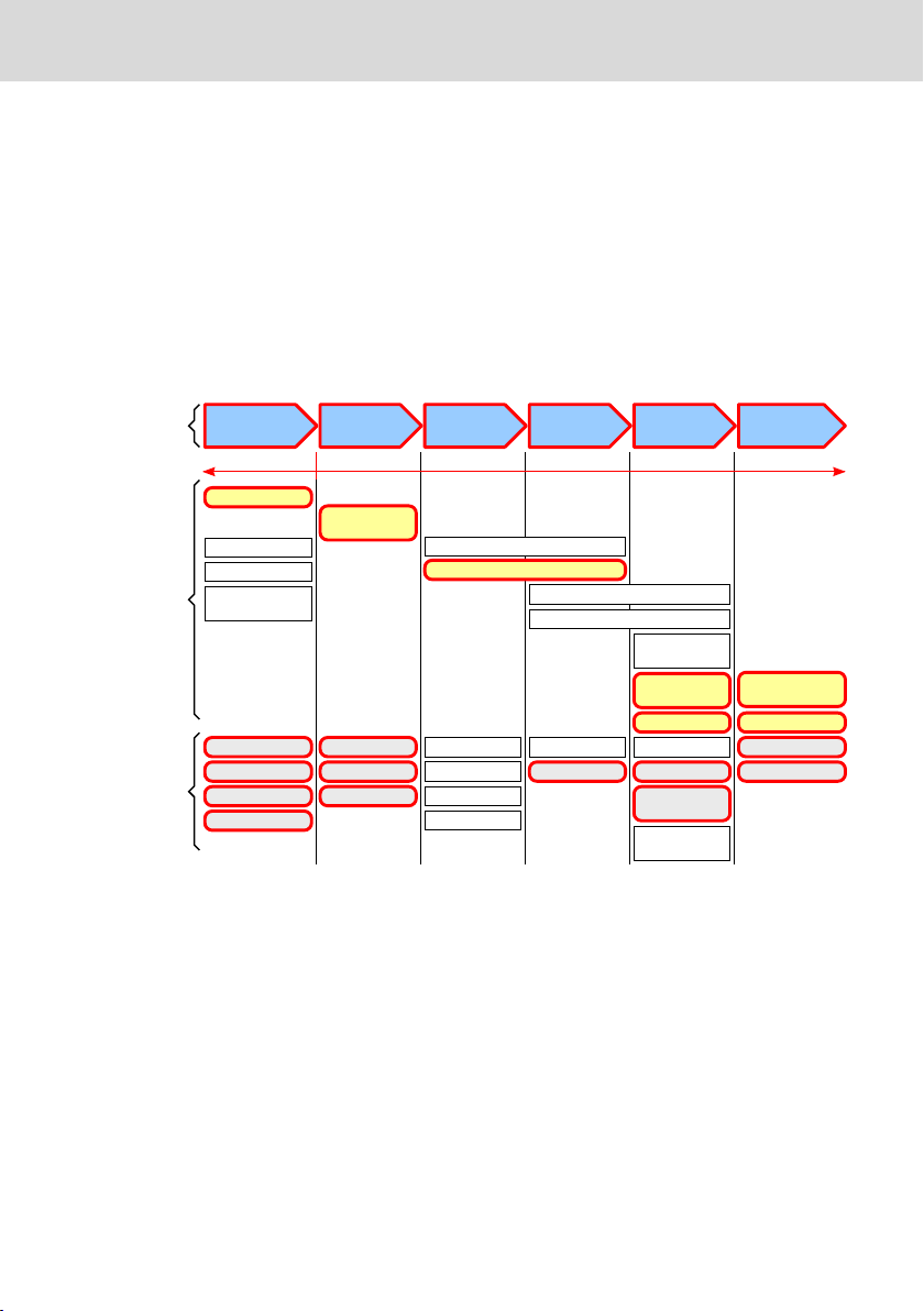
1.1 Overview on target groups and product phases
In the following illustration, the framed activities, product phases and target
groups refer to the present documentation.
Example:
In the product phase "Mounting (assembly/installation)", the "mechanic/electri-
cian" can execute the activity "install" using this documentation.
Presales Aftersales
Selection Mounting
(assembly/installation)
Engineering
Commissioning
Operation
Decommissioning
Product
phases
Target
groups
Activities
Design engineer
Programmer
Technologist
Process
specialist
Select
Prepare
Design
Construct
Mechanic/
electrician
Unpack
Mount
Install
Programmer
Commissioning engineer
Parameterize
Program
Configure
Simulate
Technologist
Process specialist
Optimize
Test
Machine
operator
Maintenance
technician
Service
Operate
Maintain
Remove
faults
Create
the NC program
Mechanic/
electrician
Disposal company
Dismount
Dispose
Fig. 1-1: Assigning the present documentation to the target groups, product phases and ac-
tivities of the target group
1.2 Purpose
This document instructs the technical staff of the machine manufacturer on how
to perform the mechanical and electrical installation safely and on how to com-
mission the device.
Required qualifications: Individual who is able to assess the tasks assigned and
identify possible safety risks owing to qualification in the subject, knowledge
and experience. The individual should also be familiar with the standards and
regulations.
Y-Repeater Bosch Rexroth AG
About this documentation
DOK-SUPPL*-VAC*01*****-IT03-EN-P 1/33

1.3 Scope
This document is valid for
●Y-repeater (type designation code VAC01.1S-YD1-NNNN)
●Y-repeater with additional digital input to enable the "Energy Save Mode" at
the passive operator display (type designation code VAC01.1S-YD1-TCES)
The type code specifications are located on the type plate of the device (also re-
fer to chapter 2.1 "Product identification" on page 3 and chapter 15 "Order-
ing information" on page 27).
1.4 Related documents
Title Part number and document type
Rexroth IndraControl
VAP 01
Power Supply Unit
R911339613
Operating Instructions
Rexroth IndraControl
VPB 40.3
Control cabinet PC
R911336750
Operating Instructions
Rexroth IndraControl
VDP 16.3/40.3/60.3
Operator Display
R911336378
Operating Instructions
Rexroth IndraControl
VDP 15.3, 18.3, 21.3 Multi Touch
Operator Display – Built-In Devices
R911341191
Operating Instructions
Tab. 1-1: Y-repeater, further documents
1.5 Terms and abbreviations
Name Explanation
ESM Digital input to enable the "Energy Save Mode" at the passive operator display
CDI Compact Display Interface. Interface to connect the remote operator display to
the control cabinet PC
XGA Extended Graphics Array. Designates a graphics card type for the IBM PS/2 series
PC launched by IBM in 1990. In contrast to the preceding standard VGA, XGA did
not become an industrial standard in the PC area
Bosch Rexroth AG
About this documentation
Y-Repeater
2/33 DOK-SUPPL*-VAC*01*****-IT03-EN-P

Name Explanation
SVGA Super Video Graphics Array. Names:
1. In general graphics cards whose performance exceed the VGA standard
2. Specific computer standard (VESA 1.2), which is downward compatible to
VGA, which defines specific combinations of screen resolution and number
of colors (color depth) as well as the refresh rate. At least the following res-
olutions can be displayed on a combination of a graphics card and screen,
both supporting VESA 1.2:
●800 × 600 pixels
●1024 × 768 pixels
●1280 × 1024 pixels
3. The resolution 800 × 600 pixels (aspect ratio 4:3) independent of other
parameters
SXGA Super Extended Graphics Array. Designates a resolution of 1280 × 1024 pixels,
resulting in an aspect ratio of 5:4
USB Universal Serial Bus. Serial bus system to connect a computer to external devices
Boot Booting the control cabinet PC
Tab. 1-2: Terms and abbreviations
1.6 Customer feedback
Customer requests, comments or suggestions for improvement are of great im-
portance to us. Please email your feedback on the documentations to Feed-
back.Documentation@boschrexroth.de. Directly insert comments in the elec-
tronic PDF document and send the PDF file to Bosch Rexroth.
2 Product identification and scope of delivery
2.1 Product identification
The type plate is located on the rear panel.
Y-Repeater Bosch Rexroth AG
Product identification and scope of delivery
DOK-SUPPL*-VAC*01*****-IT03-EN-P 3/33

Bosch Re xroth AG D-64711 Erbach
Ma de in Germa ny
MA6/210-7402-M
U
N
IN 3AC 230V 50/60 Hz
I
N
OUT 10/7,5/5/5/1,5/1,5 A max.
I-C-B-T-V
SW-Vers ion V0,002
MNR: 1070086300 -105 04W03
1070
SN: 123456789
13026
2
3
6
7
7
10
11
12
13
14
9
8
5
4
1
Bosch rexroth Electric Drives and Controls GmbH
D-64711 Erbach Made in Germany
BTV40.1AHB-256S-P5C-
UN-FW
UNIN 3AC 230V 50760Hz
IN
OUT 10/7,5/5/5/1,5/1,5A max.
I-C-B-T-V
SW-Version V0,002
MNR: 1070170021 -101 03W19
7261
IND.CONT.EQ 17YB
SN: 123456814
15
16
Made in Germany
UN: AC 230V / 115V
IN: 0,7A / 1,4A
MNR: 1070086255 -101 V-Nr: 1
TYP: PCPNL PEN400J1287 IS110-T
Bosch Rexroth Electric Drives and Controls GmbH
D-6471 1 Erbach
SN: 004012652
7261
IND.CONT-EQ 17YB
XXXXXXXXXXXXXXXXX
I-C-B-H-T-V
FD: 05W01
12
3
4
8
9
5
10
6
12
11
13
14
15
16
1Logotype
2Division or plant number
3Type code (type designation code)
4Parts number
5State of revision
6Date of manufacture (yyWww)
7Nominal voltage
8Nominal current
9Test marking
10 Version number
11 CE marking
12 Underwriters Laboratories Inc. mark
13 Serial number as barcode
14 Serial number
15 Designation of origin
16 Company address
Fig. 2-1: Type plates, example
2.2 Scope of delivery
●Y-repeater
●Safety instructions
●Plugs for X1S1 or X1S2
3 Use of the safety instructions
3.1 Structure of the safety instructions
The safety instructions are structured as follows:
Burns and chemical burns due to wrong
battery treatment!
CAUTION
Safety alert symbol
Signal word
Consequences and
source of danger
Avoiding danger
Do not open the batteries and do not heat them over 80 °C.
Fig. 3-1: Structure of the safety instructions
Bosch Rexroth AG
Use of the safety instructions
Y-Repeater
4/33 DOK-SUPPL*-VAC*01*****-IT03-EN-P

3.2 Explaining signal words and safety alert symbol
The safety instructions in this documentation contain specific signal words (dan-
ger, warning, caution, notice) and, if necessary, a safety alert symbol (according
to ANSI Z535.6-2006).
The signal word is used to draw attention to the safety instruction and also pro-
vides information on the severity of the hazard.
The safety alert symbol (a triangle with an exclamation point), which precedes
the signal words danger,warning and caution is used to alert the reader to per-
sonal injury hazards.
DANGER
In case of non-compliance with this safety instruction, death or serious injury
will occur.
WARNING
In case of non-compliance with this safety instruction, death or serious injury
can occur.
CAUTION
In case of non-compliance with this safety instruction, minor or moderate injury
can occur.
NOTICE
In case of non-compliance with this safety instruction, material damage can oc-
cur.
3.3 Symbols used
Hints are represented as follows:
This is an information.
Tips are represented as follows:
This is a tip.
Y-Repeater Bosch Rexroth AG
Use of the safety instructions
DOK-SUPPL*-VAC*01*****-IT03-EN-P 5/33

3.4 Signal graphic explanation on the device
krax
Prior to the installation and commissioning of the device, refer to the
device documentation.
4 Intended use
The Y-repeater is required to connect two operator displays to a control cabinet
PC.
Risk of damaging of the device if not expressly
stated accessories, mounting parts and other
components, cables, and lines are used.
NOTICE
The Y-repeater may be used only as intended and with the accessories, mount-
ing parts and other components specified in this documentation. Components
that are not expressly mentioned must neither be attached nor connected. The
same applies to cables and lines.
Operation must only be carried out with the hardware component configura-
tions and combinations that are expressly specified.
The Y-repeater can be used for the following IndraControl V device:
●Control cabinet PC Rexroth IndraControl VSB 40.3
The Y-repeater may only be operated under the mounting and installation condi-
tions, the position, and the ambient conditions (temperature, degree of protec-
tion, humidity, EMC etc.) specified in the related documentation.
5 Accessories
5.1 External 24 V power supply unit
Ordering code Part number Description
VAP01.1H-W23-024-010-NN R911171065 External 24 V power supply unit for UPS
and IndraControl V-devices
Tab. 5-1: Ordering data, 24 V power supply unit for UPS and IndraControl V-devices
Bosch Rexroth AG
Accessories
Y-Repeater
6/33 DOK-SUPPL*-VAC*01*****-IT03-EN-P

5.2 Uninterruptible power supply
Ordering code Part number Description
VAU 01.1U R911171024 UPS with USB communication interface
and integrated accumulator
Output voltage 24 V DC, 240 W
Tab. 5-2: Ordering data, uninterruptible power supply
5.3 Connecting cables for the CDI interface
Ordering code Part number Description
RKB0008/000,5 (*******-*******-*******) R911171484 Length: 0.5 m
RKB0008/001,0 (*******-*******-*******) R911171485 Length: 1 m
RKB0008/002,5 (*******-*******-*******) R911170151 Length: 2.5 m
RKB0008/005,0 (*******-*******-*******) R911170152 Length: 5 m
RKB0008/007,5 (*******-*******-*******) R911172971 Length: 7.5 m
RKB0008/010,0 (*******-*******-*******) R911170153 Length: 10 m
RKB0008/015,0 (*******-*******-*******) R911171183 Length: 15 m
RKB0008/020,0 (*******-*******-*******) R911171184 Length: 20 m
RKB0008/025,0 (*******-*******-*******) R911170154 Length: 25 m
RKB0008/030,0 (*******-*******-*******) R911171381 Length: 30 m
RKB0008/035,0 (*******-*******-*******) R911171369 Length: 35 m
RKB0008/040,0 (*******-*******-*******) R911171382 Length: 40 m
RKB0008/050,0 (*******-*******-*******) R911171383 Length: 50 m
RKB0008/055,0 (*******-*******-*******) R911173779 Length: 55 m
RKB0008/060,0 (*******-*******-*******) R911173780 Length: 60 m
RKB0008/065,0 (*******-*******-*******) R911173781 Length: 65 m
RKB0008/070,0 (*******-*******-*******) R911173782 Length: 70 m
Tab. 5-3: CDI connecting cable
Two cables are always required to establish a connection between
the VxB and the VDP.
6 Ambient conditions
In operation Transport Storage
Ambient temperature +5 °C to +45 °C -20 °C to +60 °C -20 °C to +60 °C
Maximum temperature
gradient
Temporal temperature
changes up to 3 °C per
minute
Temporal temperature
changes up to 3 °C per
minute
Temporal temperature
changes up to 3 °C per
minute
Y-Repeater Bosch Rexroth AG
Ambient conditions
DOK-SUPPL*-VAC*01*****-IT03-EN-P 7/33

In operation Transport Storage
Relative humidity Climatic class 3K3 acc.
to EN 60721, condens-
ing not allowed.
Max. 80 % air humidity
at 25 °C
Climatic class 3K3 acc.
to EN 60721, condens-
ing not allowed.
Max. 80 % air humidity
at 25 °C
Climatic class 3K3 acc.
to EN 60721, condens-
ing not allowed.
Max. 80 % air humidity
at 25 °C
Air pressure Up to 3,000 m above
sea level acc. to EN
61131-2
Up to 3,000 m above
sea level acc. to EN
61131-2
Up to 3,000 m above
sea level acc. to EN
61131-2
Mechanical strength Maximum vibration
Frequency range:
10 Hz to 150 Hz
Excursion:
0.75 mm at 10 Hz to
57 Hz
Acceleration:
1 g at 57 Hz to 150 Hz
Test duration per axis:
10 frequency cycles
Frequency throughput
speed:
1 octave/min
Acc. to EN 60068-2-6,
test Fc
Max. shock:
15 g acc. to EN 60
068-2-27, no disturb-
ance of the function
Max. shock:
15 g acc. to EN 60
068-2-27, no disturb-
ance of the function
Contamination level 2 2 2
Tab. 6-1: Ambient conditions
Defective product due to gases jeopardizing
functions
NOTICE
Due to the risk of corrosion, avoid sulphurous gases (e.g. sulphur dioxide (SO2)
and hydrogen suphide (H2S)). The product is not resistant against these gases.
Bosch Rexroth AG
Ambient conditions
Y-Repeater
8/33 DOK-SUPPL*-VAC*01*****-IT03-EN-P

Failure of the product due to contaminated air
NOTICE
●The ambient air must not contain acids, alkaline solutions, corrosive agents,
salts, metal vapors and other electrically conductive contaminants in high
concentrations
●The ambient air must be free of dust
●Housing and installation compartments must at least comply with degree of
protection IP 54 according to DIN EN 60529
7 Standards
7.1 Standards used
Standard Meaning
EN 60 61000-6-4 Generic standards - Emission standard (industrial environments)
EN 60 61000-6-2 Generic standards – Noise immunity (industrial environments)
EN 61558-2-6 Transformer for 24 V power supply unit, safe separation
EN 60664-1 Overvoltage category II
EN 60 529 Degrees of protection (including housings and installation compart-
ments)
EN 60 068-2-6 Vibration test
EN 60068-2-27 Shock test
EN 60721-3-3 Classification of ambient conditions, operation
EN 60721-3-2 Classification of ambient conditions, transport
EN 60721-3-1 Classification of ambient conditions, storage
UL 508 Industrial Control Equipment
Tab. 7-1: Used standards, Y-repeater
7.2 CE marking
7.2.1 Declaration of conformity
The electronic products described in the present operating instructions comply
with the requirements and the target of the following EU directive and with the
following harmonized European standards:
EMC directive 2004/108/EC
The electronic products described in the present operating instructions are in-
tended for use in industrial environments and comply with the following require-
ments:
Y-Repeater Bosch Rexroth AG
Standards
DOK-SUPPL*-VAC*01*****-IT03-EN-P 9/33
Standard Title Edition
DIN EN 61000-6-4
(VDE 0839-6-4)
Electromagnetic compatibility (EMC)
Part 6-4: Generic standards – Emission standard for indus-
trial environments (IEC 61000-6-4:2006)
September
2007
DIN EN 61000-6-2
(VDE 0839-6-2)
Electromagnetic compatibility (EMC)
Part 6-2: Generic standards – Noise immunity for industrial
environments (IEC 61000-6-2:2005)
March 2006
Tab. 7-2: Standards for electromagnetic compatibility (EMC)
Loss of CE conformity due to modifications at the device.
CE marking applies only to the device upon delivery. After modifying
the device, verify CE conformity.
7.3 UL/CSA certified
The devices are certified acc. to
●UL508 (Industrial Control Equipment)
●C22.2 no. 142-M1987 (CSA)
UL file no. E210730
However, there can be combinations or extension stages with a limited or miss-
ing certification. Thus, verify the registration according to the UL marking on the
device.
Loss of UL/CSA conformity due to modifications at the device.
UL and CSA marking applies only to the device upon delivery. After
modifying the device, verify UL and CSA conformity.
8 Technical data
8.1 Degree of protection and weight
Degree of protection IP 20
Weight 0.54 kg
Tab. 8-1: Degree of protection and weight
Bosch Rexroth AG
Technical data
Y-Repeater
10/33 DOK-SUPPL*-VAC*01*****-IT03-EN-P

8.2 Input voltages
8.2.1 24 V input
Nominal input voltage 24 V DC (use a 24 V power supply unit acc. to DIN
EN 60742, classification VDE 0551, for example
the power supply unit VAP01.1H-W23-024-010-
NN, part number R911171065)
Input voltage range 24 V DC +20 %, -15 %
Emitted interference and surge immunity Umax = 35 V (for t < 100 ms)
Current consumption at UNMax. 0.165 A at 24 V
Input fuse None
Switch-on threshold 22 V ±5 %
Switch-off threshold 19 V ±5 %
Max. power consumption 4 W
Reverse voltage protection Yes
Tab. 8-2: Characteristic values of the 24 V input
8.2.2 Digital 24 V inputs SEL and ESM
Reverse voltage protection Yes
Input voltage:
Nominal value at "0"
Nominal value at "1"
-3 V to 15 V
18 V to 30 V
Input current:
Nominal value at "0"
Nominal value at "1"
< 2.5 mA
2.8 mA to 6 mA
Cable length (unshielded) < 100 m
Short-circuit protection, overcurrent protection Typ. 0.6 A
Tab. 8-3: Characteristic values of the digital 24 V inputs SEL and ESM
This ESM input is only available for the Y-repeater VAC01.1S-YD1-
TCES.
Y-Repeater Bosch Rexroth AG
Technical data
DOK-SUPPL*-VAC*01*****-IT03-EN-P 11/33

9 Interfaces
9.1 Connector panel
2
3
4
1
5
6
7
8
7
8
9
VAC01.1S-YD1-NNNN VAC01.1S-YD1-TCES
①24 V input "Energy Save Mode" for the
passive operator display, X1S2
②24 V switching input, X1S1/X1S2
③24 V voltage connection, X1S1/X1S2
④LED to display the supply voltage, Vin
⑤LED for status display (active/passive)
of the connected operator display
⑥CDI interface to the control cabinet PC,
XSER, XVID
⑦CDI interface to the first operator dis-
play, XSER1, XVID1
⑧CDI interface to the second operator
display, XSER2, XVID2
⑨Functional earth
Fig. 9-1: Connector panel of the Y-repeater
Bosch Rexroth AG
Interfaces
Y-Repeater
12/33 DOK-SUPPL*-VAC*01*****-IT03-EN-P
Labeling at the
housing
Connection type Connector type (integra-
ted)
Mating connector or cable
(from outside)
X1S1 24 V voltage supply
1 digital 24 V input
Phönix connector strip,
4-pin, MC1,5/4- G-3,5THT
Phönix socket strip,
4-pin, FK-MCP 1,5/4-
ST-3,5
X1S21) 24 V voltage supply
2 digital 24 V inputs
Phönix connector strip,
5-pin, MC1,5/5-
G-3,5THT1
Phönix socket strip,
5-pin, FK-MCP 1,5/5-
ST-3,5
XSER
XVID
CDI interface to the control
cabinet PC
Two RJ45 sockets Two RJ45 plugs
XSER1
XVID1
CDI interface to the first op-
erator display
Two RJ45 sockets Two RJ45 plugs
XSER2
XVID2
CDI interface to the second
operator display
Two RJ45 sockets Two RJ45 plugs
Functional earth (FE) M5 Ring cable lug
1) Only VAC01.1S-YD1-TCES
Tab. 9-1: Interfaces and connections at the Y-repeater
9.2 24 V voltage supply and digital 24 V inputs
9.2.1 VAC 01.1S-YD1-NNNN – Connection terminal X1S1
Pin Labeling Function
1 24 + 24 V supply voltage
2 24 – 0 V supply voltage
3 SEL – 0 V switching input
4 SEL + 24 V switching input
Tab. 9-2: Pin assignment X1S1
Switching input SEL Active operator display
0 (no 24 V available) Operator display 1 is active (XVID1, XSER1)
1 (24 V available) Operator display 2 is active (XVID2, XSER2)
Tab. 9-3: Selecting the active operator display
Y-Repeater Bosch Rexroth AG
Interfaces
DOK-SUPPL*-VAC*01*****-IT03-EN-P 13/33
9.2.2 VAC 01.1S-YD1-TCES – Connection terminal X1S2
Pin Labeling Function
1 24 + 24 V supply voltage
2 24 – 0 V supply voltage
3 ESM/SEL – 0 V for switching and ESM
4 SEL + 24 V switching input
5 ESM + Enables the "Energy Save Mode" at
the passive operator display
Tab. 9-4: Pin assignment X1S2
Switching input SEL Active operator display
0 (no 24 V available) Operator display 1 is active (XVID1, XSER1)
1 (24 V available) Operator display 2 is active (XVID2, XSER2)
Tab. 9-5: Selecting the active operator display
Input ESM Passive operator display
0 (no 24 V available) "Energy Save Mode" at the passive operator display is not enabled
1 (24 V available) "Energy Save Mode" at the passive operator display is enabled
Tab. 9-6: Enables the "Energy Save Mode" at the passive operator display
No operation possible at the operator display at which the power
LED flashes (operator display is passive).
The power LED is permanently on at the active operator display.
9.3 CDI interface
The Y-repeater is connected to the control cabinet PC and to two operator dis-
plays via the CDI interfaces (XSER, XVID, XSER1, XVID1, XSER2, XVID2).
Connection Function
XSER, XVID CDI interface to the control cabinet PC
XSER1, XVID1 CDI interface to operator display no. 1
XSER2, XVID2 CDI interface to operator display no. 2
Tab. 9-7: Assigning the three CDI interfaces
Bosch Rexroth AG
Interfaces
Y-Repeater
14/33 DOK-SUPPL*-VAC*01*****-IT03-EN-P
This manual suits for next models
1
Table of contents


