Bosch GOS 10 User manual

Robert Bosch GmbH
Power Tools Division
70745 Leinfelden-Echterdingen
Germany
www.bosch-pt.com
1 609 92A 00D (2012.12) T / 118 UNI
GOS 10,8 V-LI Professional
de Originalbetriebsanleitung
en Original instructions
fr Notice originale
es Manual original
pt Manual original
it Istruzioni originali
nl Oorspronkelijke
gebruiksaanwijzing
da Original brugsanvisning
sv Bruksanvisning i original
no Original driftsinstruks
fi Alkuperäiset ohjeet
el Πρωτότυπο οδηγιών χρήσης
tr Orijinal işletme talimatı
pl Instrukcja oryginalna
cs Původní návod k používání
sk Pôvodný návod na použitie
hu Eredeti használati utasítás
ru Оригинальное руководство по
эксплуатации
uk Оригінальна інструкція з
експлуатації
ro Instrucţiuni originale
bg Оригинална инструкция
sr Originalno uputstvo za rad
sl Izvirna navodila
hr Originalne upute za rad
et Algupärane kasutusjuhend
lv Instrukcijas oriģinālvalodā
lt Originali instrukcija
ar
fa
ςТЎϩХʉ ЌТϾϦφЍʉ ʌμВТЎϺυ
ΖЎϩʉ ˒μВЖЙʉʓ ИͳϞφЁʑ
OBJ_BUCH-1311-003.book Page 1 Tuesday, December 11, 2012 9:38 AM

2|
1 609 92A 00D | (11.12.12) Bosch Power Tools
Deutsch. . . . . . . . . . . . . . . . . . . . . . . . . . . . . . . . . . . . . . . . . Seite 6
English . . . . . . . . . . . . . . . . . . . . . . . . . . . . . . . . . . . . . . . . . .Page 10
Français . . . . . . . . . . . . . . . . . . . . . . . . . . . . . . . . . . . . . . . . .Page 15
Español. . . . . . . . . . . . . . . . . . . . . . . . . . . . . . . . . . . . . . . . Página 19
Português . . . . . . . . . . . . . . . . . . . . . . . . . . . . . . . . . . . . . . Página 23
Italiano . . . . . . . . . . . . . . . . . . . . . . . . . . . . . . . . . . . . . . . . Pagina 27
Nederlands . . . . . . . . . . . . . . . . . . . . . . . . . . . . . . . . . . . . . Pagina 31
Dansk . . . . . . . . . . . . . . . . . . . . . . . . . . . . . . . . . . . . . . . . . . . Side 35
Svenska . . . . . . . . . . . . . . . . . . . . . . . . . . . . . . . . . . . . . . . . . Sida 38
Norsk. . . . . . . . . . . . . . . . . . . . . . . . . . . . . . . . . . . . . . . . . . . . Side 41
Suomi . . . . . . . . . . . . . . . . . . . . . . . . . . . . . . . . . . . . . . . . . . . Sivu 45
Ελληνικά . . . . . . . . . . . . . . . . . . . . . . . . . . . . . . . . . . . . . . . Σελίδα 48
Türkçe. . . . . . . . . . . . . . . . . . . . . . . . . . . . . . . . . . . . . . . . . . Sayfa 52
Polski . . . . . . . . . . . . . . . . . . . . . . . . . . . . . . . . . . . . . . . . . Strona 56
Česky . . . . . . . . . . . . . . . . . . . . . . . . . . . . . . . . . . . . . . . . . Strana 60
Slovensky . . . . . . . . . . . . . . . . . . . . . . . . . . . . . . . . . . . . . . Strana 64
Magyar . . . . . . . . . . . . . . . . . . . . . . . . . . . . . . . . . . . . . . . . . Oldal 67
Русский . . . . . . . . . . . . . . . . . . . . . . . . . . . . . . . . . . . . Страница 71
Українська . . . . . . . . . . . . . . . . . . . . . . . . . . . . . . . . . . . Сторінка 76
Română. . . . . . . . . . . . . . . . . . . . . . . . . . . . . . . . . . . . . . . . Pagina 80
Български . . . . . . . . . . . . . . . . . . . . . . . . . . . . . . . . . . Страница 84
Srpski . . . . . . . . . . . . . . . . . . . . . . . . . . . . . . . . . . . . . . . . . Strana 88
Slovensko . . . . . . . . . . . . . . . . . . . . . . . . . . . . . . . . . . . . . . . Stran 91
Hrvatski. . . . . . . . . . . . . . . . . . . . . . . . . . . . . . . . . . . . . . .Stranica 95
Eesti . . . . . . . . . . . . . . . . . . . . . . . . . . . . . . . . . . . . . . . . Lehekülg 98
Latviešu . . . . . . . . . . . . . . . . . . . . . . . . . . . . . . . . . . . . . .Lappuse 102
Lietuviškai. . . . . . . . . . . . . . . . . . . . . . . . . . . . . . . . . . . . .Puslapis 105
. . . . . . . . . . . . . . . . . . . . . . . . . . . . . . 110
. . . . . . . . . . . . . . . . . . . . . . . . . . . . . . 114
OBJ_BUCH-1311-003.book Page 2 Tuesday, December 11, 2012 9:33 AM

3|
1 609 92A 00D | (11.12.12) Bosch Power Tools
10,8 V
AL 1130 CV (10,8 V)
2 607 225 134 (EU)
2 607 225 136 (UK)
2 607 225 138 (AUS)
AL 1115 CV (3,6
–
10,8 V)
2 607 225 514 (EU)
2 607 225 516 (UK)
2 610 014 567 (Ø 17 mm, 1,22 m)
2 610 014 568 (Ø 9,5 mm, 0,91 m)
2 610 014 564 (Ø 17 mm)
2 610 014 565 (Ø 9,5 mm)
2 610 014 570 (0,91 m)
612
Ø
Ø
OBJ_BUCH-1311-003.book Page 3 Tuesday, December 11, 2012 9:33 AM

1 60992A 00D | (11.12.12)Bosch Power Tools
4|
1
6
7
9
12
8
4
3
2
5
10
11
GOS 10,8 V-LI
OBJ_BUCH-1311-003.book Page 4 Tuesday, December 11, 2012 9:33 AM

5|
1 60992A 00D | (11.12.12)Bosch Power Tools
1
14
15
16
17
19
18
7
13
6
C
BA
OBJ_BUCH-1311-003.book Page 5 Tuesday, December 11, 2012 9:33 AM

6| Deutsch
1 60992A 00D | (11.12.12)Bosch Power Tools
Deutsch
Sicherheitshinweise
Digitale Inspektionskamera
Lesen Sie alle Sicherheitshinweise und An-
weisungen. Versäumnisse bei der Einhaltung
der Sicherheitshinweise und Anweisungen
können elektrischen Schlag, Brand und/oder
schwere Verletzungen verursachen.
Lassen Sie die Inspektionskamera von qualifiziertem
Fachpersonal und nur mit Original-Ersatzteilen repa-
rieren. Damit wird sichergestellt, dass die Sicherheit der
Inspektionskamera erhalten bleibt.
Arbeiten Sie mit der Inspektionskamera nicht in explo-
sionsgefährdeter Umgebung, in der sich brennbare
Flüssigkeiten, Gase oder Stäube befinden. In der Ins-
pektionskamera können Funken erzeugt werden, die den
Staub oder die Dämpfe entzünden.
Nehmen Sie den Akku vor allen Arbeiten an der Inspek-
tionskamera (z.B. Montage, Wartung etc.) sowie bei
deren Transport und Aufbewahrung aus der Inspek-
tionskamera.
Öffnen Sie den Akku nicht. Es besteht die Gefahr eines
Kurzschlusses.
Schützen Sie den Akku vor Hitze, z.B. auch vor
dauernder Sonneneinstrahlung, Feuer, Wasser
und Feuchtigkeit. Es besteht Explosionsgefahr.
Halten Sie den nicht benutzten Akku fern von Büro-
klammern, Münzen, Schlüsseln, Nägeln, Schrauben
oder anderen kleinen Metallgegenständen, die eine
Überbrückung der Kontakte verursachen könnten. Ein
Kurzschluss zwischen den Akkukontakten kann Verbren-
nungen oder Feuer zur Folge haben.
Bei falscher Anwendung kann Flüssigkeit aus dem
Akku austreten. Vermeiden Sie den Kontakt damit. Bei
zufälligem Kontakt mit Wasser abspülen. Wenn die
Flüssigkeitindie Augen kommt, nehmen Sie zusätzlich
ärztliche Hilfe in Anspruch. Austretende Akkuflüssigkeit
kann zu Hautreizungen oder Verbrennungen führen.
Bei Beschädigung und unsachgemäßem Gebrauch des
AkkuskönnenDämpfe austreten.FührenSieFrischluft
zu und suchen Sie bei Beschwerden einen Arzt auf. Die
Dämpfe können die Atemwege reizen.
Laden Sie die Akkus nur mit Ladegeräten auf, die vom
Hersteller empfohlen werden. Durch ein Ladegerät, das
für eine bestimmte Art von Akkus geeignet ist, besteht
Brandgefahr, wenn es mit anderen Akkus verwendet wird.
Verwenden Sie den Akku nur in Verbindung mit Ihrer
Bosch-Inspektionskamera. Nur so wird der Akku vor ge-
fährlicher Überlastung geschützt.
Verwenden Sie nur original Bosch-Akkus mit der auf
dem Typenschild Ihrer Inspektionskamera angegebe-
nen Spannung. Bei Gebrauch anderer Akkus, z.B. Nach-
ahmungen, aufgearbeiteter Akkus oder Fremdfabrikaten,
besteht die Gefahr von Verletzungen sowie Sachschäden
durch explodierende Akkus.
Drücken Sie nach dem automatischen Abschalten der
Inspektionskamera nicht weiter auf den Ein-/Ausschal-
ter. Der Akku kann beschädigt werden.
Richten Sie den Lichtstrahl nicht auf Personen oder
Tiere und blicken Sie nicht selbst in den Lichtstrahl,
auch nicht aus größerer Entfernung.
Überprüfen Sie vor dem Einsatz der Inspektionskamera
den Arbeitsbereich. Kein Teil der Inspektionskamera
darf in Kontakt mit elektrischen Leitungen, sich bewe-
genden Teilen oder chemischen Substanzen kommen.
Unterbrechen Sie den Stromkreis von elektrischen Lei-
tungen, die im Arbeitsbereich verlaufen. Diese Maßnah-
men vermindern das Risiko von Explosionen, elektrischem
Schlag und Sachschäden.
Tragen Sie angemessene persönliche Schutzausrüs-
tung wie Schutzbrille, Schutzhandschuhe oder Atem-
schutzmaske,wennsichgesundheitsgefährdende Sub-
stanzen im Arbeitsbereich befinden. Abwasserkanäle
oder ähnliche Bereiche können feste, flüssige oder gasför-
mige Substanzen enthalten, die giftig, infektiös, ätzend
oder auf andere Art gesundheitsgefährdend sind.
Achten Sie besonders auf Sauberkeit, wenn Sie in
Bereichen mit gesundheitsgefährdenden Substanzen
arbeiten. Essen Sie während der Arbeit nicht. Vermei-
den Sie den Kontakt mit den gesundheitsgefährdenden
Substanzen und reinigen Sie nach der Arbeit Hände und
andere Körperteile, die in Kontakt gekommen sein könn-
ten, mit heißer Seifenlauge. Dadurch wird die Gesund-
heitsgefährdung verringert.
Stehen Sie nicht im Wasser, wenn Sie die Inspektions-
kamerabenutzen.Durch Arbeiten imWasser besteht das
Risiko eines elektrischen Schlages.
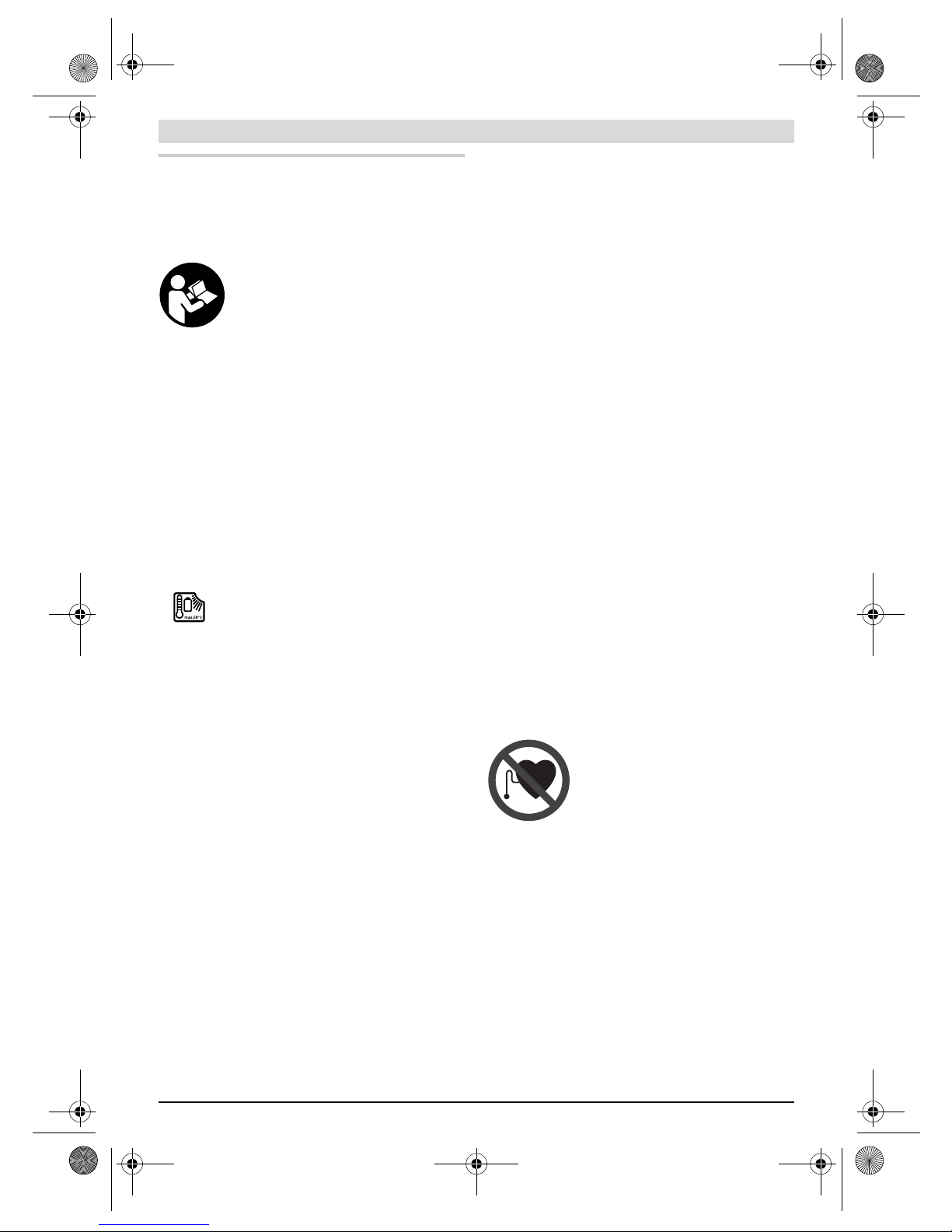
Magnet
Bringen Sie den Magnet 15 nicht in die
NähevonHerzschrittmachern.Durchden
Magnet wird ein Feld erzeugt, das die Funk-
tion von Herzschrittmachern beeinträchti-
gen kann.
Halten Sie den Magnet 15 fern von magnetischen Da-
tenträgern und magnetisch empfindlichen Geräten.
Durch die Wirkung des Magnets kann es zu irreversiblen
Datenverlusten kommen.
Produkt- und Leistungsbeschreibung
Bitte klappen Sie die Aufklappseite mit der Darstellung der In-
spektionskameraauf, und lassen Sie diese Seite aufgeklappt,
während Sie die Betriebsanleitung lesen.
Bestimmungsgemäßer Gebrauch
Die digitale Inspektionskamera ist geeignet zur Inspektion
schwer zugänglicher oder dunkler Bereiche. Sie ist nach Mon-
tage der mitgelieferten Hilfsmittel amKamerakopf auch zum
Bewegen und Entfernen kleiner und leichter Gegenstände
(z.B. kleiner Schrauben) geeignet.
OBJ_BUCH-1311-003.book Page 6 Tuesday, December 11, 2012 9:33 AM

Deutsch | 7
Bosch Power Tools 1 60992A 00D | (11.12.12)
Die digitale Inspektionskamera darf nicht für medizinische
Zwecke verwendet werden. Sie ist ebenso nicht zumBehe-
ben von Rohrverstopfungen oder demEinziehen von Kabeln
bestimmt.
Abgebildete Komponenten
Die Nummerierung der abgebildeten Komponenten bezieht
sichaufdieDarstellung der Inspektionskamera auf der Grafik-
seite.
1Handgerät
2Taste Beleuchtung verstärken „+“
3Ein-Aus-Taste
4Taste Beleuchtung verringern „–“
5Display
6Kamerakabel
7Kamerakopf
8Kameralinse
9Leuchte imKamerakopf
10 Akku*
11 Akku-Entriegelungstaste
12 Verlängerung Kamerakabel*
13 Hülse amKameraanschluss
14 Kameraanschluss
15 Magnet
16 Haken
17 Spiegel
18 Buchse Videoausgang
19 Videokabel
*Abgebildetes oder beschriebenes Zubehör gehört nicht zum
Standard-Lieferumfang. Das vollständige Zubehör finden Sie in
unserem Zubehörprogramm.
Technische Daten
Montage
Nehmen Sie den Akku vor allen Arbeiten an der Inspek-
tionskamera(z.B. Montage, Wartung etc.)sowiebeide-
ren Transport und Aufbewahrung aus der Inspektions-
kamera.
Akku laden
Benutzen Sie nur die auf der Grafikseite aufgeführten
Ladegeräte. Nur diese Ladegeräte sind auf den bei Ihrer In-
spektionskamera verwendeten Li-Ionen-Akku abgestimmt.
Hinweis:Der Akku wird teilgeladen ausgeliefert. Umdie volle
Leistung des Akkus zu gewährleisten, laden Sie vor demers-
ten Einsatz den Akku vollständig imLadegerät auf.
Der Li-Ionen-Akku kann jederzeit aufgeladen werden, ohne
dieLebensdauer zu verkürzen. Eine Unterbrechung des Lade-
vorganges schädigt den Akku nicht.
Der Akku ist mit einer NTC-Temperaturüberwachung ausge-
stattet, welche ein Aufladen nur imTemperaturbereich zwi-
schen 0 °C und 45 °C zulässt. Dadurch wird eine hohe Akku-
Lebensdauer erreicht.
Akku-Ladezustandsanzeige
Bei eingeschalteter Inspektionskamera erscheint imDisplay
5eine Anzeige des Akku-Ladezustands:
Akku entnehmen
Zur Entnahme des Akkus 10 drücken Sie die Entriegelungs-
tasten 11 und ziehen den Akku nach hinten aus der Inspek-
tionskamera. Wenden Sie dabei keine Gewalt an.
Kamerakabel montieren (siehe Bild A)
Für den Betrieb der Inspektionskamera muss das Kamera-
kabel 6amHandgerät 1montiert werden.
Stecken Sie das Kamerakabel 6so auf den Kameraanschluss
14, dass der Stift des Kamerakabels wie imBild dargestellt in
die Aussparung amKameraanschluss eingreift. Schieben Sie
dieHülse13amKameraanschlussüberdasKamerakabelund
schrauben Sie sie imUhrzeigersinn handfest an.
ZumAbnehmen des Kamerakabels 6schrauben Sie die Hülse
13 gegen den Uhrzeigersinn auf und ziehen das Kamerakabel
ab.
Verlängerung Kamerakabel montieren (Zubehör)
Umeine Kamerakabel-Verlängerung 12 zu montieren, müssen
Sie das vorhandene Kamerakabel 6abnehmen.
Setzen Sie dann die Verlängerung 12 wie bei „Kamerakabel
montieren“ beschrieben auf den Kameraanschluss 14 und
schrauben Sie sie fest.
Bei Bedarf können Sieaufdiegleiche Weise weitere Verlänge-
rungen montieren. Ab etwa 10 mGesamtlänge (inklusive
Kamerakabel) verschlechtert sich jedoch die Bildqualität.
Digitale Inspektionskamera GOS 10,8 V-LI
Sachnummer 3 601 B41 000
Nennspannung V= 10,8
Betriebstemperatur °C –20...+65
Lagertemperatur
(Handgerät ohne Akku) °C –30...+80
Relative Luftfeuchte %5–951)
kleinster Biegeradius
Kamerakabel mm 120
Durchmesser Kamerakopf mm 17/9,5
Schärfentiefebereich Kameralinse mm 38 –
Displaydiagonale mm 68,6
Auflösung Display 320x240
Format Videoausgang NTSC
Betriebsdauer ca. h/Ah 11,5
Gewicht entsprechend
EPTA-Procedure 01/2003 kg 0,68
Maße (Länge x Breite x Höhe) mm 166 x66 x45
1) frei von Betauung
Anzeige Kapazität
>1/2
<1/2
Reserve
OBJ_BUCH-1311-003.book Page 7 Tuesday, December 11, 2012 9:33 AM

8| Deutsch
1 60992A 00D | (11.12.12)Bosch Power Tools
SchraubenSiedasKamerakabel6aufdieletzteVerlängerung
12 wie bei „Kamerakabel montieren“ beschrieben auf.
Prüfen Sie, ob das Kamerakabel und die Verlängerun-
gen fest verbunden sind. Nur bei fester Verbindung sind
Kamerakabel und Verlängerung wasserdicht. Undichte
Verbindungen erhöhen das Risiko eines elektrischen
Schlages oder der Beschädigung der Inspektionskamera.
Spiegel, Magnet oder Haken montieren
(siehe Bild B)
Der Spiegel 17, der Magnet 15 und der Haken 16 können als
Hilfsmittel amKamerakopf 7montiert werden.
Schieben Sie eines der drei Hilfsmittel wie imBild dargestellt
bis zumAnschlag auf die Aussparung amKamerakopf 7.
Hinweis: Der Magnet 15 und der Haken 16 sind nur zumBe-
wegen und Entfernen locker sitzender, kleiner und leichter
Gegenstände geeignet. Bei zu starkemZug kann die Inspek-
tionskamera oder das Hilfsmittel beschädigt werden.
Externe Bildwiedergabe anschließen
(siehe Bild C)
Sie können das Bildsignal der Inspektionskamera auf einen
externen Monitor übertragen, der ein Standard-NTSC-Video-
signal darstellen kann.
Stecken Sie den schwarzen Stecker des mitgelieferten Video-
kabels19indieVideoausgangsbuchse18 anderInspektions-
kamera. Schließen Sie das Videokabel an einen passenden
Monitor an.
Lesen und beachten Sie die Betriebsanleitung des externen
Monitors.
Betrieb
Schützen Sie das Handgerät 1 und den Akku 10 vor
Nässe und direkter Sonneneinstrahlung. Kamerakabel,
Kamerakopf und Verlängerung sind bei richtiger Montage
bis 10 mTiefe wasserdicht. Das Handgerät und der Akku
sindjedoch nicht gegen Wasser geschützt, bei Kontaktmit
Wasser besteht das Risiko eines elektrischen Schlages
oder der Beschädigung.
Setzen Sie die Inspektionskamera keinen extremen
Temperaturen oder Temperaturschwankungen aus.
Lassen Sie sie z.B. nicht längere Zeit imAuto liegen. Las-
sen Sie die Inspektionskamera bei größeren Temperatur-
schwankungen erst austemperieren, bevor Sie sie in Be-
trieb nehmen.
Benutzen Sie die Inspektionskamera nicht, wenn die
Linse am Kamerakopf 7 beschlagen ist. Schalten Sie
die Inspektionskamera erst ein, wenn die Feuchtigkeit
verdunstet ist. Die Inspektionskamera kann sonst be-
schädigt werden.
Inbetriebnahme
Akku einsetzen
Verwenden Sie nur original Bosch Li-Ionen-Akkus mit
der auf dem Typenschild Ihrer Inspektionskamera an-
gegebenen Spannung. Der Gebrauch von anderen Akkus
kann zu Verletzungen und Brandgefahr führen.
Hinweis: Der Gebrauch von nicht für Ihre Inspektionskamera
geeigneten Akkus kann zu Fehlfunktionen oder zur Beschädi-
gung der Inspektionskamera führen.
Setzen Sie den geladenen Akku 10 in den Griff ein, bis dieser
spürbar einrastet und bündig amGriff anliegt.
Ein-/Ausschalten
ZumEinschalten der Inspektionskamera drücken Sie die
Ein-Aus-Taste 3. ImDisplay 5wird das vomKamerakopf 7
aufgenommene Bild angezeigt.
ZumAusschalten der Inspektionskamera drücken Sie die
Ein-Aus-Taste 3erneut.
Wird ca. 20min lang keine Taste an der Inspektionskamera
gedrückt, dann schaltet sie sich zur Schonung des Akkus
automatisch ab.
Leuchte im Kamerakopf regulieren
Umdas Kamerabild imDisplay 5zu erhellen, können Sie die
Leuchte 9imKamerakopf einschalten und die Helligkeit regu-
lieren.
Drücken Sie zumEinschalten der Kameraleuchte 9und zum
Verstärken der Helligkeit die Taste „+“ 2so oft, bis die ge-
wünschte Helligkeit erreicht ist.
BlickenSienichtdirektindieLeuchte9 und richten Sie
die Leuchte nicht auf andere Personen. Das Licht der
Leuchte kann die Augen blenden.
DrückenSiezumVerringernderHelligkeitundzumAusschalten
derKameraleuchte9die Taste„–“4sooft,bisdiegewünschte
Helligkeit erreicht bzw. die Leuchte ausgeschaltet ist.
Arbeitshinweise
Überprüfen Sie die Umgebung, die Sie inspizieren möchten,
und achten Sie besonders auf Hindernisse oder Gefahren-
stellen.
BiegenSiedasKamerakabel6so,dassderKamerakopfgutin
die zu untersuchende Umgebung eingeführt werden kann.
Führen Sie das Kamerakabel vorsichtig ein.
PassenSiedieHelligkeit der Kameraleuchte 9so an, dass das
Bild gut erkennbar ist. Bei stark reflektierenden Gegenstän-
denbeispielsweisekönnen SiemitwenigerLicht einbesseres
Bild erreichen.
Werdenzu untersuchendeGegenständeunscharfdargestellt,
dann verringern oder vergrößern Sie den Abstand zwischen
Kamerakopf 7und Gegenstand.
Biegen Sie das Kamerakabel 6bei Bedarf so, dass das
Kamerabild aufrecht imDisplay 5angezeigt wird.
Hinweise für den optimalen Umgang mit dem Akku
Schützen Sie den Akku vor Feuchtigkeit und Wasser.
Lagern Sie den Akku nur imTemperaturbereich von 0 °C bis
50 °C. Lassen Sie den Akku z.B. imSommer nicht imAuto lie-
gen.
Eine wesentlich verkürzte Betriebszeit nach der Aufladung
zeigt an, dass der Akku verbraucht ist und ersetzt werden
muss.
Beachten Sie die Hinweise zur Entsorgung.
OBJ_BUCH-1311-003.book Page 8 Tuesday, December 11, 2012 9:33 AM

Deutsch | 9
Bosch Power Tools 1 60992A 00D | (11.12.12)
Wartung und Service
Wartung und Reinigung
Tauchen Sie das Handgerät 1nicht ins Wasser oder andere
Flüssigkeiten.
Halten Sie die Inspektionskamera stets sauber. Reinigen Sie
die Inspektionskamera und alle Hilfsmittel besonders gründ-
lich,nachdemSieinBereichenmitgesundheitsgefährdenden
Substanzen gearbeitet haben.
Wischen Sie Verschmutzungen mit einemfeuchten, weichen
Tuch ab. Verwenden Sie keine Reinigungs- oder Lösemittel.
Reinigen Sie insbesondere die Kameralinse 8regelmäßig und
achten Sie dabei auf Fussel.
Sollte die Inspektionskamera trotz sorgfältiger Herstellungs-
und Prüfverfahren einmal ausfallen, ist die Reparatur von einer
autorisierten Kundendienststelle für Bosch-Elektrowerkzeuge
ausführen zu lassen. Öffnen Sie die Inspektionskamera nicht
selbst.
Geben Sie bei allen Rückfragen und Ersatzteilbestellungen
bitteunbedingtdie10-stellige Sachnummer laut Typenschild
der Inspektionskamera an.
Kundendienst und Anwendungsberatung
Der Kundendienst beantwortet Ihre Fragen zu Reparatur und
Wartung Ihres Produkts sowie zu Ersatzteilen. Explosions-
zeichnungen und Informationen zu Ersatzteilen finden Sie
auch unter:
www.bosch-pt.com
DasBosch-Anwendungsberatungs-TeamhilftIhnengernebei
Fragen zu unseren Produkten und deren Zubehör.
www.powertool-portal.de, das Internetportal für Hand-
werker und Heimwerker.
Deutschland
Robert Bosch GmbH
ServicezentrumElektrowerkzeuge
Zur Luhne 2
37589Kalefeld – Willershausen
Unter www.bosch-pt.comkönnen Sie online Ersatzteile be-
stellen oder Reparaturen anmelden.
Kundendienst: Tel.: (0711) 40040480
Fax: (0711) 40040481
Anwendungsberatung: Tel.: (0711) 40040480
Fax: (0711) 40040482
E-Mail: Anwendungsbera[email protected]m
Österreich
Tel.: (01) 797222010
Fax: (01) 797222011
Schweiz
Tel.: (044) 8471511
Fax: (044) 8471551
Luxemburg
Tel.: +322588 0589
Fax: +322588 0595
Transport
Die enthaltenen Li-Ionen-Akkus unterliegen den Anforde-
rungen des Gefahrgutrechts. Die Akkus können durch den
Benutzer ohne weitere Auflagen auf der Straße transportiert
werden.
BeimVersand durch Dritte (z.B.: Lufttransport oder Spedi-
tion) sind besondere Anforderungen an Verpackung und
Kennzeichnung zu beachten. Hier muss bei der Vorbereitung
des Versandstückes ein Gefahrgut-Experte hinzugezogen
werden.
Versenden Sie Akkus nur, wenn das Gehäuse unbeschädigt
ist. Kleben Sie offene Kontakte ab und verpacken Sie den
Akku so, dass er sich nicht in der Verpackung bewegt.
Bitte beachten Sie auch eventuelle weiterführende nationale
Vorschriften.
Entsorgung
Inspektionskamera, Akkus, Zubehör und Verpackun-
gen sollen einer umweltgerechten Wiederverwertung
zugeführt werden.
Werfen Sie Inspektionskameras und Akkus/Batterien nicht in
den Hausmüll!
Nur für EU-Länder:
Gemäß der europäischen Richtlinie
2002/96/EG müssen nicht mehr ge-
brauchsfähigeElektrogeräteund gemäßder
europäischen Richtlinie 2006/66/EG müs-
sen defekte oder verbrauchte Akkus/Batte-
rien getrennt gesammelt und einer umwelt-
gerechten Wiederverwendung zugeführt
werden.
Nicht mehr gebrauchsfähige Akkus/Batterien können direkt
abgegeben werden bei:
Deutschland
RecyclingzentrumElektrowerkzeuge
Osteroder Landstraße 3
37589Kalefeld
Schweiz
Batrec AG
3752Wimmis BE
Akkus/Batterien:
Li-Ion:
Bitte beachten Sie die Hinweise im
Abschnitt „Transport“, Seite 9.
Änderungen vorbehalten.
OBJ_BUCH-1311-003.book Page 9 Tuesday, December 11, 2012 9:33 AM

10 | English
1 60992A 00D | (11.12.12)Bosch Power Tools
English
Safety Notes
Digital Inspection Camera
Read all safety warnings and all instruc-
tions. Failure to follow the warnings and in-
structions may result in electric shock, fire
and/or serious injury.
Have the inspection camera repaired only through a
qualified repair person and only using identical re-
placement parts. This will ensure that the safety of the in-
spection camera is maintained.
Do not operate the inspection camera in explosive at-
mospheres, such as in the presence of flammable liq-
uids, gases or dusts. Sparks can be created in the inspec-
tion camera which may ignite the dust or fumes.
Before any work on the inspection camera itself (e.g.
assembling, maintenance, etc.) as well as when trans-
porting and storing, remove the battery from the in-
spection camera.
Do not open the battery. Danger of short-circuiting.
Protect the battery against heat, e. g., against
continuous intense sunlight, fire, water, and
moisture. Danger of explosion.
When battery pack is not in use, keep it away from oth-
er metal objects like paper clips, coins, keys, nails,
screws, or other small metal objects that can make a
connection from one terminal to another. Shorting the
battery terminals together may cause burns or a fire.
Under abusive conditions, liquid may be ejected from
the battery; avoid contact. If contact accidentally oc-
curs, flush with water. If liquid contacts eyes, addition-
ally seek medical help. Liquid ejected fromthe battery
may cause irritations or burns.
In case of damage and improper use of the battery, va-
pours may be emitted. Ventilate the area and seek
medical help in case of complaints. The vapours can irri-
tate the respiratory system.
Recharge only with the charger specified by the manu-
facturer. A charger that is suitable for one type of battery
pack may create a risk of fire when used with another bat-
tery pack.
Use the battery only together with your Bosch inspec-
tion camera. This is the only way to protect the battery
against dangerous overload.
Use only original Bosch batteries with the voltage list-
ed on the nameplate of your inspection camera. When
using other batteries, e.g. imitations, reconditioned bat-
teries or other brands, there is danger of injury as well as
property damage through exploding batteries.
After the automatic shut-off of the inspection camera,
do not continue to press the On/Off button. The battery
could become damaged.
Do not direct the light beam at persons or animals and
donotstare intothelightbeamyourself (notevenfrom
a distance).
Check the working range before using the inspection
camera. No part of the inspection camera may come in-
to contact with electrical lines, moving parts or chemi-
calsubstances.Interruptthe powercircuitofelectrical
lines in the working range. These measures reduce the
risk of explosion, electric shock and property damage.
Wearappropriateprotective equipment such as safety
glasses/goggles, protective gloves or respirator when
materials that are hazardous to one’s health are in the
working range. Sewer lines or similar areas can contain
solid,liquidorgaseoussubstances,which may be toxic, in-
fectious, caustic or otherwise hazard to one’s health.
Pay particular attention to cleanness when working in
areas with substances that are hazardous to one’s
health. Do not eat during work. Avoid contact with sub-
stances that are hazardous to one’s health. After finishing
your work, wash hands and other affected body parts that
may have come into contact, with warmsoapy water.
Do not stand in water when using the inspection cam-
era. When standing in water while working, there is a risk
of electric shock.
Magnet
Keep the magnet 15 away from cardiac
pacemakers. The magnet generates a field
thatcanimpairthe functionofcardiacpace-
makers.
Keep the magnet 15 away from magnetic data medium
andmagnetically-sensitiveequipment.Theeffectofthe
magnetic can lead to irreversible data loss.
Product Description and
Specifications
While reading the operating instructions, unfold the fold-out
pagewiththeillustration oftheinspectioncameraand leaveit
open.
Intended Use
Thedigital inspectioncameraissuitablefor inspectinghardto
reachlocationsordarkareas. After mounting theprovidedac-
cessories to the camera head, it is also suitable for moving
and removing small and light objects (e.g., small screws).
The digital inspection camera may not be used for medicinal
purposes.Itisalsonotsuitableforrepairingpipeclogsorpull-
ing in cables.
Product Features
The numbering of the product features refers to the illustra-
tion of the inspection camera on the graphics page.
1Hand unit
2Increase-brightness button “+”
3On/Off button
OBJ_BUCH-1311-003.book Page 10 Tuesday, December 11, 2012 9:33 AM

English | 11
Bosch Power Tools 1 60992A 00D | (11.12.12)
4Reduce-brightness button “–”
5Display
6Camera cable
7Camera head
8Camera lens
9Illumination light in camera head
10 Battery pack*
11 Battery unlocking button
12 Camera cable, extension*
13 Socket sleeve of camera connection
14 Camera connection
15 Magnet
16 Hook
17 Mirror
18 Video output socket
19 Video cable
*Accessories shown or described are not part of the standard de-
livery scope of the product. A complete overview of accessories
can be found in our accessories program.
Technical Data
Assembly
Before any work on the inspection camera itself (e.g.
assembling, maintenance, etc.) as well as when trans-
porting and storing, remove the battery from the in-
spection camera.
Battery Charging
Use only the battery chargers listed on the graphics
page. Only these battery chargers are matched to the lith-
ium-ion battery used in your inspection camera.
Note: The battery is supplied partially charged. To ensure full
capacity of the battery, completely charge the battery in the
batterychargerbeforeusingyourpower tool for the first time.
The Lithium-Ion battery can be charged at any time without
reducing its service life. Interrupting the charging procedure
does not damage the battery.
The battery is equipped with a NTC temperature control
which allows charging only within a temperature range of be-
tween 0 °C and 45 °C. A long battery service life is achieved
in this manner.
Battery Charge-control Indication
When the inspection camera is switched on, the charge con-
dition of the battery is indicated on the display 5:
Removing the battery
To remove the battery 10, press the battery unlocking but-
tons 11 and pull the battery toward the rear out of the inspec-
tion camera. Do not exert any force when doing this.
Mounting the Camera Cable (see figure A)
For operation of the inspection camera, the camera cable 6
must be mounted to the hand unit 1.
Insert the camera cable 6into the camera connection 14 in
such a manner that the pin of the camera cable engages into
the opening of the camera connection as shown in the figure.
Slide the socket sleeve 13onthecamera connection over the
camera cable and hand-tighten in clockwise direction.
To remove the camera cable 6, unscrew socket sleeve 13 in
anticlockwise direction and pull the camera cable off.
Mounting the Camera Cable Extension
(Accessory)
To mount a camera cable extension 12, the mounted camera
cable 6must be removed.
Then, mount the extension 12 onto camera connection 14 as
described under “Mounting the Camera Cable” and tighten.
If required, further extensions can be mounted in the same
manner. However, the image quality decreases when exceed-
ing a total length approx. 10 m(incl. camera cable).
Screw the camera cable 6onto the last extension 12 as de-
scribed under “Mounting the Camera Cable”.
Check if the camera cable and the extension are firmly
connected. The camera cable and the extension are only
water-tight when firmly connected. Untight connections
increase the risk of an electric shock or damage to the in-
spection camera.
Digital Inspection Camera GOS 10,8 V-LI
Article number 3 601 B41 000
Rated voltage V= 10.8
Operating temperature °C –20...+65
Storage temperature (hand unit
without battery) °C –30...+80
Relative humidity %5–951)
Smallestbendingradiusofcamera
cable mm 120
Diameter of camera head mm 17/9.5
Depth-of-field range of camera
lens mm 38 –
Display size mm 68.6
Display resolution 320x240
Format of video output NTSC
Operating life time, approx. h/Ah 11.5
Weight according to
EPTA-Procedure 01/2003 kg 0.68
Dimensions (length x width x
height) mm 166 x66 x45
1) Free of moisture condensation
Indication Capacity
>1/2
<1/2
Reserve
OBJ_BUCH-1311-003.book Page 11 Tuesday, December 11, 2012 9:33 AM

12 | English
1 60992A 00D | (11.12.12)Bosch Power Tools
Mounting the Mirror, Magnet or Hook
(see figure B)
The mirror 17, the magnet 15 and the hook 16 can be mount-
ed to the camera head 7as auxiliary aids.
Slideoneof thethreeauxiliary aidstothestop ontotherecess
on the camera head 7as shown in the figure.
Note: The magnet 15 and the hook 16 are only suitable for
moving and removing loose, small and light objects. Applying
too much tension can damage the inspection camera or the
auxiliary aid.
Connecting the External Image Reproduction
(see figure C)
The image signal of the inspection camera can be transferred
to an external monitor, which can represent a standard NTSC
video signal.
Insert the black plug of the supplied video cable 19 into the
videooutput socket18of theinspectioncamera.Connectthe
video cable to an appropriate monitor.
Read and observe the and operating instructions of the exter-
nal monitor.
Operation
Protect the hand unit 1 and the battery 10 against
moisture and direct sunlight. Camera cable, camera
head and extension are watertight to a depth of approx.
10 m. However, the hand unit and the battery are not pro-
tectedagainstwater;in case ofcontactwithwater,the risk
of electric shock or damage is given.
Do not subject the inspection camera to extreme tem-
peratures or variations in temperature. As an example,
do not leave it in vehicles for longer periods. In case of
large variations in temperature, allow the inspection cam-
era to adjust to the ambient temperature before putting it
into operation.
Do not use the inspection camera when the lens on the
camera head 7 is misty or fogged-up. Do not switch the
inspectioncamera on until after themoisture has evap-
orated. Otherwise, the inspection camera can become
damaged.
Initial Operation
Inserting the battery
Use only original Bosch lithium-ion batteries with the
voltagelistedonthenameplateofyour inspection cam-
era. Using other batteries can lead to injuries and pose a
fire hazard.
Note: Using batteries not suitable for your inspection camera
can lead to malfunctions or damage the inspection camera.
Insert the charged battery 10 into the handle until it can be
felt to engage and faces flush against the handle.
Switching On and Off
To switch on the inspection camera, press the On/Off button
3. The display 5shows the image of the camera head 7.
Toswitchoffthe inspectioncamera, press the On/Off button
3again.
When no button on the inspection camera is pressed for ap-
prox. 20minutes, it automatically switches off to save the
batteries.
Regulating the Illumination Light in the Camera Head
To brighten the camera image on display 5, the illumination
light 9in the camera head can be switched on and its bright-
ness can be regulated.
To switch on the camera’s illumination light 9and increase its
brightness, press button “+” 2until the desired brightness is
reached.
Do not stare into the illumination light 9 and do not di-
rect it at other persons. The brightness of the light can
blind the eyes.
To reduce the brightness and switch off the camera light 9,
press button “–”4until the desired brightness is reached or
the light is switched off.
Working Advice
Check the area that you want to inspect and pay particular at-
tention to obstructions or hazard areas.
Bend the camera cable 6in such a manner that the camera
headcanbe easily insertedintotheareasubjecttotheinspec-
tion. Carefully guide the camera cable in.
Adjust the brightness of the illumination light 9so that the im-
age can be seen well. For heavily reflecting objects, as an ex-
ample, less light will provide a better image.
When objects to be inspected are represented unsharp, re-
duceorincreasethedistance between camerahead7andob-
ject.
Ifrequired,bend the cameracable6in such a mannerthatthe
camera image is shown upright on display 5.
Recommendations for Optimal Handling of the Battery
Protect the battery against moisture and water.
Store the battery only within a temperature range between
0 °Cand50 °C.Asanexample,donotleave thebatteryin the
car in summer.
A significantly reduced working period after charging indi-
cates that the battery is used and must be replaced.
Observe the notes for disposal.
Maintenance and Service
Maintenance and Cleaning
Do not immerse the hand unit 1into water or other fluids.
Keep the inspection camera clean at all times. Clean the in-
spectioncameraand all auxiliary aidsparticularlythoroughaf-
ter having worked in areas with substances that are hazard-
ous to one’s health.
Wipe off debris using a moist and soft cloth. Do not use any
cleaning agents or solvents.
Especially clean the lens 8of the camera regularly and pay at-
tention for any lint.
If the inspection camera should fail despite the care taken in
manufacture and testing, repair should be carried out by an
authorised customer services agent for Bosch power tools.
Do not open the inspection camera yourself.
OBJ_BUCH-1311-003.book Page 12 Tuesday, December 11, 2012 9:33 AM

English | 13
Bosch Power Tools 1 60992A 00D | (11.12.12)
In all correspondence and spare parts orders, please always
include the 10-digit article number given on the type plate of
the inspection camera.
After-sales Service and Application Service
Our after-sales service responds to your questions concern-
ing maintenance and repair of your product as well as spare
parts. Exploded views and information on spare parts can al-
so be found under:
www.bosch-pt.com
Bosch’sapplication service teamwill gladly answer questions
concerning our products and their accessories.
Great Britain
Robert Bosch Ltd. (B.S.C.)
P.O. Box 98
Broadwater Park
North Orbital Road
Denham
Uxbridge
UB 95HJ
Tel. Service: (0844) 7360109
Fax: (0844) 7360146
Ireland
Origo Ltd.
Unit 23 Magna Drive
Magna Business Park
City West
Dublin 24
Tel. Service: (01) 4666700
Fax: (01) 4666888
Australia, New Zealand and Pacific Islands
Robert Bosch Australia Pty. Ltd.
Power Tools
Locked Bag 66
Clayton South VIC 3169
Customer Contact Center
Inside Australia:
Phone: (01300) 307044
Fax: (01300) 307045
Inside New Zealand:
Phone: (0800) 543353
Fax: (0800) 428570
Outside AU and NZ:
Phone: +61 3 95415555
www.bosch.com.au
Republic of South Africa
Customer service
Hotline: (011) 6519600
Gauteng – BSC Service Centre
35 Roper Street, New Centre
Johannesburg
Tel.: (011) 4939375
Fax: (011) 4930126
E-Mail: [email protected]
KZN – BSC Service Centre
Unit E, Almar Centre
143 Crompton Street
Pinetown
Tel.: (031) 7012120
Fax: (031) 7012446
Western Cape – BSC Service Centre
Democracy Way, Prosperity Park
Milnerton
Tel.: (021) 5512577
Fax: (021) 5513223
E-Mail: [email protected]
Bosch Headquarters
Midrand, Gauteng
Tel.: (011) 6519600
Fax: (011) 6519880
People’s Republic of China
China Mainland
Bosch Power Tools (China) Co., Ltd.
567, Bin Kang Road
Bin Jiang District 310052
Hangzhou, P.R.China
Service Hotline: 4008268484
Fax: (0571) 87774502
www.bosch-pt.com.cn
HK and Macau Special Administrative Regions
Robert Bosch Hong Kong Co. Ltd.
21st Floor, 625 King’s Road
North Point, Hong Kong
Customer Service Hotline: +8522101 0235
Fax: +8522590 9762
www.bosch-pt.com.hk
Indonesia
PT. Multi Mayaka
Kawasan Industri Pulogadung
Jalan Rawa GelamIII No. 2
Jakarta 13930
Indonesia
Tel.: (021) 46832522
Fax: (021) 46828645/6823
E-Mail: sales@multimayaka.co.id
www.bosch-pt.co.id
Philippines
Robert Bosch, Inc.
28th Floor Fort Legend Towers,
3rd Avenue corner 31st Street,
Fort Bonifacio Global City,
1634 Taguig City, Philippines
Tel.: (02) 8703871
Fax: (02) 8703870
www.bosch-pt.com.ph
OBJ_BUCH-1311-003.book Page 13 Tuesday, December 11, 2012 9:33 AM

14 | English
1 60992A 00D | (11.12.12)Bosch Power Tools
Bosch Service Center:
9725-27 Kamagong Street
San Antonio Village
Makati City, Philippines
Tel.: (02) 8999091
Fax: (02) 8976432
Malaysia
Robert Bosch (S.E.A.) Sdn. Bhd.
No. 8A, Jalan 13/6
G.P.O. Box 10818
46200 Petaling Jaya
Selangor, Malaysia
Tel.: (03) 79663194
Fax: (03) 79583838
cheehoe.on@my.bosch.com
Toll-Free: 1800 880188
www.bosch-pt.com.my
Thailand
Robert Bosch Ltd.
Liberty Square Building
No. 287, 11 Floor
SilomRoad, Bangrak
Bangkok 10500
Tel.: 026311879– 1888 (10 lines)
Fax: 022384783
Robert Bosch Ltd., P. O. Box 2054
Bangkok 10501, Thailand
Bosch Service – Training Centre
2869-2869/1 Soi Ban Kluay
Rama IV Road (near old PaknamRailway)
Prakanong District
10110 Bangkok
Thailand
Tel.: 026717800 – 4
Fax: 022494296
Fax: 022495299
Singapore
Robert Bosch (SEA) Pte. Ltd.
11 Bishan Street 21
Singapore 573943
Tel.: 6571 2772
Fax: 6350 5315
Toll-Free: 1800 3338333
www.bosch-pt.com.sg
Vietnam
Robert Bosch VietnamCo. Ltd
10/F, 194 Golden Building
473 Dien Bien Phu Street
Ward 25, Binh Thanh District
84 Ho Chi Minh City
Vietnam
Tel.: (08) 6258 3690 ext. 413
Fax: (08) 6258 3692
www.bosch-pt.com
Transport
The contained lithium-ion batteries are subject to the Danger-
ous Goods Legislation requirements. The user can transport
the batteries by road without further requirements.
Whenbeingtransportedby third parties(e.g.:airtransportor
forwarding agency), special requirements on packaging and
labelling must be observed. For preparation of the itembeing
shipped, consulting an expert for hazardous material is re-
quired.
Dispatch batteries only when the housing is undamaged.
Tape or mask off open contacts and pack up the battery in
such a manner that it cannot move around in the packaging.
Please also observe possibly more detailed national regula-
tions.
Disposal
Inspection camera, battery packs, accessories and
packaging should be sorted for environmental-friend-
ly recycling.
Do not dispose of inspection cameras and battery packs/bat-
teries into household waste!
Only for EC countries:
According to the European Guideline
2002/96/EC, electrical devices/tools that
are no longer usable, and according to the
European Guideline 2006/66/EC, defec-
tive or used battery packs/batteries, must
be collected separately and disposed of in
an environmentally correct manner.
Batteries no longer suitable for use can be directly returned
at:
Great Britain
Robert Bosch Ltd. (B.S.C.)
P.O. Box 98
Broadwater Park
North Orbital Road
Denham
Uxbridge
UB 95HJ
Tel. Service: (0844) 7360109
Fax: (0844) 7360146
Battery packs/batteries:
Li-ion:
Please observe the instructions in sec-
tion “Transport”, page 14.
Subject to change without notice.
OBJ_BUCH-1311-003.book Page 14 Tuesday, December 11, 2012 9:33 AM

Français | 15
Bosch Power Tools 1 60992A 00D | (11.12.12)
Français
Avertissements de sécurité
Caméra d’inspection digitale
Il est impératif de lire toutes les consignes
de sécurité et toutes les instructions. Le
non-respect des avertissements et instruc-
tions indiqués ci-après peut conduire à une
électrocution, un incendie et/ou de graves
blessures.
Ne faire réparer la caméra d’inspection que par un per-
sonnel qualifié et seulement avec des pièces de re-
change d’origine. Ceci permet d’assurer la sécurité de la
caméra d’inspection.
Ne pas faire fonctionner la caméra d’inspection en at-
mosphère explosive, par exemple en présence de li-
quides inflammables, de gaz ou de poussières inflam-
mables. La caméra d’inspection peut produire des
étincelles qui peuvent enflammer les poussières ou les va-
peurs.
Retirer l’accu de la caméra d’inspection avant toute in-
tervention sur celle-ci (par ex. montage, maintenance
etc.) ou pour la transporter et la stocker.
Ne pas ouvrir l’accu. Risque de court-circuit.
Protéger l’accu de toute source de chaleur,
comme p. ex. l’exposition directe au soleil, au
feu, à l’eau et à l’humidité. Il y a risque d’explo-
sion.
Tenez l’accumulateur non utilisé à l’écart de toutes
sortes d’objets métalliques tels qu’agrafes, pièces de
monnaie, clés, clous, vis ou autres, étant donné qu’un
pontage peut provoquer un court-circuit. Un court-cir-
cuit entre les contacts d’accu peut provoquer des brûlures
ou un incendie.
Dans de mauvaises conditions, du liquide peut s’écou-
ler de la batterie ; évitez tout contact. En cas de contact
accidentel, nettoyez à l’eau. Si le liquide entre en
contact avec les yeux, recherchez en plus une aide mé-
dicale. Le liquide qui s’écoule des batteries peut causer
des irritations ou des brûlures.
En cas d’endommagement et d’utilisation non
conforme de l’accu, des vapeurs peuvent s’échapper.
Ventiler le lieu de travail et, en cas de malaises, consul-
ter un médecin. Les vapeurs peuvent entraîner des irrita-
tions des voies respiratoires.
Ne charger les accus que dans des chargeurs recom-
mandésparlefabricant. Un chargeurappropriéàuntype
spécifique d’accumulateur peut engendrer un risque d’in-
cendie lorsqu’il est utilisé avec d’autres accumulateurs.
N’utiliser l’accu qu’avec votre caméra d’inspection
Bosch. Ceci protège l’accu contre une surcharge dange-
reuse.
N’utiliserquedesaccusd’origineBoschdontlatension
estindiquéesur laplaquesignalétiquedevotre caméra
d’inspection. En cas d’utilisation d’autres accus, par ex.
de contrefaçons, d’accus trafiqués ou de fabricants incon-
nus il y a danger de blessures et risques de dommages ma-
tériels causés par l’explosion des accus.
Ne pas persister à appuyer sur l’interrupteur
Marche/Arrêt après la mise hors fonctionnement auto-
matique de la caméra d’inspection. Ceci peut endomma-
ger l’accumulateur.
Nepas diriger le faisceaulumineux vers des personnes
ou des animaux et ne jamais regarder dans le faisceau
lumineux, même si vous êtes à grande distance de ce
dernier.
Avant d’utiliser la caméra d’inspection, contrôler la
zone de travail. Aucune partie de la caméra d’inspec-
tion ne doit entrer en contact avec des câbles élec-
triques, des parties en mouvement ou des substances
chimiques. Couper le courant alimentant les câbles
électriques qui se trouveraient dans la zone de travail.
Ces mesures de prévention permettent de réduire le
risque d’explosion, de choc électrique et de dommages.
Porter un équipement de protection individuelle tels
que lunettes de protection, gants de protection ou
masque respiratoire s’il se trouve des substances no-
cives dans la zone de travail. Des substances toxiques,
infectieuses, caustiques ou d’une autre manière nuisibles
pour la santé, peuvent se trouver sous forme solide, li-
quide ou gazeuse dans les canalisations d’eau usées ou
dans des endroits similaires.
Veiller à maintenir un état de propreté maximum si
vous travaillez dans des milieux de travail où il y aurait
des substances nocives. Ne pas manger pendant le tra-
vail. Eviter d’entrer en contact avec les substances no-
cives ; après le travail, se laver les mains et toute autre par-
tie du corps éventuellement entrée en contact avec les
substances nocives à l’aide d’eau chaude savonneuse. Ce-
ci réduit les risques encourus pour la santé.
Nepastravaillerles piedsdansl’eaulorsdel’utilisation
de la caméra d’inspection. Travailler les pieds dans l’eau
augmente le risque d’un choc électrique.
Aimant
Ne pas mettre l’aimant 15 à proximité de
stimulateurscardiaques. L’aimant génère
un champ magnétique qui peut entraver le
fonctionnement des stimulateurs car-
diaques.
Maintenirl’aimant15éloignédessupportsdedonnées
magnétiques et des appareils réagissant aux sources
magnétiques.L’effetdel’aimantpeutentraînerdespertes
de données irréversibles.
Description et performances du
produit
Dépliez le volet sur lequel la caméra d’inspection est repré-
sentée sous forme graphique. Laissez le volet déplié pendant
la lecture de la présente notice d’utilisation.
OBJ_BUCH-1311-003.book Page 15 Tuesday, December 11, 2012 9:33 AM

16 | Français
1 60992A 00D | (11.12.12)Bosch Power Tools
Utilisation conforme
Lacaméra d’inspectiondigitaleestconçuepourinspecterdes
endroits d’accès difficile ou sombres. Si l’on monte sur la tête
de la caméra les dispositifs auxiliaires fournis avec l’appareil,
celle-ci est alors également appropriée pour déplacer ou éli-
miner de petits objets légers (par ex. petites vis).
Ne pas utiliser la camérad’inspectiondigitaledans ledomaine
médical. Elle n’est pas non plus conçue pour déboucher des
tuyaux ou pour déposer des câbles.
Eléments de l’appareil
Lanumérotationdeséléments seréfèreàlareprésentationde
la caméra d’inspection digitale sur la page graphique.
1Appareil à main
2Touche augmentation de l’éclairage «+»
3Touche Marche/Arrêt
4Touche réduction de l’éclairage «–»
5Ecran
6Flexible de caméra
7Tête de caméra
8Objectif de caméra
9Lampe en tête de caméra
10 Accu*
11 Touche de déverrouillage de l’accumulateur
12 Rallonge du flexible de caméra*
13 Douille du raccord de connexion de caméra
14 Raccord de connexion de caméra
15 Aimant
16 Crochet
17 Miroir
18 Prise de port vidéo
19 Câble vidéo
*Les accessoiresdécritsou illustrés nesont pas tous comprisdans
la fourniture. Vous trouverez les accessoires complets dans notre
programme d’accessoires.
Caractéristiques techniques
Montage
Retirer l’accu de la caméra d’inspection avant toute in-
tervention sur celle-ci (par ex. montage, maintenance
etc.) ou pour la transporter et la stocker.
Chargement de l’accu
N’utilisez que les chargeurs indiqués sur la page des
graphiques. Seuls ces chargeurs sont adaptés à l’accumu-
lateur Lithium-ion utilisé pour votre caméra d’inspection.
Note :L’accu est fourni en état de charge faible. Afin de garan-
tir la puissance complète de l’accu, chargez complètement
l’accu dans le chargeur avant la première mise en service.
La batterie Lithium-ion peut être rechargée à tout moment,
sans que sa durée de vie n’en soit réduite. Le fait d’inter-
rompre le processus de charge n’endommage pas la batterie.
L’accu est équipé d’une surveillance NTC de température qui
nepermetdechargerl’accuquesuruneplage detempérature
entre0 °C et 45 °C. La durée de vie de l’accu s’en trouve ainsi
augmentée.
Voyant lumineux indiquant l’état de charge de l’accu
Lorsque la caméra d’inspection est mise en marche, l’état de
charge de l’accumulateur est affiché sur l’écran 5:
Retirer l’accu
Pour retirer l’accumulateur 10, appuyez sur la touche de dé-
verrouillage 11 et sortez l’accumulateur de la caméra d’ins-
pection en le tirant vers l’arrière. Ne forcez pas.
Montage du flexible de caméra (voir figure A)
Pour pouvoir utiliser la caméra d’inspection, le flexible 6doit
être monté sur l’appareil à main 1.
Introduisez le flexible 6dans le raccord de connexion de ca-
méra14de manière à cequel’ergotduflexibledecaméra s’in-
troduise dans l’encoche du raccord de connexion de caméra
conformément aux indications sur la figure. Montez la douille
13 du raccord de connexion de caméra sur le flexible de ca-
méra et vissez-la dans le sens des aiguilles d’une montre.
Pour retirer le flexible de caméra 6, dévissez la douille 13
dans le sens inverse des aiguilles d’une montre et retirez le
flexible de caméra.
Caméra d’inspection digitale GOS 10,8 V-LI
N° d’article 3 601 B41 000
Tension nominale V= 10,8
Température de fonctionnement °C –20...+65
Température de stockage
(appareil à main sans accu) °C –30...+80
Humidité relative de l’air %5–951)
Plus petit rayon de flexion du
flexible de caméra mm 120
Diamètre tête de caméra mm 17/9,5
Plage de profondeur de champ de
l’objectif de caméra mm 38 –
Diagonale d’écran mm 68,6
Résolution d’écran 320x240
Format du port vidéo NTSC
1) sans rosée
Autonomie env. h/Ah 11,5
Poids suivant EPTA-Procedure
01/2003 kg 0,68
Dimensions (longueur x largeur x
hauteur) mm 166 x66 x45
Affichage Capacité
>1/2
<1/2
Réserve
Caméra d’inspection digitale GOS 10,8 V-LI
1) sans rosée
OBJ_BUCH-1311-003.book Page 16 Tuesday, December 11, 2012 9:33 AM

Français | 17
Bosch Power Tools 1 60992A 00D | (11.12.12)
Montage de la rallonge de flexible de caméra
(accessoire)
Pour monter une rallonge de flexible de caméra 12, il faut re-
tirer le flexible de caméra 6relié à celle-ci.
Montez ensuite la rallonge du flexible 12, conformément aux
indications dans « Montage du flexible de caméra », sur le rac-
cord de connexion de caméra 14 et vissez-la.
Si nécessaire, il est possible de monter d’autres rallonges de
flexible de la même façon. Toutefois, à partir d’une longueur
totale de 10 m(y compris flexible de caméra), la qualité de
l’image en sera amoindrie.
Vissez le flexible de caméra 6sur la dernière rallonge de
flexible 12 conformément aux indications dans « Montage du
flexible de caméra ».
Assurez-vous que le flexible de caméra et les rallonges
deflexiblessoientbien fixés.Le flexible de caméra et les
rallongesdeflexiblesne sont étanches à l’eauques’ilssont
correctement raccordés les uns aux autres. Les raccorde-
ments non-étanches augmentent le risque de choc élec-
trique ou d’endommagement de la caméra d’inspection.
Montage du miroir, de l’aimant ou du crochet
(voir figure B)
Le miroir 17, l’aimant 15 et le crochet 16 peuvent être mon-
tés en tant que dispositifs auxiliaires sur la tête de caméra 7.
Introduisezun des trois dispositifs auxiliaires, conformément
aux indications sur la figure, jusqu’à la butée sur l’encoche se
trouvant sur la tête de caméra 7.
Note : L’aimant 15 et le crochet 16 ne sont appropriés que
pour déplacer et pour éliminer de petits objets légers qui se
sont détachés. Tirer trop fortement peut endommager la ca-
méra d’inspection ou le dispositif auxiliaire.
Connexion externe pour lecture d’images
(voir figure C)
Ilestpossible detransférerlesignalde lacamérad’inspection
sur un écran externe pouvant représenter un signal vidéo
standard NTSC.
Introduisez la fiche noire du câble vidéo fourni 19 dans la
prise du port vidéo 18 de la caméra d’inspection. Raccordez
le câble vidéo à un écran approprié.
Lisez et respectez les instructions relatives à l’utilisation de
l’écran externe.
Fonctionnement
Protégez l’appareil à main 1 et l’accumulateur 10 de
l’humidité et des rayons directs du soleil. S’ils sont cor-
rectementmontés,leflexibledecaméra,latêtedecaméra
et la rallonge de flexible sont étanches à l’eau jusqu’à une
profondeur de 10 m. L’appareil et l’accumulateur ne sont
cependant pas protégés contre l’eau ; au cas où ils entre-
raient en contact avec l’eau, il yarisquedechocélectrique
et de dommages.
N’exposez pas la caméra d’inspection à des tempéra-
tures extrêmes ou de forts changements de tempéra-
ture. Ne la stockez pas trop longtemps dans une voiture
par ex. Si la caméra d’inspection est exposée à d’impor-
tants changements de température, laissez-la revenir à la
température ambiante avant de la remettre en marche.
N’utilisez pas le caméra d’inspection si l’objectif de la
tête de caméra 7 est embuée. Attendez jusqu’à ce que
l’humidité se soit évaporée avant de mettre en marche
la caméra d’inspection. Sinon, la caméra d’inspection
risque d’être endommagée.
Mise en service
Montage de l’accu
N’utilisez que des accumulateurs Lithium-ion d’origine
Boschdontlatensioncorrespondàcelleindiquéesurla
plaque signalétique de la caméra d’inspection. L’utilisa-
tion de tout autre accumulateur présente des risques de
blessures et d’incendie.
Note : L’utilisation d’accumulateurs non appropriés pour
votre caméra d’inspection peut entraîner des dysfonctionne-
ments ou endommager la caméra d’inspection.
Montez l’accu chargé 10 dans la poignée jusqu’à ce qu’il s’en-
cliquette de façon perceptible et ne dépasse plus de la poi-
gnée.
Mise en marche/arrêt
Pour mettre en marche la caméra d’inspection, appuyez sur
la touche Marche/Arrêt 3. L’écran 5affiche l’image enregis-
trée par la tête de caméra 7.
Pour éteindre la caméra d’inspection, appuyez sur la touche
Marche/Arrêt 3.
Si l’on n’appuie sur aucune touche sur la caméra d’inspection
pendant env. 20min, elle s’arrête automatiquement afin
d’économiser les accumulateurs.
Régulation de la lampe dans la tête de caméra
Afin d’éclairer l’image à l’écran 5, vous pouvez allumer la
lampe 9en tête de caméra et régler la luminosité.
Pour allumer la lampe en tête de caméra 9et pour augmenter
la luminosité, appuyez sur la touche «+»2jusqu’à ce que la
luminosité souhaitée soit atteinte.
Ne regardez pas directement dans la lampe 9 et ne diri-
gez pas la lampe vers d’autres personnes. La lumière de
la lampe peut éblouir les yeux.
Pour éteindre la lampe de caméra 9et pour réduire la lumino-
sité,appuyezsurlatouche«–»4jusqu’àcequelaluminosité
souhaitée soit atteinte.
Instructions d’utilisation
Contrôlez l’environnement à inspecter et tenez compte sur-
tout des obstacles ou des endroits dangereux.
Repliez le flexible de caméra 6de manière à ce que la tête de
caméra puisse facilement être introduite dans l’environne-
ment à inspecter. Introduisez avec précaution le flexible de
caméra.
Adaptez la luminosité de la lampe de caméra 9de manière à
cequel’image soitbienvisible.Dans le cas d’objets fortement
réfléchissants par ex., vous pouvez obtenir une meilleure
image si vous réduisez la luminosité.
OBJ_BUCH-1311-003.book Page 17 Tuesday, December 11, 2012 9:33 AM

18 | Français
1 60992A 00D | (11.12.12)Bosch Power Tools
Au cas où les objets à inspecter seraient représentés de ma-
nière imprécises, réduisez ou augmentez la distance entre la
tête de caméra 7et l’objet.
Si nécessaire, repliez le flexible de caméra 6de manière à ce
que l’image s’ affiche verticalement à l’écran 5.
Indications pour le maniement optimal de l’accu
Protégez l’accu de l’humidité et de l’eau.
Ne stockez l’accu que dans la plage de température de 0 °C à
50 °C. Ne stockez pas l’accutrop longtemps dansunevoiture
par ex. en été.
Si l’autonomie de l’accu diminue considérablement après les
rechargeseffectuées,celasignifiequel’accuestusagé etqu’il
doit être remplacé.
Respectez les indications concernant l’élimination.
Entretien et Service Après-Vente
Nettoyage et entretien
N’immergez jamais l’appareil à main 1dans l’eau ou dans
d’autres liquides.
Veillez à maintenir la caméra d’inspection toujours propre.
Nettoyez la caméra d’inspection et tous les dispositifs auxi-
liaires soigneusement après avoir travaillé dans des milieux
contenant des substances nocives.
Nettoyez l’appareil à l’aide d’un chiffon doux et humide. N’uti-
lisez pas de détergents ou de solvants.
Nettoyez en particulier régulièrement l’objectif de caméra 8
et veillez à ce qu’il n’y ait pas de peluches.
Si malgré tous les soins apportés à la fabrication et au
contrôle de la caméra d’inspection, celle-ci devait présenter
un défaut, la réparation ne doit être confiée qu’à une station
de Service Après-Vente agréée pour outillage Bosch. N’ou-
vrez pas la caméra d’inspection vous-même.
Pour toute demande de renseignement ou commande de
piècesderechange,nouspréciserimpérativementlenuméro
d’articleà dix chiffres de la camérad’inspectionindiqué sur la
plaque signalétique.
Service Après-Vente et Assistance
Notre Service Après-Vente répond à vos questions concer-
nant la réparation et l’entretien de votre produit et les pièces
de rechange. Vous trouverez des vues éclatées ainsi que des
informations concernant les pièces de rechange également
sous :
www.bosch-pt.com
Les conseillers techniques et assistants Bosch sont à votre
disposition pour répondre à vos questions concernant nos
produits et leurs accessoires.
France
Vous êtes un utilisateur, contactez :
Le Service Clientèle Bosch Outillage Electroportatif
Tel. : 0811 360122
(coût d’une communication locale)
Fax : (01) 49454767
Vous êtes un revendeur, contactez :
Robert Bosch (France) S.A.S.
Service Après-Vente Electroportatif
126, rue de Stalingrad
93705 DRANCY Cédex
Tel. : (01) 43119006
Fax : (01) 43119033
Belgique, Luxembourg
Tel. : +322588 0589
Fax : +322588 0595
Suisse
Tel. : (044) 8471512
Fax : (044) 8471552
Autres pays
Pouravoirdesrenseignements concernantlagarantie,lestra-
vaux d’entretien ou de réparation ou les pièces de rechange,
veuillez contacter votre détaillant spécialisé.
Transport
Les batteries Lithium-ion sont soumises aux règlements de
transport des matières dangereuses. L’utilisateur peut trans-
porter les batteries par voie routière sans mesures supplé-
mentaires.
Lors d’une expédition par tiers (par ex. : transport aérien ou
entreprisedetransport),lesmesuresàprendrespécifiques à
l’emballage et au marquage doivent être observées. Dans un
tel cas, lors de la préparation de l’envoi, il est impératif de
faire appel à un expert en transport des matières dange-
reuses.
N’expédiez les accus que si le carter n’est pas endommagé.
Recouvrez les contacts non protégés et emballez l’accu de
manière à ce qu’il ne puisse pas se déplacer dans l’emballage.
Veuillezégalementrespecterlesrèglementationssupplémen-
taires éventuellement en vigueur.
Elimination des déchets
Les caméras d’inspection, ainsi que leurs accumula-
teurs, accessoires et emballages, doivent pouvoir
faire l’objet d’un recyclage approprié.
Ne jetez pas les caméras d’inspection et les accus/piles avec
les ordures ménagères !
Seulement pour les pays de l’Union Européenne :
Conformément à la directive européenne
2002/96/CE, les équipements électriques
dont on ne peut plus se servir, et conformé-
ment à la directive européenne
2006/66/CE, les accus/piles usés ou dé-
fectueux doivent être isolés et suivre une
voie de recyclage appropriée.
Lesbatteries/pilesdonton ne peut plus se servir peuvent être
déposées directement auprès de :
Suisse
Batrec AG
3752Wimmis BE
OBJ_BUCH-1311-003.book Page 18 Tuesday, December 11, 2012 9:33 AM

Español | 19
Bosch Power Tools 1 60992A 00D | (11.12.12)
Batteries/piles :
Lithium ion :
Respectez les indications données
dans le chapitre « Transport »,
page 18.
Sous réserve de modifications.
Español
Instrucciones de seguridad
Cámara digital de inspección
Lea íntegramente estas advertencias de pe-
ligro e instrucciones. En caso de no atenerse
alasadvertenciasde peligroeinstruccionessi-
guientes, ello puede ocasionar una descarga
eléctrica, un incendio y/o lesión grave.
Únicamente haga reparar la cámara de inspección por
un profesional, empleando exclusivamente piezas de
recambio originales. Solamente así se mantiene la segu-
ridad de la cámara de inspección.
No utilice la cámara de inspección en un entorno con
peligro de explosión, en el que se encuentren combus-
tibles líquidos, gases o material en polvo. La cámara de
inspección puede producir chispas e inflamar los materia-
les en polvo o vapores.
Desmonte el acumulador antes de manipular en la cá-
maradeinspección(p.ej.,en el montaje, mantenimien-
to, etc.), así como al transportarla y guardarla.
No intente abrir el acumulador. Podría provocar un cor-
tocircuito.
Proteja el acumulador del calor excesivo como,
p. ej., de una exposición prolongada al sol, del
fuego, del agua y de la humedad. Existe el riesgo
de explosión.
Sinoutilizael acumulador, guárdelo separado de clips,
monedas, llaves, clavos, tornillos o demás objetos me-
tálicos que pudieran puentear sus contactos. El corto-
circuito de los contactos del acumulador puede causar
quemaduras o un incendio.
La utilización inadecuada del acumulador puede provo-
car fugas de líquido. Evite el contacto con él. En caso de
un contacto accidental enjuagar el área afectada con
abundanteagua.Encasodeuncontacto con los ojos re-
curra además inmediatamente a un médico. El líquido
del acumulador puede irritar la piel o producir quemadu-
ras.
Si el acumulador se daña o usa de forma inapropiada
puede que éste emane vapores. Ventile con aire fresco
el recinto y acuda a un médico si nota alguna molestia.
Los vapores pueden llegar a irritar las vías respiratorias.
Solamente cargue los acumuladores con los cargado-
res recomendados por el fabricante. Existe el riesgo de
incendio al intentar cargar acumuladores de un tipo dife-
rente al previsto para el cargador.
Únicamente utilice el acumulador en combinación con
su cámara de inspección Bosch. Solamente así queda
protegido el acumulador contra una sobrecarga peligrosa.
Únicamente utilice acumuladores originales Bosch de
la tensión indicada en la placa de características de su
cámara de inspección. Si se utilizan acumuladores dife-
rentes, como, p.ej., imitaciones, acumuladores recupera-
dos,ode otra marca,existeelriesgo dequeéstosexploten
y causen daños personales o materiales.
No continúe accionando el interruptor de conexión/
desconexiónenel casodeunadesconexión automática
de la cámara de inspección. Ello podría perjudicar al acu-
mulador.
No dirija el haz de luz contra personas ni animales, ni
miredirectamentehaciael haz, incluso encontrándose
a gran distancia.
Examine la zona de trabajo antes de aplicar la cámara
de inspección. Ninguna de las partes de la cámara de
inspección deberá tener contacto con conductores
eléctricos, partes en movimiento, o sustancias quími-
cas. Deje sin tensión los conductores eléctricos que se
encuentrenen la zona de trabajo. Estas medidaspreven-
tivas reducen el riesgo de explosión, descarga eléctrica y
daños materiales.
Utilice un equipo de protección personal adecuado, co-
mo gafas de protección, guantes de protección y una
mascarilla protectora si en la zona de trabajo existen
sustanciasnocivasparalasalud.Lasalcantarillasoáreas
similares pueden contener sustancias sólidas, líquidas o
gaseosas tóxicas, infecciosas o cáusticas, o que pueden
resultar nocivas para la salud de otro modo.
Presteespecialatencióna la higienesitrabajaenáreas
con sustancias nocivas para la salud. No coma durante
eltrabajo.Eviteelcontactocon sustancias nocivas parala
salud y lávese con agua jabonosa caliente las manos y de-
más miembros que pudieran haber tocado dichas sustan-
cias. De esta manera se reduce el riesgo para la salud.
No esté con los pies en el agua cuando utilice la cámara
de inspección. Al trabajar en el agua podría exponerse a
una descarga eléctrica.
Imán
No coloque el imán 15 cerca de personas
que utilicen un marcapasos. El campo
magnético que produce el imán puede per-
turbar el funcionamiento de los marcapa-
sos.
Mantengaelimán15alejado de soportesdedatosmag-
néticos y de aparatos sensibles a los campos magnéti-
cos.Elcampomagnéticodel imán puede causar una pérdi-
da de datos irreversible.
OBJ_BUCH-1311-003.book Page 19 Tuesday, December 11, 2012 9:33 AM

20 | Español
1 60992A 00D | (11.12.12)Bosch Power Tools
Descripción y prestaciones del
producto
Despliegue y mantenga abierta la solapa con la imagen de la
cámara de inspección mientras lee las instrucciones de uso.
Utilización reglamentaria
La cámara digital de inspección es apropiada para inspeccio-
nar áreas de difícil acceso u oscuras. Tras acoplar al cabezal
de la cámara los elementos auxiliares suministrados, la cáma-
ra es apta además para mover y retirar objetos pequeños y li-
geros (p.ej., pequeños tornillos).
La cámara digital de inspección no deberá usarse para aplica-
ciones en medicina. Asimismo no es apta para eliminar obs-
trucciones en tuberías ni para pasar cables.
Componentes principales
La numeración de los componentes está referida a la imagen
de la cámara de inspección en la página ilustrada.
1Terminal portátil
2Botón para iluminación más intensa “+”
3Tecla de conexión/desconexión
4Botón para iluminación menos intensa “–”
5Display
6Cable de la cámara
7Cabezal de la cámara
8Lente de la cámara
9Lámpara en cabezal de la cámara
10 Acumulador*
11 Botón de extracción del acumulador
12 Extensión para el cable de la cámara*
13 Casquillo del conector de la cámara
14 Conector de la cámara
15 Imán
16 Gancho
17 Espejo
18 Conector hembra para salida de vídeo
19 Cable de vídeo
*Los accesoriosdescritos eilustradosno correspondenal material
que se adjunta de serie. La gama completa de accesorios opciona-
les se detalla en nuestro programa de accesorios.
Datos técnicos
Montaje
Desmonte el acumulador antes de manipular en la cá-
maradeinspección (p.ej.,enel montaje, mantenimien-
to, etc.), así como al transportarla y guardarla.
Carga del acumulador
Únicamenteuse los cargadoresdetallados en la página
ilustrada.Estos cargadores han sido especialmente adap-
tadosalos acumuladores deionesdelitio empleadosensu
cámara de inspección.
Observación: El acumulador se suministra parcialmente car-
gado. Con el fin de obtener la plena potencia del acumulador,
antes de su primer uso, cárguelo completamente en el carga-
dor.
Elacumuladordeionesdelitio puede recargarse siempre que
sequiera,sinqueellomermesuvida útil.Unainterrupcióndel
proceso de carga no afecta al acumulador.
El acumulador viene equipado con un sensor de temperatura
NTC que solamente admite su recarga dentro del margen de
temperatura entre 0 °C y 45 °C. De esta manera se alcanza
una larga vida útil del acumulador.
Indicador del estado de carga del acumulador
Teniendo conectada la cámara de inspección, en el display 5
se muestra el estado de carga del acumulador:
Desmontaje del acumulador
Paradesmontarelacumulador10presione losbotonesdeex-
tracción 11 y sáquelo hacia atrás de la cámara de inspección.
No proceda con brusquedad.
Conexión del cable de la cámara (ver figura A)
Parael funcionamiento de la cámara deinspecciónes necesa-
rio conectar el cable de la cámara 6al terminal portátil 1.
Cámara digital de inspección GOS 10,8 V-LI
Nº de artículo 3 601 B41 000
Tensión nominal V= 10,8
Temperatura de operación °C –20...+65
Temperatura de almacenaje
(terminal portátil sin acumulador) °C –30...+80
Humedad relativa %5–951)
Radio mínimo de flexión del cable
de la cámara mm 120
Diámetro del cabezal de la cámara mm 17/9,5
1) sin alcanzar el punto de rocío
Profundidad de campo de la lente
de la cámara mm 38 –
Diagonal del display mm 68,6
Resolución del display 320x240
Formato de salida de vídeo NTSC
Autonomía aprox. h/Ah 11,5
Peso según EPTA-Procedure
01/2003 kg 0,68
Dimensiones (longitud x ancho x
altura) mm 166 x66 x45
Indicación Capacidad
>1/2
<1/2
Reserva
Cámara digital de inspección GOS 10,8 V-LI
1) sin alcanzar el punto de rocío
OBJ_BUCH-1311-003.book Page 20 Tuesday, December 11, 2012 9:33 AM
Other manuals for GOS 10
1
Table of contents
Languages:
Other Bosch Camcorder manuals