manuals.online logo
Brands
  1. Home
  2. •
  3. Brands
  4. •
  5. Bosch
  6. •
  7. DC Drive
  8. •
  9. Bosch REXROTH AGK 20-80 User manual

Bosch REXROTH AGK 20-80 User manual

The Drive & Control Company
R310D4 3372 (2005.11)
Anleitung für Antriebseinheiten AGK
Instructions for Drive Units AGK
Instructions pour Unités d’entraînement AGK
Istruzioni per Unità di azionamento AGK
Inbetriebnahme
Start-up
Mise en service
Messa in funzione
Montage
Mounting
Montage
Montaggio
Wartung
Maintenance
Entretien
Manutenzione
2Bosch Rexroth AG Antriebseinheit AGK | R310D4 3372 (2005.11)
1. Allgemeine Hinweise 4
1.1 Zu dieser Anleitung 4
Symbole für Sicherheitshinweise 4
1.2 Sicherheitshinweise 6
1.3 Hinweise zu Transport und Lagerung 6
2. Übersicht Antriebseinheiten AGK 8
2.1 Typenübersicht 8
2.2 Baugruppen 8
2.3 Typenschild, Bestellung von Verschleißteilen 8
2.4 Montagevarianten 10
2.5 Hinweise zu Auslegung und Belastungen 10
3. Befestigung von Antriebseinheit und Kun-
denaufbau 12
3.1 Hinweise 12
3.2 Antriebseinheit, Schienenführung und
Kundenaufbau ausrichten 14
3.3 Stehlager befestigen 16
3.4 Kundenaufbau befestigen 16
4. Anbauteile 18
5. Schaltsystem mit Magnetfeldsensoren 20
5.1 Hinweise 20
5.2 Magnetfeldsensor einbauen 20
5.3 Dose montieren 22
5.4 Schaltsystem ausrichten 24
5.5 Magnetfeldsensor ausbauen 24
5.6 Ersatzteile/Nachrüstteile 24
6. Antrieb 26
6.1 Hinweise 26
6.2 Motor mit Kupplung montieren 26
6.3 Motor mit Kupplung demontieren 28
6.4 Motor mit Riemenvorgelege montieren 30
6.5 Motor mit Riemenvorgelege demontieren 38
7. Inbetriebnahme 40
7.1 Elektrische Anschlüsse 40
7.2 Probelauf, Einfahren 40
7.3 Betriebsbedingungen 40
8. Wartung 42
8.1 Schmierung 42
9. Austausch Baugruppen 44
9.1 Hinweis 44
9.2 Abdeckband aus Stahl austauschen 44
9.3 Abdeckband aus Kunststoff austauschen 46
9.4 Bandumlenkungen austauschen 48
9.5 Sonstige Baugruppen 50
1. General Notes 4
1.1 About these Instructions 4
Symbols for safety notes 4
1.2 Safety notes 7
1.3 Notes on transport and storage 7
2. Overview, Drive Units AGK 9
2.1 Type designations 9
2.2 Assemblies 9
2.3 Nameplate, ordering of replacement parts 9
2.4 Mounting options 11
2.5 Notes on design and permissible loads 11
3. Mounting of the Drive Unit and
Customer Attachments 13
3.1 Notes 13
3.2 Aligning the drive unit, rail guide and
customer attachments 15
3.3 Mounting the pillow block 17
3.4 Mounting the customer attachment 17
4. Attachments 19
5. Switching System with Magnetic
Field Sensors 21
5.1 Notes 21
5.2 Installing the magnetic field sensor 21
5.3 Installing the socket 23
5.4 Aligning the switching system 25
5.5 Removing the magnetic field sensor 25
5.6 Spare parts/retrofit parts 25
6. Drive 27
6.1 Notes 27
6.2 Mounting the motor with coupling 27
6.3 Removing the motor with coupling 29
6.4 Mounting the motor with timing belt
side drive 31
6.5 Removing the motor with timing belt
side drive 39
7. Start-up 41
7.1 Electrical connections 41
7.2 Trial run, running in 41
7.3 Operating conditions 41
8. Maintenance 43
8.1 Lubrication 43
9. Replacing Assemblies 45
9.1 Notes 45
9.2 Replacing steel sealing strips 45
9.3 Replacing plastic sealing strips 47
9.4 Replacing strip deflectors 49
9.5 Other assemblies 51
R310D4 3372 (2005.11) | Drive Unit AGK Bosch Rexroth AG 3
1. Informations générales 5
1.1 Concerne la présente notice d’instruction 5
Symboles pour les prescriptions de sécurité 5
1.2 Indications de sécurité 7
1.3 Indications de transport et de stockage 7
2. Aperçu des unités d’entraînement AGK 9
2.1 Aperçu des types 9
2.2 Ensembles 9
2.3 Plaque signalétique,
commande de pièces d’usure 9
2.4 Variantes de montage 11
2.5 Indications relatives à la conception et aux charges
11
3. Fixation de l’unité d’entraînement
et de la structure client 13
3.1 Remarques 13
3.2 Alignement de l’unité d’entraînement,
du rail de guidage et de la structure client 15
3.3 Fixation des boîtiers à palier 17
3.4 Fixation de la structure client 17
4. Equipements périphériques 19
5. Système de commutation avec
capteurs à champ magnétique 21
5.1 Remarques 21
5.2 Montage du capteur à champ magnétique 21
5.3 Montage de la prise 23
5.4 Alignement du système de commutation 25
5.5 Démontage du capteur à champ magnétique 25
5.6 Pièces de rechange / pièces de rééquipement 25
6. Entraînement 27
6.1 Remarques 27
6.2 Montage du moteur avec accouplement 27
6.3 Démontage du moteur avec accouplement 29
6.4 Montage du moteur avec renvoi par poulie
et courroie 31
6.5 Démontage du moteur avec renvoi par
poulie et courroie 39
7. Mise en service 41
7.1 Raccordements électriques 41
7.2 Course d’essai, rodage 41
7.3 Conditions de service 41
8. Entretien 43
8.1 Lubrification 43
9. Echange d’ensembles 45
9.1 Remarques 45
9.2 Echange de la bande de protection en acier 45
9.3 Echange de la bande de protection
en plastique 47
9.4 Echange des renvois de bande 49
9.5 Autres ensembles 51
1. Informazioni generali 5
1.1 Riguardanti le presenti istruzioni 5
Simboli per avvertenze sulla sicurezza 5
1.2 Avvertenze sulla sicurezza 7
1.3 Avvertenze sul trasporto ed il magazzinaggio 7
2. Prospetto delle
unità di azionamento AGK 9
2.1 Tipologia 9
2.2 Gruppi di componenti 9
2.3 Targhetta di identificazione,
ordinazione di parti soggette ad usura 9
2.4 Varianti di montaggio 11
2.5 Avvertenze su progetto e carichi 11
3. Fissaggio dell’unità di azionamento
e del gruppo del cliente 13
3.1 Avvertenze 13
3.2 Allineare l’unità di azionamento,
la guida su rotaia ed il gruppo del cliente 15
3.3 Fissare i supporti diritti 17
3.4 Fissare il gruppo del cliente 17
4. Accessori 19
5. Sistema interruttori con sensori
a campo magnetico 21
5.1 Avvertenze 21
5.2 Montare il sensore a campo magnetico 21
5.3 Montare la presa 23
5.4 Allineare il sistema interruttori 25
5.5 Smontare il sensore a campo magnetico 25
5.6 Parti di ricambio/parti di riequipaggiamento 25
6. Azionamento 27
6.1 Avvertenze 27
6.2 Montare il motore con il giunto 27
6.3 Smontare il motore con il giunto 29
6.4 Montare il motore con trasmissione
a cinghia e puleggia 31
6.5 Smontare il motore con trasmissione
a cinghia e puleggia 39
7. Messa in funzione 41
7.1 Connessioni elettriche 41
7.2 Funzionamento di prova, rodaggio 41
7.3 Condizioni di funzionamento 41
8. Manutenzione 43
8.1 Lubrificazione 43
9. Sostituzione gruppi 45
9.1 Avvertenze 45
9.2 Sostituire la lamina di protezione in acciaio 45
9.3 Sostituire la lamina di protezione in
poliuretano 47
9.4 Sostituire i deviatori lamine 49
9.5 Altri gruppi 51
4Bosch Rexroth AG Antriebseinheit AGK | R310D4 3372 (2005.11)
1. Allgemeine Hinweise
1.1 Zu dieser Anleitung
Symbole für Sicherheitshinweise
GEFAHR!
Lebensgefahr beim Berühren spannungs-
führender Teile! Gerät spannungsfrei machen! Spannungsfrei-
heit prüfen! Stromversorgung gegen unbeabsichtigtes oder
unbefugtes Wiedereinschalten sichern!
WARNUNG!
Verletzungsgefahr!
Achtung!
Gefahr für die Antriebseinheit
oder Anschlusskonstruktion!
Achtung!
Antriebseinheit sauber halten!
Wenn nötig abdecken!
Kennzeichnung von Verweisen
Auf wiederkehrende oder weiterführende Arbeitsgänge wird
wie folgt verwiesen:
!7.1 Siehe Abschnitt 7.1
!7.1.2 Siehe Bild 7.1.2
(Bild 2 im Abschnitt 7.1)
fHinweis, Tipp
Symbole für ergänzende Informationen
Schraube
uAnziehdrehmoment
Reinigen!
1. General Notes
1.1 About these Instructions
Symbols for safety notes
DANGER!
Danger to life upon contact with live parts!
Switch off power! Check that unit is de-energized! Provide
interlocks to ensure that power supply cannot be switched on
accidentally or by unauthorized persons!
WARNING!
Risk of injury!
Caution!
Danger for drive unit
or adjacent structures!
Caution!
Keep drive unit clean!
Cover if necessary!
Cross-referencing symbols
The cross-referencing symbols below are used to identify
repeat or follow-on work operations:
!7.1 See Section 7.1
!7.1.2 See Figure 7.1.2
(Figure 2 in Section 7.1)
fNote, recommendation
Symbols for additional information
Screw
uTightening torque
Clean!
R310D4 3372 (2005.11) | Drive Unit AGK Bosch Rexroth AG 5
1. Informations générales
1.1 Concerne la présente notice d’instruction
Symboles pour les prescriptions de sécurité
ATTENTION, DANGER !
Danger de mort en cas de contact avec les
pièces conductrices de courant ! Couper
l’alimentation électrique avant toute intervention! Vérifier
que le courant n’arrive plus! S’assurer qu’aucune remise sous
tension ne peut se produire, que ce soit inopinément
ou par des personnes non autorisées!
DANGER !
Risque de blessure !
Attention !
Danger pour l’unité d’entraînement
ou pour les éléments périphériques !
Attention !
L’unité d’entraînement doit toujours être
propre ! La recouvrir le cas échéant!
Indication des références croisées
Les indications suivantes sont utilisées pour marquer les opé-
rations répétitives ou antérieures à d’autres opérations :
!7.1 Voir la section 7.1
!7.1.2 Voir l’illustration 7.1.2
(Figure 2 de la section 7.1)
fInformation, conseil
Symboles pour informations complémentaires
Vis
uCouple de serrage
Nettoyer !
1. Informazioni generali
1.1 Riguardanti le presenti istruzioni
Simboli per avvertenze sulla sicurezza
PERICOLO!
Pericolo di morte in caso di contatto con
le parti in tensione! Staccare la corrente
prima di qualsiasi intervento! Verificare che non ci sia più ali-
mentazione di corrente! Assicurarsi che non si possa riattac-
care la corrente inavvertitamente o tramite persone
non autorizzate!
AVVERTIMENTO!
Rischio di ferirsi!
Attenzione!
Pericolo per l’unità di azionamento
o per le parti collegate!
Attenzione!
Tenere pulita l’unità di azionamento!
Se necessario, coprirla!
Segni grafici di rimando e avvertenze
Le operazioni ricorrenti o successive sono indicate con
i seguenti simboli di rimando:
!7.1 Vedere paragrafo 7.1
!7.1.2 Vedere figura 7.1.2
(figura 2 del paragrafo 7.1)
Informazione, suggerimento
Simboli per informazioni integrative
Vite
uCoppia di serraggio
Pulire!
6Bosch Rexroth AG Antriebseinheit AGK | R310D4 3372 (2005.11)
1.2 Sicherheitshinweise
Rexroth Antriebseinheiten AGK
nach den Angaben in dieser Anleitung
und nur von einschlägig qualifiziertem
Personal montieren, in Betrieb neh-
men und warten lassen, z. B. durch
Mechatroniker.
Vor der ersten Inbetriebnahme
der Antriebseinheit:
Testläufe unter produktionsnahen Be-
dingungen durchführen. Anlage mit der
Antriebseinheit erst in Betrieb nehmen,
wenn mindestens ein erfolg-reicher Test-
lauf absolviert wurde.
Alle Schraubverbindungen auf Festsitz
prüfen.
1.3 Hinweise zu Transport und
Lagerung
Rexroth Antriebseinheiten AGK werden
einbaufertig vormontiert geliefert.
Beim Anheben und Tragen die
Antriebseinheit nur gemäß Abbildung
A oder B belasten. Längen nach Ta-
belle beachten. Antriebsschlitten und
Schutzprofil nicht belasten.
Keinesfalls nur in der Mitte des
Schutzprofils oder nur an den Enden
des AGK aufhängen!
Beim Lagern die Antriebseinheit nur
an den beiden Stehlagern belasten
(1). Antriebsschlitten und Schutzprofil
nicht belasten.
Antriebseinheit in überdachtem,
trockenem Raum lagern. Vor Feuchtig-
keit und korrosiven Einflüssen schüt-
zen.
1.3
L
~2/7L ~2/7L~3/7L
A
L
~1/9L ~1/9L~2/9L~3/9L~2/9L
B
A B
L (mm) L (mm)
AGK 20-80 < 2000 > 2000
AGK 32-90 < 3000 > 3000
AGK 40-110 < 4000 > 4000
R310D4 3372 (2005.11) | Drive Unit AGK Bosch Rexroth AG 7
1.2 Safety notes
Rexroth Drive Units AGK as de-
scribed in these Instructions may only
be installed, started up and maintai-
ned by expert personnel with appropri-
ate qualifications, e.g. mecha-tronics
engineers and technicians.
Test runs before putting the drive
unit into operation:
Perform test runs under near-real pro-
duction conditions. Do not put the sys-
tem with the drive unit into operation until
at least one test run has been successful-
ly completed.
Check that all screw connections are
firmly seated.
1.3 Notes on transport and sto-
rage
Rexroth Drive Units AGK are supplied
pre-assembled ready for installation.
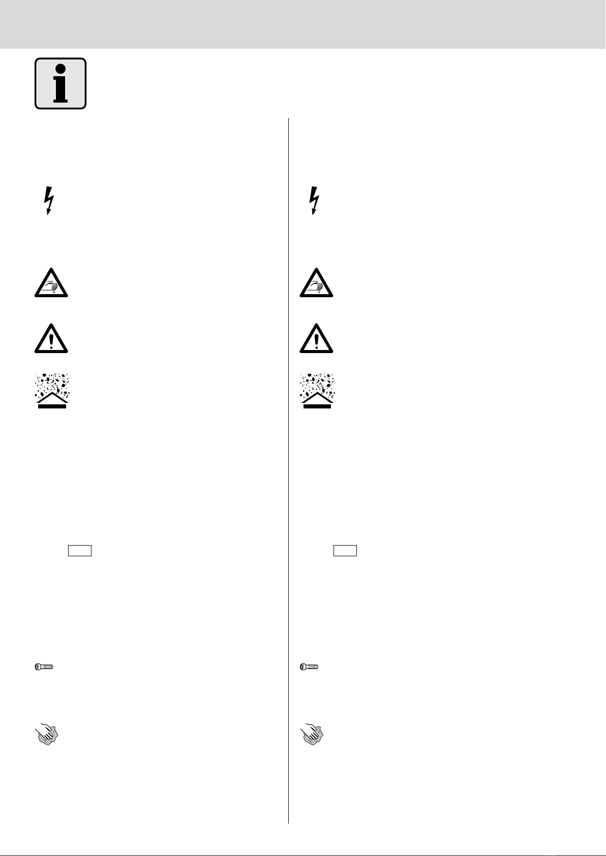
When lifting and carrying the dri-
ve unit, apply slings or supports only
as shown in illustration A or B. Take
note of the lengths given in the table.
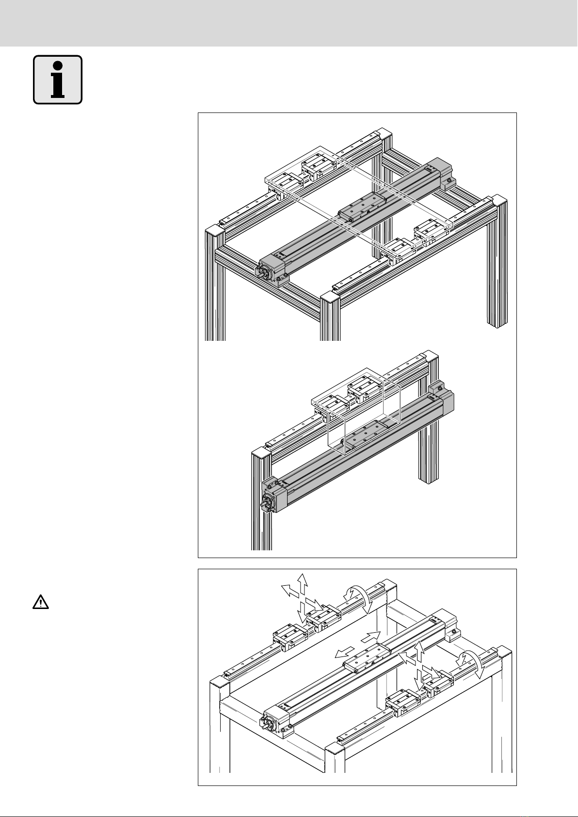
Do not exert force on the drive carria-
ge or protective profile.
Never suspend the AGK only by the
center of the protective profile or by
the ends!
When storing the drive unit, apply
sup-ports only to the two pillow blocks
(1). Do not apply any loads to the drive
carriage or the protective profile.
Store the drive unit in a roofed,
dry area. Protect from humidity and
corrosive agents.
1.2 Indications de sécurité
Les unités d’entraînement AGK
de Rexroth ne doivent être montées,
mises en service et entretenues que
selon les indications contenues dans
la présente notice d’instruction et
par un personnel spécialement for-mé
à cet effet, comme un électro-méca-
nicien.
Avant la première mise en
service de l’unité d’entraînement :
Réaliser des courses d’essai dans des
conditions proches de celles de la pro-
duction. Ne mettre l’installation avec
l’unité d’entraînement en fonctionnement
qu’après au moins un essai fructueux.
Vérifier la bonne assise de toutes les
fixations par vis.
1.3 Indications de transport
et de stockage
Les unités d’entraînement AGK de Rex-
roth sont livrées pré-assemblées
et prêtes au montage.
Ne solliciter l’unité d’entraîne-
ment que selon les schémas A ou B
lors de son levage ou de son trans-
port. Respecter les longueurs selon le
tableau. Ne pas solliciter les chariots
d’entraînement ou le profilé de pro-
tection.
Ne jamais suspendre au milieu du pro-
filé de protection ou aux extrémi-tés
de l’unité d‘entraînement AGK !
Lors de l’entreposage de l’unité d’en-
traînement AGK, ne la solliciter que
sur les deux boîtiers à palier (1). Ne
pas solliciter le chariot d’entraîne-
ment ou le profilé de protection.
Entreposer l’unité d’entraîne-
ment dans un local couvert et sec.
La protéger contre l’humidité et la
corrosion.
1.2 Avvertenze sulla sicurezza
Le unità di azionamento Rexroth
AGK devono essere montate, messe
in funzione e sottoposte a manuten-
zione solo da personale specializzato
in questo genere d’interventi, p. es.
operatori meccatronici.
Prima di iniziare con la messa in
funzione dell’unità di azionamento:
Eseguire corse di prova simulando le
condizioni di produzione. Mettere in fun-
zione l’impianto con l’unità di azionamen-
to soltanto se è stata effettuata almeno
una corsa di prova con risultato positivo.
Controllare che tutti i collegamenti a vite
siano serrati bene.
1.3 Avvertenze sul trasporto ed
il magazzinaggio
Le unità di azionamento Rexroth AGK
vengono fornite preassemblate e pronte
per il montaggio.
Nel sollevare e trasportare
l’unità di azionamento, trasportarla
soltanto come mostrano le figure A
e B. Rispettare le lunghezze in base
alla tabella. Non sollecitare le slitte
di azionamento ed il profilato di pro-
tezione.
Non sospendere mai soltanto al
centro del profilato di protezione o
soltanto alle estremità dell’unità di
azionamento AGK!
Quando si deposita a magazzino
l’unità di azionamento, sollecitarla
soltanto con entrambi i supporti
diritti (1). Non sollecitare la slitta
di azionamento ed il profilato di pro-
tezione.
Immagazzinare l’unità di
azionamento in ambiente coperto
e asciutto. Proteggere da umidità
e corrosione.
8Bosch Rexroth AG Antriebseinheit AGK | R310D4 3372 (2005.11)
2. Übersicht Antriebseinhei-
ten AGK
2.1 Typenübersicht
Rexroth Antriebseinheiten AGK sind in
drei Baugrößen erhältlich. Sie werden
einbaufertig vormontiert geliefert.
Genaue Daten und Maße siehe Katalog.
2.1
2.3
AGK 20-80
AGK 32-90
AGK 40-110
1
2
3
2.2
2.2 Baugruppen
Rexroth Antriebseinheiten AGK bestehen
aus den folgenden Baugruppen:
1Stehlager motorseitig, mit Festlager
2Schutzprofil mit Kugelgewindetrieb
und integrierten Spindelabstützungen
3Antriebsschlitten
4Abdeckband
5Stehlager mit Loslager
2.3 Typenschild, Bestellung von
Verschleißteilen
1Materialnummer* der Antriebseinheit
2Seriennummer
3Kundenauftragsnummer
4Fertigungsdatum
• Bei Bestellung von Verschleißteilen
bitte unbedingt alle Daten auf dem
Typenschild angeben.
* Die „Materialnummer“ kann in anderen
Druckschriften auch
„Teilenummer“ heißen.
145
60L60
100
145
70L60
110
18080L65
135
1
4
5
2
3
4
R310D4 3372 (2005.11) | Drive Unit AGK Bosch Rexroth AG 9
2. Overview,
Drive Units AGK
2.1 Type designations
Rexroth Drive Units AGK are available
in three sizes. They are delivered pre-as-
sembled and ready for installation.
The exact data and dimensions can be
found in the catalog.
2.2 Assemblies
Rexroth Drive Units AGK consist of the
following assemblies:
1Pillow block on motor side, with fixed
bearing
2Protective profile with ball screw drive
and integrated screw supports
3Drive carriage
4Sealing strip
5Pillow block with floating bearing
2.3 Nameplate, ordering of re-
placement parts
1Part number* of the drive unit
2Serial number
3Customer job number
4Date of manufacture
• When ordering wear parts, please
always state all data given on the
nameplate.
* In other publications, the “part num-
ber” may also be referred to
as “article number”.
2. Aperçu des unités
d’entraînement AGK
2.1 Aperçu des types
Les unités d’entraînement AGK de
Rexroth existent en trois tailles. Elles sont
fournies pré-assemblées et prêtes au
montage.
Pour les caractéristiques et dimensions,
voir le catalogue.
2.2 Ensembles
Les unités d’entraînement AGK de
Rexroth sont constituées des ensembles
suivants :
1Boîtier à palier fixe côté moteur
2Profilé de protection avec vis à billes
et supports de vis intégrés
3Chariot d’entraînement
4Bande de protection
5Boîtier à palier libre
2.3 Plaque signalétique, com-
mande de pièces d’usure
1Référence* de l’unité d’entraînement
2Numéro de série
3Référence commande client
4Date de fabrication
• Toujours indiquer les données figu-rant
sur la plaque signalétique lors
de la commande de pièces d’usure.
* Sur d’autres imprimés, « Référence»
peut s’appeler autrement («N° de
matériau» par exemple).
2. Prospetto delle unità di
azionamento AGK
2.1 Tipologia
Le unità di azionamento AGK sono di-
sponibili in tre grandezze. Esse vengono
fornite preassemblate e pronte per il
montaggio.
Per dati dettagliati e dimensioni fare
riferimento al catalogo.
2.2 Gruppi di componenti
Le unità di azionamento Rexroth AGK si
compongono dei seguenti componenti:
1supporti diritti lato motore, con cusci-
netto di vincolo assiale
2profilato di protezione con unità vite
a sfere e supporti vite integrati
3slitte di azionamento
4lamina di protezione
5supporto diritto con cuscinetto di
vincolo radiale
2.3 Targhetta di identificazione,
ordinazione di parti soggette
ad usura
1Numero identificativo* dell’unità di
azionamento
2Numero di serie
3Numero d’ordine del cliente
4Data di fabbricazione
• Quando si ordinano parti soggette ad
usura, indicare p.f. assolutamente tutti
i dati che si trovano sulla targhetta
d’identificazione.
* In altri cataloghi il « numero identifica-
tivo» può essere denominato anche
«numero di identificazione».
10 Bosch Rexroth AG Antriebseinheit AGK | R310D4 3372 (2005.11)
2.4
2.4 Montagevarianten
— Antriebsschlitten oben (1)
— Antriebsschlitten unten (ohne Abbil-
dung)
— Antriebsschlitten seitlich (2)
2.2
2.5 Hinweise zu Auslegung und
Belastungen
Das vorliegende System AGK ist
eine reine Antriebseinheit und nicht
zur Aufnahme von Auflagerkräften
oder Drehmomenten ausgelegt. Baus-
eitig sind geeignete Linearführungen
vorzusehen, die sämtliche Auflager-
kräfte, seitliche Kräfte und Drehmo-
mente aufnehmen. Der Antriebsschlit-
ten darf ausschließlich axiale Kräfte
aufnehmen.
1
2
F
F
M
M
F
F
M
M
R310D4 3372 (2005.11) | Drive Unit AGK Bosch Rexroth AG 11
2.4 Mounting options
— drive carriage at the top (1)
— drive carriage at the bottom
(no illustration)
— drive carriage at the side (2)
2.4 Variantes de montage
— Chariot d’entraînement sur le
dessus (1)
— Chariot d’entraînement en dessous
(sans illustration)
— Chariot d’entraînement monté latérale-
ment (2)
2.5 Indications relatives à la con-
ception et aux charges
Le système AGK est une unité
d’entraînement qui n’est conçue ni
pour l’absorption de forces verticales,
ni pour celle de couples. Il appartient
à l’utilisateur de prévoir les guidages
linéaires adéquats pouvant supporter
les forces verticales et latérales ainsi
que les couples. Le chariot d’entraîne-
ment ne doit supporter que des char-
ges axiales.
2.4 Varianti di montaggio
— Slitta di azionamento in alto (1)
— Slitta di azionamento in basso
(senza figura)
— Slitta di azionamento montata
lateralmente (2)
2.5 Notes on design and
permissible loads
The Drive Unit AGK is purely
a drive system and is not designed
to take up vertical or torsional loads.
When designing the machine or sys-
tem, linear guides should be provided
to take up all vertical, lateral and tor-
sional forces. The drive carriage may
only be subjected to axial forces.
2.5 Avvertenze su progetto
e carichi
Il sistema AGK è un’unità di azio-
namento e quindi non è concepi-ta per
l’assorbimento di forze verticali
o coppie. Da parte dell’utilizzatore si
devono prevedere guide lineari ade-
guate che possono supportare tutte
le forze verticali e laterali così come
le coppie. La slitta di azionamento
deve supportare esclusivamente forze
assiali.
12 Bosch Rexroth AG Antriebseinheit AGK | R310D4 3372 (2005.11)
3. Befestigung von Antriebs-
einheit und Kundenaufbau
3.1 Hinweise
Befestigungspunkte Antriebseinheit
3.1.1
3.1.2
max. 2500 mm
Schutzprofil abstützen
Unter dem Eigengewicht kann sich das
Schutzprofil durchbiegen.
• Ab einer freien Länge L von mehr als
2500 mm Auflagen für das Schutzpro-
fil vorsehen. !3.1.2
• Abstand zwischen den Auflagepunk-
ten max. 2500 mm.
• Auflageflächen der Schutzprofilaufla-
gen und der Stehlager sollten sich auf
einer Ebene befinden.
Im Betrieb hebt sich das Schutzprofil
bei Überfahren des Antriebsschlittens
und senkt anschließend wieder auf die
Auflagefläche ab.
• Auflageflächen der Schutzprofilauf-
lagen mit Dämpfung versehen, z. B.
Moosgummi-Matte aufkleben.
max. 2500 mm max. 2500 mm
max. 2500 mm max. 2500 mmmax. 2500 mm
Antriebseinheit ausschließlich
an den beiden Stehlagern befestigen.
Das Schutzprofil ist kein tragendes
Teil und darf daher keine Kräfte über-
tragen.
R310D4 3372 (2005.11) | Drive Unit AGK Bosch Rexroth AG 13
Provide supports for the protective
profile
The protective profile may deflect under
its own weight.
• For a free length L of more than
2500 mm, provide supports for the
protective profile. !3.1.2
• Distance between support points:
max. 2500 mm
• The mounting bases for the protective
profile supports and the pillow blocks
should be on the same level.
When the drive unit is in operation, the
protective profile lifts as the drive car-ria-
ge passes over it, then sinks back down
onto the supporting surface.
• Provide damping material on the
surfaces of the protective profile
supports, e.g. foam rubber pads.
Support du profilé de protection
Le profilé de protection peut fléchir sous
son propre poids.
• Prévoir des supports pour le profilé de
protection à partir d’une longueur L
supérieure à 2 500 mm. !3.1.2
• Ecartement maximum entre les points
de support : 2 500 mm.
• Les surfaces d’appui des supports
de profilé de protection et des boî-
tiers à palier doivent se trouver dans le
même plan.
En service, le profilé de protection se
soulève lors du passage du chariot
d’entraînement et redescend ensuite
sur la surface d’appui.
• Prévoir des amortisseurs sur la sur-
face d’appui, en collant par exemple
un coussin en caoutchouc cellulaire.
Supportare il profilato di protezione
Il profilato di protezione può flettersi sotto
il suo proprio peso.
• Prevedere sostegni per il profilato di
protezione a partire da una lunghezza
libera L superiore a 2500 mm.
!3.1.2
• Distanza massima tra i punti di soste-
gno: 2.500 mm.
• Le superfici d’appoggio dei sostegni
del profilato di protezione e dei sup-
porti diritti dovrebbero trovarsi sullo
stesso piano.
In fase di funzionamento, il profilato di
protezione si solleva al passaggio della
slitta di azionamento e poi si abbassa
nuovamente sulla superficie d’appoggio.
• Prevedere ammortizzatori sulle su-
perfici d’appoggio dei sostegni del
profilato di protezione incollandovi,
p. es., un feltro di gomma spugnosa.
3.
Mounting of the Drive
Unit and Customer Attach-
ments
3.1 Notes
Drive unit fastening points
3. Fixation de l’unité d’entraî-
nement et de la structure
client
3.1 Remarques
Points de fixation de l’unité d’entraî-
nement
3. Fissaggio dell’unità
di azionamento e del grup-
po del cliente
3.1 Avvertenze
Punti di fissaggio dell’unità di aziona-
mento
The drive unit may only be faste-
ned at the two pillow blocks.
The protective profile is not a load
bearing part and must not be used
to transmit forces.
Ne fixer l’unité d’entraînement
que sur les deux boîtiers à palier.
Le profilé de protection, qui n’est pas
une pièce portante, ne doit pas trans-
férer d’efforts.
Fissare l’unità di azionamento
esclusivamente con entrambi i sup-
porti diritti. Il profilato di protezione
non è un elemento portante e per-tan-
to non deve essere caricato con forze.
14 Bosch Rexroth AG Antriebseinheit AGK | R310D4 3372 (2005.11)
3.2 Antriebseinheit, Schienen-
führung und Kundenaufbau
ausrichten
Stehlager parallel zur Führung
ausrichten. Laufen Kugelgewindetrieb
und Führung nicht parallel, entstehen
im Betrieb Verspannungen und unzu-
lässige Radialkräfte.
• Bearbeitete Anschlagkanten an den
Stehlagern zur Ausrichtung verwen-
den.
H B
(mm) (mm)
AGK 20-80 100 35,0
AGK 32-90 110 30,0
AGK 40-110 135 37,5
3.2.2
Parallelität von Kundenaufbau,
Stehlagern und Schienenführungen
beachten.
3.2.1
H±0,01
II 0,01
II 0,01 B±0,01
II 0,01
R310D4 3372 (2005.11) | Drive Unit AGK Bosch Rexroth AG 15
3.2 Aligning the drive unit,
rail guide and customer at-
tachments
Align the pillow blocks parallel to
the guide. If the ball screw drive and
the guides are not parallel, inad-mis-
sible distortive stresses and radial
forces will occur during operation.
• Use the machined reference edges on
the pillow blocks for aligning.
H B
(mm) (mm)
AGK 20-80 100 35.0
AGK 32-90 110 30.0
AGK 40-110 135 37.5
Make sure the customer attach-
ments, pillow blocks and guide rails
are all parallel.
H B
(mm) (mm)
AGK 20-80 100 35,0
AGK 32-90 110 30,0
AGK 40-110 135 37,5
Vérifier le parallélisme de la
structure client, du boîtier à palier
et des rails de guidage.
3.2 Allineare l’unità di aziona-
mento, la guida su rotaia
ed il gruppo del cliente
Allineare i supporti diritti paral-
leli alla guida. Se non vi è paralleli-
smo tra l’unità vite a sfere e la guida,
durante il funzionamento si generano
serraggi eccessivi e forze radiali non
accettabili.
• Utilizzare per l’allineamento le super-
fici di riferimento sull’alloggiamento
dei supporti diritti.
H B
(mm) (mm)
AGK 20-80 100 35,0
AGK 32-90 110 30,0
AGK 40-110 135 37,5
Verificare il parallelismo del
gruppo del cliente, dei supporti diritti e
delle guide su rotaia.
3.2 Alignement de l’unité d’entraî-
nement, du rail de guidage et
de la structure client
Aligner le boîtier à palier parallè-
lement au guidage. Si la vis à billes et
le guidage ne sont pas parallèles, des
efforts radiaux non acceptables inter-
viennent lors du fonctionnement.
• Utiliser les bords de référence usinés
sur les boîtiers à palier pour l’aligne-
ment.
16 Bosch Rexroth AG Antriebseinheit AGK | R310D4 3372 (2005.11)
3.3 Stehlager befestigen
• Festlager an einer der beiden An-
schlagkanten ausrichten.
• Festlager mit Passstiften fixieren.
• Festlager mit 4 Schrauben befestigen,
dabei Unterlegscheiben nach DIN 125
verwenden.
Maße und Anziehdrehmomente siehe
Tabelle 3.3.3.
3.3.1
3.3.2
H
B
A
C
D
a
A
B
1
B
2
H
B
A
C
a
A
• Loslager an Anschlagkante auf der
gleichen Seite wie beim Festlager
parallel ausrichten.
• Loslager mit 2 Schrauben befesti-gen,
dabei Unterlegscheiben nach DIN 125
verwenden.
Maße und Anziehdrehmomente siehe
Tabelle 3.3.3.
A B B1B
2C D H S18.8 12.9
u(Nm) u(Nm)
AGK 20-80 120 145 60 10 28 40 10 9,7 M10 41 41
AGK 32-90 120 145 60 10 28 40 10 9,7 M10 41 41
3.4 Kundenaufbau befestigen
)Für größtmögliche Positionier-
genauigkeit den Antriebsschlitten
parallel zur Bewegungsrichtung des
Kundenaufbaus ausrichten.
Vor dem Befestigen des Kundenauf-
baus die Stehlager befestigen.
• Eine der beiden bearbeiteten An-
schlagkanten am Antriebsschlitten
zur Ausrichtung verwenden.
• Kundenaufbau mit 4 Schrauben am
Antriebsschlitten befestigen.
Maße und Anziehdrehmomente siehe
Tabelle.
E
1E
2S T 8.8 12.9
(mm) (mm) (mm) u(Nm) u(Nm)
AGK 20-80 60 60 M10 15 41 41
AGK 32-90 60 60 M10 15 41 41
AGK 40-110 80 80 M12 16 70 70
3.4
3.3.3
E2S x T
E1
S1
(mm)
R310D4 3372 (2005.11) | Drive Unit AGK Bosch Rexroth AG 17
3.3 Mounting the pillow block
• Align the fixed bearing with one of the
two reference edges.
• Secure the fixed bearing with straight
pins.
• Fix the fixed bearing in place with
4 screws using washers to DIN 125.
For dimensions and tightening torques,
see table 3.3.3.
• Align the floating bearing parallel with
the reference edge on the same side
as for the fixed bearing.
• Fix the floating bearing in place with
2 screws using washers to DIN 125.
For dimensions and tightening torques,
see table 3.3.3.
3.4 Mounting the customer at-
tachment
)To achieve the greatest possible
positioning accuracy, align the drive
carriage parallel to the direction of
motion of the customer attachment.
Screw down the pillow blocks before
fastening the customer attachment.
• Use one of the two machined refer-
ence edges on the drive carriage for
alignment.
• Screw the customer attachment down
on the carriage with 4 screws.
For dimensions and tightening tor-
ques, see table.
• Aligner le palier libre parallèlement sur
le bord de référence situé du même
côté que celui utilisé pour le palier
fi x e .
• Fixer le palier libre à l’aide de 2 vis en
utilisant des rondelles selon DIN 125.
Dimensions et couples de serrage voir le
tableau 3.3.3.
3.4 Fixation de la structure client
)Aligner le chariot d’entraînement
parallèlement au sens de déplace-
ment de la structure client pour obte-
nir une précision de position-nement
aussi grande que possible.
Fixer les boîtiers à palier avant de fixer
la structure client.
• Utiliser un des deux bords de réfé-
rence usinés sur le chariot d’entraî-ne-
ment pour l’alignement.
• Fixer la structure client sur le chariot
d’entraînement à l’aide de 4 vis.
Dimensions et couples de serrage voir
le tableau.
3.3 Fissare i supporti diritti
• Allineare il cuscinetto di vincolo
assiale ad una delle due superfici
di riferimento.
• Fissare il cuscinetto di vincolo assiale
con spine calibrate.
• Fissare il cuscinetto di vincolo assiale
con 4 viti utilizzando rondelle secon-
do DIN 125.
Per dimensioni e coppie di serraggio
vedere la tabella 3.3.3.
• Allineare il cuscinetto di vincolo
radiale parallelamente alla superficie
di riferimento situata sullo stesso lato
di quello utilizzato per il cuscinetto di
vincolo assiale.
• Fissare il cuscinetto di vincolo radiale
con 2 viti utilizzando rondelle secon-
do DIN 125.
Per dimensioni e coppie di serraggio
vedere la tabella 3.3.3.
3.4 Fissare il gruppo del cliente
)Allineare la slitta di azionamento
parallelamente al senso di sposta-
mento del gruppo del cliente per otte-
nere una precisione quanto maggiore
possibile.
Fissare i supporti diritti prima di pro-
cedere al fissaggio del gruppo del
cliente.
• Utilizzare per l’allineamento una delle
due superfici di riferimento elaborate
sulla slitta di azionamento.
• Fissare il gruppo del cliente con 4 viti
sulla slitta di azionamento.
Per dimensioni e coppie di serraggio
vedere la tabella.
3.3 Fixation des boîtiers à palier
• Aligner le palier fixe sur l’un des deux
bords de référence.
• Maintenir le palier fixe en position par
goupilles.
• Fixer le palier fixe à l’aide de 4 vis en
utilisant des rondelles selon DIN 125.
Dimensions et couples de serrage voir le
tableau 3.3.3.
18 Bosch Rexroth AG Antriebseinheit AGK | R310D4 3372 (2005.11)
4.1
4. Anbauteile
Auf Wunsch können folgende Kom-
ponenten bei der Bosch Rexroth AG
einsatzfertig montiert werden.
Schaltsystem mit Magnetfeldsensoren
!5.
1Dose mit Stecker, 16-polig
2Schalter (maximal 3)
Schalter und Dose können jederzeit
nachgerüstet werden. Sofern erforder-
lich, kann der Schaltpunkt nachträglich
verschoben werden.
Antrieb !6.
3Motor
4Riemenvorgelege
5Flansch und Kupplung
Nachrüstung ist ebenfalls jederzeit
möglich.
4
3
3
5
1
2
R310D4 3372 (2005.11) | Drive Unit AGK Bosch Rexroth AG 19
4. Equipements périphériques
Sur demande, les composants suivants
peuvent être montés prêts à l’utilisation
chez Bosch Rexroth AG.
Système de commutation à capteurs
de champ magnétique !5.
1Prise avec fiche, 16 pôles
2Commutateurs (3 au maximum)
Les commutateurs et la prise peuvent
être rééquipés à tout moment. Le cas
échéant, le point de commutation peut
être déplacé.
Entraînement !6.
3Moteur
4Renvoi par poulie et courroie
5Lanterne et accouplement
Le rééquipement est également possible
à tout moment.
4. Attachments
If desired, the following components
can be mounted ready for use before
shipment by Bosch Rexroth AG.
Switching system with magnetic field
sensors !5.
116-pin plug with socket
2Switches (maximum of 3)
The switches and socket can be retro-
fitted at any time. If necessary, the switch
activation point can be adjusted later.
Drive !6.
3Motor
4Timing belt side drive
5Motor mount and coupling
Retrofitting of these components is also
possible at any time.
4. Accessori
Su richiesta è possibile assemblare i
seguenti componenti presso la Bosch
Rexroth AG pronti per il montaggio.
Sistema interruttori con sensori
a campo magnetico !5.
1Presa con spina, 16 poli
2Interruttori (massimo 3)
È possibile cambiare la posizione di in-
terruttori e presa in qualsiasi momento.
Se necessario, l’interruttore può essere
spostato successivamente.
Azionamento !6.
3Motore
4Trasmissione a cinghia e puleggia
5Flangia e giunto
Anche qui il cambiamento della posi-
zione è possibile in qualsiasi momento.
20 Bosch Rexroth AG Antriebseinheit AGK | R310D4 3372 (2005.11)
5. Schaltsystem mit Magnet-
feldsensoren
5.1 Hinweise
Voraussetzung für den Einbau des
Schaltsystems ist die Befestigung der
Antriebseinheit auf dem Unterbau.
Der Schalteranbau ist nur auf einer Seite
der Antriebseinheit zulässig.
Stromversorgung unterbrechen!
5.2.1
3
2
1
5.2 Magnetfeldsensor einbauen
• Sensor (1) mit Gewindestift (2) nach
außen in die obere T-Nut des Gehäu-
ses einführen.
• Schaltpunkt einstellen und Sensor mit
Gewindestift (2) fixieren.
• Die Signalleitung (3) in die obere
oder untere Kabelführung der T-Nut
eindrücken und dadurch fixieren.
3
1

This manual suits for next models

2

Other Bosch DC Drive manuals

Bosch Performance Line Cargo User manual

Bosch

Bosch Performance Line Cargo User manual

Bosch REXROTH IndraDrive Technical manual

Bosch

Bosch REXROTH IndraDrive Technical manual

Bosch Rexroth Sytronix FcP 5020 User manual

Bosch

Bosch Rexroth Sytronix FcP 5020 User manual

Bosch BDU3740 User manual

Bosch

Bosch BDU3740 User manual

Bosch BDU490P User manual

Bosch

Bosch BDU490P User manual

Bosch Active Line User manual

Bosch

Bosch Active Line User manual

Bosch Rexroth Sytronix SvP 7020 PFC User manual

Bosch

Bosch Rexroth Sytronix SvP 7020 PFC User manual

Bosch Rexroth IndraDrive HMV01.1E-W0030 Technical manual

Bosch

Bosch Rexroth IndraDrive HMV01.1E-W0030 Technical manual

Bosch Rexroth IndraDrive Series Instructions for use

Bosch

Bosch Rexroth IndraDrive Series Instructions for use

Bosch BDU450 CX User manual

Bosch

Bosch BDU450 CX User manual

Bosch Active Line Plus BDU 350: 0 275 007 047 User manual

Bosch

Bosch Active Line Plus BDU 350: 0 275 007 047 User manual

Bosch BDU3741 User manual

Bosch

Bosch BDU3741 User manual

Bosch Rexroth EFC 3600 Instructions for use

Bosch

Bosch Rexroth EFC 3600 Instructions for use

Bosch Rexroth AOK User manual

Bosch

Bosch Rexroth AOK User manual

Bosch Rexroth Hagglunds DOb Manual

Bosch

Bosch Rexroth Hagglunds DOb Manual

Bosch 0 275 007 038 User manual

Bosch

Bosch 0 275 007 038 User manual

Bosch BDU480 CX User manual

Bosch

Bosch BDU480 CX User manual

Bosch REXROTH IndraDrive Mi KSM01 User manual

Bosch

Bosch REXROTH IndraDrive Mi KSM01 User manual

Bosch rexroth Sytronix SvP 7030 IMC User manual

Bosch

Bosch rexroth Sytronix SvP 7030 IMC User manual

Bosch Active Line Plus BDU 350 User manual

Bosch

Bosch Active Line Plus BDU 350 User manual

Bosch Rexroth ROTATRAC eGFT 8000 10 Series User manual

Bosch

Bosch Rexroth ROTATRAC eGFT 8000 10 Series User manual

Bosch Classic+ Line 0 275 007 003 User manual

Bosch

Bosch Classic+ Line 0 275 007 003 User manual

Bosch Rexroth EFC 3600 User manual

Bosch

Bosch Rexroth EFC 3600 User manual

Bosch BDU350 User manual

Bosch

Bosch BDU350 User manual

Popular DC Drive manuals by other brands

schmalenberger 27217-A Operator's manual

schmalenberger

schmalenberger 27217-A Operator's manual

ABB ACS355 series Quick installation and start-up guide

ABB

ABB ACS355 series Quick installation and start-up guide

Parker GT6-L8-NK Hardware installation guide

Parker

Parker GT6-L8-NK Hardware installation guide

Nidec Digitax ST Series installation guide

Nidec

Nidec Digitax ST Series installation guide

Allen-Bradley PowerFlex 70 Quick start quide

Allen-Bradley

Allen-Bradley PowerFlex 70 Quick start quide

Festo EMCS-ST operating instructions

Festo

Festo EMCS-ST operating instructions

YASKAWA JVOP-181 Driver installation guide

YASKAWA

YASKAWA JVOP-181 Driver installation guide

Danfoss VLT AutomationDrive FC 300 Design guide

Danfoss

Danfoss VLT AutomationDrive FC 300 Design guide

Siemens SINAMICS G120P Hardware installation manual

Siemens

Siemens SINAMICS G120P Hardware installation manual

Lenze AC Tech MCH Series reference guide

Lenze AC Tech

Lenze AC Tech MCH Series reference guide

ABB ACS355 series Quick installation and start-up guide

ABB

ABB ACS355 series Quick installation and start-up guide

Parker 650 Series Easy start guide

Parker

Parker 650 Series Easy start guide

KB Electronics KBAC-24D Installation and operation manual

KB Electronics

KB Electronics KBAC-24D Installation and operation manual

eldoLED LINEARdrive 720D quick start guide

eldoLED

eldoLED LINEARdrive 720D quick start guide

YASKAWA GA800 Series installation manual

YASKAWA

YASKAWA GA800 Series installation manual

GFA ELEKTROMAT SI 5.250 FU-25,40 installation instructions

GFA

GFA ELEKTROMAT SI 5.250 FU-25,40 installation instructions

Rockwell Automation Allen-Bradley 160 SSC Series user manual

Rockwell Automation

Rockwell Automation Allen-Bradley 160 SSC Series user manual

Lenze 8200 motec Mounting instructions

Lenze

Lenze 8200 motec Mounting instructions

manuals.online logo
manuals.online logoBrands
  • About & Mission
  • Contact us
  • Privacy Policy
  • Terms and Conditions

Copyright 2025 Manuals.Online. All Rights Reserved.