3
Avoiding General Hazards
Do not use the dishwasher until it is completely
installed. When opening the door on an uninstalled
dishwasher, carefully open the door while supporting
the rear of the unit. Failure to follow this warning can
cause the dishwasher to tip over and result in serious
injury.
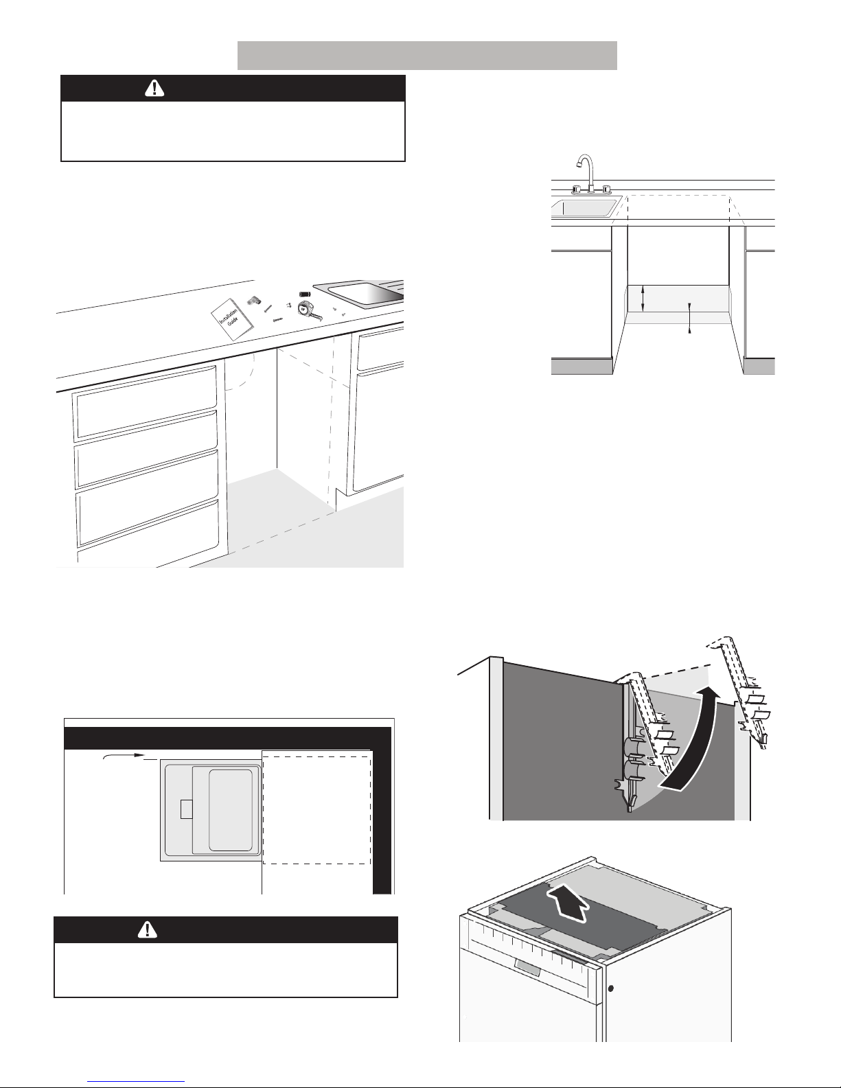
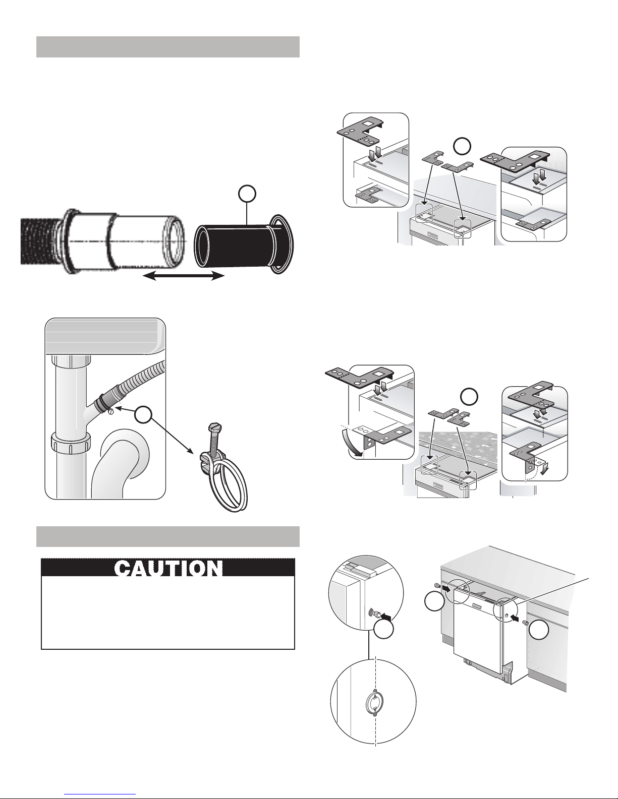
Before installing the “L”-shaped supplied countertop
mounting brackets (select models), decide which
method will be used to secure the dishwasher into its
opening. Once these mounting brackets are installed
RQWKHGLVKZDVKHUUHPRYLQJWKHPLVGLI¿FXOWDQGZLOO
damage the mounting brackets and the dishwasher.
In some conditions, hydrogen gas can form in a hot
water system that has not been used for weeks.
Hydrogen gas is explosive.
%HIRUH ¿OOLQJ D GLVKZDVKHU IURP D V\VWHP WKDW KDV
been off for weeks, run the water from a nearby faucet
in a well ventilated area until there is no sound or evi-
dence of gas.
Temperatures required for soldering and sweating will
damage the dishwasher’s base and water inlet valve.
If plumbing lines are to be soldered or sweated, keep
the heat source at least 6Ǝ(152.4 mm) away from the
dishwasher’s base and water inlet valve.
Removing any cover or pulling the dishwasher from the
cabinet can expose hot water connections, electrical
power and sharp edges or points. Handle with care.
Avoiding Electrical Shock/Fire Hazards
Do not allow the electrical and water supply lines to
touch. Separate channels are provided under the
dishwasher.
Do not work on an energized circuit. Doing so could
UHVXOWLQVHULRXVLQMXU\RUGHDWK2QO\TXDOL¿HGHOHFWUL-
cians should perform electrical work. Do not attempt
any work on the dishwasher electric supply circuit
until you are certain the circuit is de-energized.
0DNHVXUHHOHFWULFDOZRUNLVSURSHUO\LQVWDOOHG7KHUH
should be no loose electrical connections. Ensure all
electrical connections are properly made.
The customer has the responsibility of ensuring that the
dishwasher electrical installation is in compliance with
all national and local electrical codes and ordinances.
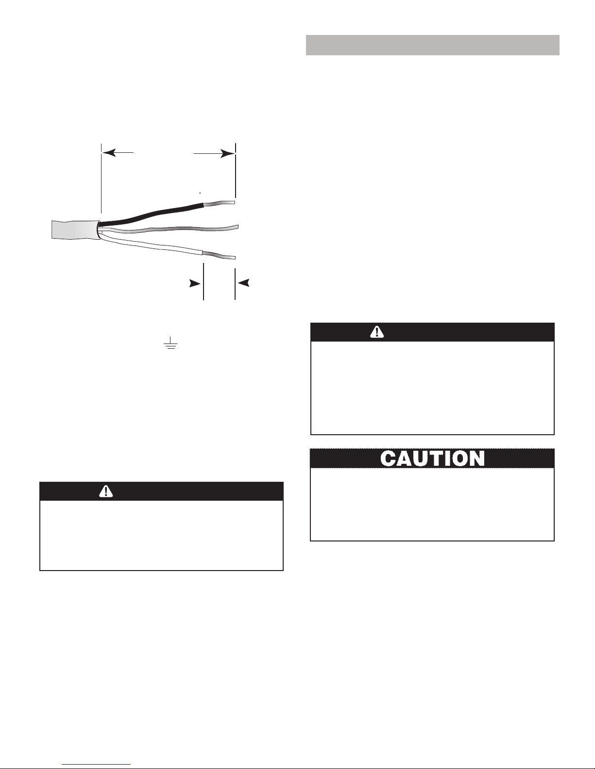
The dishwasher is designed for an electrical supply
of 120V, 60 Hz, AC, connected to a dishwasher-
dedicated, properly grounded electrical circuit with a
fuse or breaker rated for 15 amps. Electrical supply
conductors shall be a minimum #14 AWG copper only
wire rated at 75°C (167°F) or higher.
This appliance must be connected to a grounded metal,
permanent wiring system, or an equipment-grounding
conductor must be run with the circuit conductors and
connected to the equipment-grounding terminal or
lead on the appliance. Do not use extension cords.
Avoiding Plumbing/Scalding Hazards
Do not perform any work on a charged hot water line.
6HULRXVLQMXU\FRXOGUHVXOW2QO\TXDOL¿HGSOXPEHUVKRXOG
perform plumbing work. Do not attempt any work on
the dishwasher hot water supply plumbing until you
are certain the hot water supply is shut off.
Do not over tighten the 90° elbow. Doing so may
damage the water inlet valve and cause a water leak.
Temperatures required for soldering and sweating
will damage the dishwasher’s water inlet valve. If
plumbing lines are to be soldered or sweated, keep
the heat source at least 6Ǝ(152.4 mm) away from the
dishwasher’s water inlet valve.
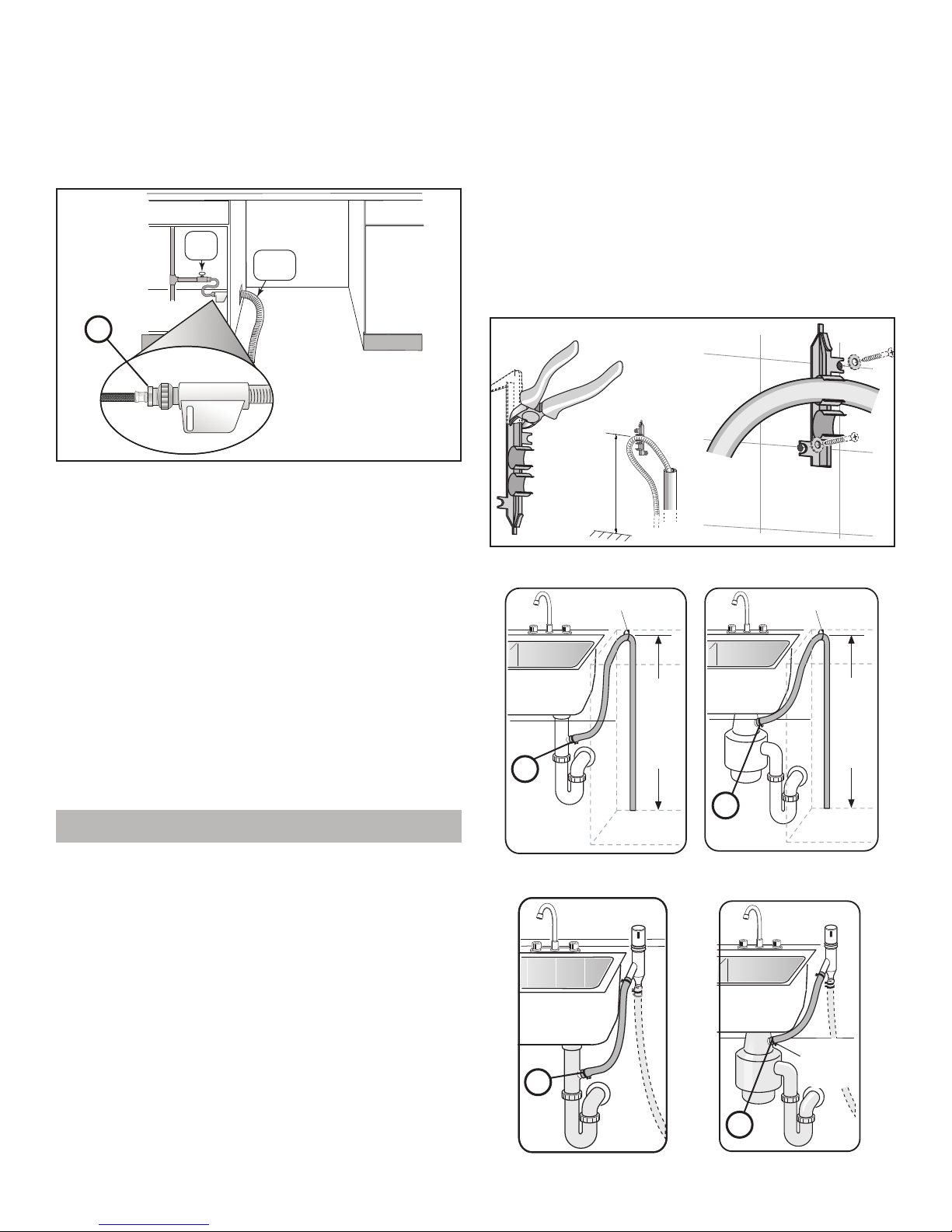
Check local plumbing codes for approved plumbing
procedures and accessories. All plumbing should be
done in accordance with national and local codes.
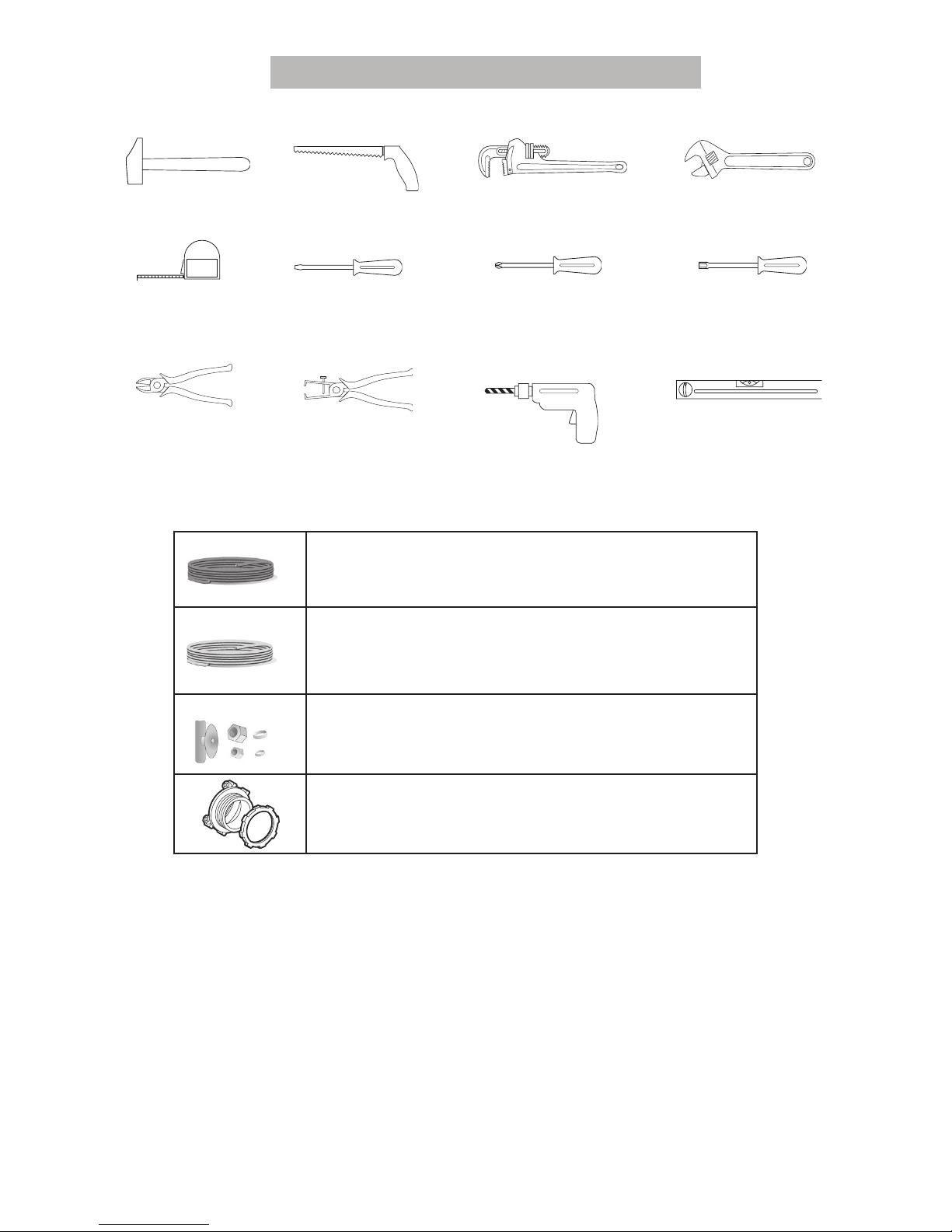
These instructions depict an installation method for
VWDLQOHVVVWHHOEUDLGHGKRVHRU3(;KRWZDWHUVXSSO\
lines. If using copper tubing or other material for
water supply, defer to a licensed plumber for proper
installation.
WARNING