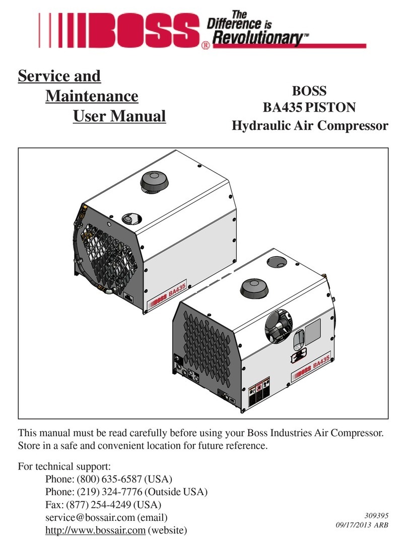
Boss Industries INFINITY 35 User manual

310928
8/23/2016 AEM
http://www.bossair.com
Product Manual
INFINITY 35
Hydraulically Driven Air Compressor
This manual must be read carefully before using your Boss Industries, LLC INFINITY 35. Store in a safe
and convenient location for future reference.

- 2 - 310928

- 3 - 310928
Contents
Welcome...............................................4
General Information.........................................4
Safety....................................................5
General Safety Overview.................................5
Safety Precautions...........................................6
Specifications......................................8
Specification Sheet..........................................8
Installation & Operation......................9
Mounting the Compressor................................9
Installation of Air Storage Tanks....................10
Installation of Wiring.......................................10
Connecting the Hydraulic Hoses....................11
Pre-Start-up Inspection Checks.....................11
Check All Fluid Levels....................................11
Machine Documentation................................11
Lifetime Warranty Registration.......................11
Shutdown Procedure.....................................12
Operating Conditions.....................................12
Operating Procedure......................................12
Maintenance.......................................13
Lifetime Warranty Information........................13
Recommended Spare Parts List....................13
Maintenance Chart.........................................14
Compressor Oil..............................................15
Compressor Oil Fill, Level, and Drain............16
Changing the Oil Filter...................................16
Changing the Air/Oil Coalescer......................17
Changing the Air Intake Filter........................17
Compressor Drive Belts.................................18
Troubleshooting................................19
Improper Discharge Pressure........................19
Sump Pressure Does Not Blow Down...........19
Oil Consumption.............................................19
Coalescer Plugging........................................20
High Compressor Discharge Temperature....20
Contacting Boss Industries, LLC....................20
Warranty.............................................21

- 4 - 310928
Welcome
General Information
Thank you for choosing the Boss Industries, LLC
INFINITY 35 Hydraulically Driven Air Compressor.
Before operating, carefully read this manual and
become well acquainted with your new machine.
Doing this will increase your safety and maximize
the life of the machine.
While this manual is written to be as accurate as
possible, Boss Industries, LLC strives to continually
improve the efficiency and performance of its
machines. As a result, sometimes there may be slight
differences between a given version of the manual
and the machine.

- 5 - 310928
Safety
General Safety Overview

- 6 - 310928
Safety
Safety Precautions
The following safety precautions are a general guide to safe operation of the equipment.

- 7 - 310928
Safety
Safety Precautions (continued)

- 8 - 310928
Specifications
Specification Sheet
COMPRESSOR SPECIFICATIONS
Model INFINITY 35
Type Hydraulically Driven Air Compressor
Output
Compressor RPM
Hyd Flow Hyd Pressure
Delivery
20 CFM @ 110 PSI 4400 8.2 GPM 1500 PSIG
25 CFM @ 110 PSI 5400 10.1 GPM 1500 PSIG
30 CFM @ 110 PSI 6400 12.0 GPM 1500 PSIG
35 CFM @ 110 PSI 7200 13.5 GPM 1500 PSIG
35 CFM @ 150 PSI 7300 13.7 GPM 1800 PSIG
35 CFM @ 175 PSI 7400 14.0 GPM 2100 PSIG
Operating Pressure
Range 80 - 175 PSIG
Ambient Operating
Temperature Range -20° - 110°F
Oil Capacity
(Compressor) 1 gallon
Air Service Connection 1/2” NPT
Overall Dimensions 28.89” L X 19.34” W X 21.82” H
Weight 200 lbs.
*CALCULATIONS PERFORMED @ 85% EFFICIENCY MECHANICAL AND 96% EFFICIENCY
VOLUMETRIC.
SPECIFICATIONS SUBJECT TO CHANGE WITHOUT PRIOR NOTICE

- 9 - 310928
Installation & Operation
Mounting the Compressor
When mounting the compressor, care should be taken
to ensure that its location does not impede the
operation of other components on the vehicle. For
example, if your vehicle is equipped with a crane, you
must make sure the compressor will not interfere with
the swing of the crane. In addition, the compressor
should be installed in an area that permits cool
ambient air to enter the air filter and the hot air to
exhaust without recirculating into the machine. A
minimum of 12” of clearance is needed for the hot
discharge air from the cooler. A minimum of 10” of
clearance is required from the rear of the compressor
to allow for proper air intake. Cool ambient air is
drawn in from the rear of the machine. One last
consideration in the mounting should be the routing
of hydraulic hoses. Be sure these can be safely run
to the hydraulic manifold on the machine. The unit
should be secured to the vehicle with four 3/8” grade
8 bolts, flat washers, and loc washers. Ensure that
you have a sub structure that will support the weight
of the compressor. Be sure to follow all National
Vehicle Safety Standards.

- 10 - 310928
Installation of Air Storage Tanks
This rotary screw air compressor system is designed
to provide continuous volume and constant pressure
without the use of an air storage tank. Within a few
seconds of engagement, the compressor will produce
full volume and pressure needed to run corresponding
air operated equipment without waiting for air tanks
to fill.
Air storage tanks are not utilized as standard
equipment on vehicle mounted rotary screw
compressors. The installation of air storage tanks, if
not done properly, will hinder the performance of the
rotary screw compressor. Boss Industries, LLC
strongly discourages the use of an air storage tank as
standard equipment for vehicle mounted rotary screw
air compressors.
In the rare event air usage is required without
operating the vehicle, an air storage tank can be added
to your system. When adding an air storage tank, be
sure to follow all state and federal DOT regulations
regarding air storage tank usage.
Installation of Wiring
This unit is shipped from the factory with all
necessary internal wiring installed. The only
remaining wiring necessary is the wiring needed to
interface your vehicle/power source with the Boss
compressor. The unit is shipped with 1 end of a 4 pin
connector. They need to be connected as follows:
Pin A) Battery Power
Pin B) Power out to hydraulic system solenoid
through safeties
Pin C) Battery Ground
Pin D) 12VDC switched power for operation
Pin ‘B’ should be used to direct hydraulic flow to the
compressor. This wire can also be used with a relay
to signal the engine speed to increase if additional
hydraulic flow is required during compressor
operation. See one example below.
Installation & Operation

- 11 - 310928
HYD PRESSURE IN
-10 SAE
5/8" MIN HOSE ID
HYD RETURN OUT
-16 SAE
1" MIN HOSE ID
ELECTRICAL CONNECTION AIR OUTLET
1/2" FNPT
COMPRESSOR
OIL FILL
Installation & Operation
Connecting the Hydraulic Hoses
The hydraulic hoses to the compressor should be
connected directly to the hydraulic manifold with
appropriately sized fittings. The input line should be
made from a good quality high pressure (min. 3000
PSI) hydraulic hose 5/8" i.d. The return line can be
made from a medium pressure (min 1500 psi)
hydraulic hose 1" i.d. Care should be taken to see
that the hoses are not installed with kinks or bends
that inhibit flow of the hydraulic oil. Lack of flow
could result in damage to the motor and compressor.
Lastly, check to make sure hoses are not in contact
with sharp objects or edges that may fray, chafe, or
cut them over time. Secure all hoses with tie down
straps or clamps.
Pre-Start-up Inspection Checks
This inspection should be done prior to the
compressor test.
I. Check all assemblies, clamps, fittings, hose
connections, nuts, and bolts to ensure they are
properly tied and secured to the vehicle. This
is a very critical area of inspection. The
vehicle should not be moved until this
inspection has been completed.
II. Remove all tools, rags, and installation
equipment from the area.
III. Check all valves to ensure they are in correct
operating position.
IV. Vacuum all areas that have metal or plastic
shavings. Wipe all fingerprints off unit and
vehicle.
Check All Fluid Levels
Position the unit on a level surface so that proper
amount of fluids can be added.
I. Check the compressor oil level.
A. Add oil if needed.
B. Additional oil may need to be added after
test.
C. Top off oil level to half the sightglass
when finished with the test.
II. Check hydraulic system oil level.
Machine Documentation
Record all serial numbers for this installation.
A. Boss Industries, LLC Serial Number
_________________________________________
B. Compressor Serial Number
_________________________________________
C. Note any special applications relating to
specific installations.
_________________________________________
_________________________________________
Lifetime Warranty Registration
Every Boss Industries, LLC INFINITY 35 machine
comes standard with a lifetime warranty on the airend.
In order to activate the lifetime coverage, the
customer must register the machine on the following
website: www.bossair.com/lw

- 12 - 310928
Installation & Operation
Shutdown Procedure
I. Close service valve.
II. Disengage hydraulic flow to compressor.
III. Disengage hydraulic system.
Operating Conditions
The following conditions should exist for maximum
performance of the compressor:
●The machine should be as close to level as
possible when operating.
●Ambient temperature for operation should be
below 110°F (43°C). The machine may
experience high temperature shutdown above
this level.
Operating Procedure
I. Read this manual carefully before proceeding.
II. Verify the service valve is closed.
III. Engage hydraulic system.
IV. Allow hydraulic system to run on bypass for
3-5 minutes to warm-up.
V. Engage hydraulic flow to compressor.
VI. Allow compressor speed to stabilize before
opening service valve for use.

- 13 - 310928
Maintenance
Lifetime Warranty Information
In order to maintain the lifetime warranty status on
your INFINITY 35, the required maintenance
intervals listed on the following page must be obeyed.
Recommended Spare Parts List
PART
NUMBER DESCRIPTION
310438 Air Filter Element
80384 50-Hour Maintenance
Kit
80385 1-Year or 500-Hour
Maintenance Kit

- 14 - 310928
Maintenance Chart
The MAINTENANCE CHART lists serviceable items on this compressor package. The items are listed
according to their frequency of maintenance.
Maintenance
INTERVAL REQUIRED MAINTENANCE
EVERY 10 HOURS OR
DAILY
1. Check compressor oil level.
2. Check for oil and air leaks.
3. Check compressor air filter maintenance indicator. Clean or
change filter as required.
EVERY 50 HOURS OR
WEEKLY
1. Drain liquid from compressor sump. More frequent draining
may be required under high humidity conditions.
2. Inspect compressor mounting bolts.
*3. After first 50 hours install Boss P/N 80384 50-Hour
Maintenance Kit. Steps include changing oil and oil filter element.
Then follow yearly maintenance schedule.
EVERY 250 HOURS
OR 6 MONTHS
1. Check compressor shaft seal for leakage.
2. Check compressor air filter connections, fittings, and clamps.
EVERY 500 HOURS
OR 1 YEAR
1. Install Boss P/N 80385 1-Year or 500-Hour Maintenance Kit.
Steps include changing oil, oil filter element, air/oil coalescing
element, and air filter element.
2. Check airend pressure relief valve.
3. Clean cooler fins on all coolers.

- 15 - 310928
Maintenance
Compressor Oil

- 16 - 310928
Maintenance
Compressor Oil Fill, Level, and
Drain
Before adding or changing compressor oil, make sure
that the compressor is completely relieved of pressure.
The drain is located on the rear of the machine
towards the bottom of the airend. To drain the oil,
remove the cap from the oil drain hose and rotate the
valve to the open position to release all of the oil from
the compressor sump. When oil has been drained,
rotate the valve to the closed position and reinstall the
cap on the end of the hose.
Oil is added at the fill cap on the side of the machine.
The proper oil level is in the middle of the oil
sightglass when the unit is shut down and has had
time to settle. The machine must be level when
checking the oil. The fill neck is designed to prevent
overfilling; however, care must still be taken to ensure
the proper oil level. DO NOT OVERFILL. The oil
capacity is given in “Compressor Specifications”.
Changing the Oil Filter
The oil filter is a spin-on type element that is easily
replaced through the maintenance access panel. First,
remove the access panel from the right side (by the
pressure gauge) of the machine by removing the 2
bolts securing it. Inside the access panel will be 2
spin-on filter elements: the oil filter and the air/oil
coalescer. The oil filter will be on the left side and is
the smaller of the 2 filters. To remove the old
element, turn it counter-clockwise until it is loose and
then lift it off of the stem and out of the access panel.
It is normal for this filter to drip oil when it is
removed. You may need the assistance of a band
wrench to remove the old element, but new elements
should be installed by hand tightening only. Once
the old element is out, put a film of oil on the rubber
ring of the new element and place it onto the stem and
turn clockwise with your hands until it is tight. The
element should spin on very freely until the last full
turn. Make sure the threads are engaging properly if
it does not spin freely. Once the new element has
been installed, reinstall the access panel using the 2
bolts that were previously removed.

- 17 - 310928
Maintenance
Changing the Air/Oil Coalescer
The air/oil coalescer is a spin-on type element that is
easily replaced through the maintenance access panel.
First, remove the access panel from the machine by
removing the 2 bolts securing it. Directly inside the
opening you will find the air/oil coalescer. This is
the larger of the 2 spin-on elements. To remove the
old element, turn it counter-clockwise until it is loose,
and then lift it off of the stem and out of the access
panel. It is normal for this filter to drip oil when it is
removed. You may need the assistance of a band
wrench to remove the old element, but new elements
should be installed by hand tightening only. Once
the old element is out, put a film of oil on the rubber
ring of the new element and place it onto the stem and
turn clockwise with your hands until it is tight. The
element should spin on freely until the last full turn.
Make sure the threads are engaging properly if it does
not spin freely. Once the new element has been
installed, reinstall the access panel using the 2 bolts
that were previously removed.
Changing the Air Intake Filter
The air intake filter is a heavy-duty dry type high
efficiency filter designed to protect the compressor
from dust and foreign objects.
Frequency of maintenance of the filter depends on
dust conditions at the operating site. The filter
element must be serviced when clogged. A clogged
air filter element will reduce compressor performance
and cause premature wear of components.
To change the air filter element, first remove the
maintenance access panel from the machine by
removing the 2 bolts securing it. Make sure the
machine is not running when you perform this or any
other maintenance. Inside the access panel you will
find an air filter assembly with 2 latches. Disengage
each latch and pull the end cover off of the air filter
assembly. Inside you will find the air filter element.
Remove the air filter element by pulling and gently
twisting. Install the new filter element in reverse
fashion. Reinstall the air filter assembly end cover
and latch both latches to ensure a tight seal on the
element inside. Reset the air filter maintenance
indicator located on the air filter outlet. Once the new
element has been installed, reinstall the access panel
using the 2 bolts that were previously removed.

- 18 - 310928
Maintenance
Compressor Drive Belts
The 2-belt arrangement is sized for an average life of
1000 hours. This time frame can be increased or
decreased depending on the end user’s periodic
maintenance schedule. Drive belt tension should be
checked for adjustment after the first 10 hours of
operation and checked for adjustment every 100 hours
there after. Belt deflection is to be checked at
midpoint between both pulleys on one belt at a time.
Single belt deflection is to be 1/8” at 2.7 lbs.
minimum to 3.3 lbs. maximum.
The belt tension can be adjusted according to the
following procedure:
●Loosen 1/2” bolt that attaches the hydraulic motor
mounting bracket to the compressor base plate.
●Loosen 3/8” jam nut on the turnbuckle assembly.
●Loosen 3/8” nuts at the top and bottom eyebolts.
●Rotate turnbuckle nut clockwise to increase belt
tension and counterclockwise to decrease belt
tension.
●Tighten all nuts and bolts in reverse order.

- 19 - 310928
Troubleshooting
Improper Discharge Pressure
If discharge pressure is too low, check the following:
I. Too much air demand. (Air tools required
more air than the compressor can produce, air
tools are free wheeling without resistance.)
II. Service valve is wide open to atmosphere.
III. Leaks in service line.
IV. Restricted compressor inlet air filter.
V. Faulty control system operation (i.e. regulator
is sending a signal to close the inlet valve at
all times).
If discharge pressure is too high or the safety valve
blows, check the following:
I. Coalescer plugged or blocked.
II. Faulty safety valve.
III. Faulty regulator (regulator air pressure signal
is not getting to inlet valve).
If pressure relief valve blows at compressor idle,
check the following:
I. Inlet valve leaking or open.
II. Faulty regulator.
Sump Pressure Does Not Blow
Down
If after the compressor is shutdown, pressure does not
automatically blow down (this process should take
about 1 minute), check for:
I. Blow down valve may be inoperative.
II. Blow down valve exhaust port plugged. Blow
down valve should have a 3/64” orifice fitting
that is installed in the exhaust port.
Oil Consumption
Abnormal oil consumption or oil in service line can
be caused by the following:
I. Overfilling of oil sump.
II. Leaking oil lines or oil cooler.
III. Defective coalescer element.
IV. Compressor shaft seal leakage.
V. Discharge pressure below 65 PSI or above
150 PSI.
Relieving pressure too quickly after shutdown will
cause the oil to foam and spill out of the blow down
valve.

- 20 - 310928
Troubleshooting
Coalescer Plugging
If the coalescer element has to be replaced frequently
because it is plugging, it is an indication that foreign
material may be entering the compressor inlet or the
compressor oil is breaking down.
Compressor oil can break down prematurely for a
number of reasons:
I. Extreme operating temperature.
II. Negligence in draining condensate from oil
sump.
III. Using the improper type of oil or dirty oil.
High Compressor Discharge
Temperature
If the compressor shuts down on high temperature,
check the following:
I. Check compressor oil level. Add oil if
required.
II. Clean outside of oil cooler.
III. Clean oil system (cooler) internally.
IV. Check fan switch/relay harness. Fan should
be running at all times when compressor is
spinning.
Contacting Boss Industries, LLC
If you need assistance with any of the preceding steps,
or cannot find the solution to your problem, call the
Boss Industries, LLC Service Department.
Phone: (800)635-6587 (USA)
Phone: (219)324-7776 (Outside USA)
Fax: (877)254-4249
Email: [email protected]
Website: http://www.bossair.com
When calling for technical support, have the
following information available:
Machine Serial Number
Description of the problem
Table of contents
Other Boss Industries Air Compressor manuals
Popular Air Compressor manuals by other brands
Becker
Becker DT 4.25 Translation of the operating instructions
Craftsman
Craftsman 919.16558 owner's manual
XTline
XTline XT2002 user manual
Stanley
Stanley Fatmax TAB 200/10/24V Instruction manual for owner's use

Grizzly
Grizzly G0467 Parts Breakdown
Clarke
Clarke BOXER 14/150P Operation & maintenance instructions
