Boss Industries BA435 Piston Installation and user guide
This manual must be read carefully before using your Boss Industries Air Compressor.
Store in a safe and convenient location for future reference.
For technical support:
Phone: (800) 635-6587 (USA)
Phone: (219) 324-7776 (Outside USA)
Fax: (877) 254-4249 (USA)
service@bossair.com (email)
http://www.bossair.com (website)
309395
09/17/2013 ARB
Service and
Maintenance
User Manual Hydraulic Air Compressor
BOSS
BA435 PISTON

2309395

3309395
Contents
Revision List....................................................................................................5
Welcome.......................................................................................................6
Safety Information............................................................................................7
Warnings, safety rules, and hazards...........................................................7
Specifications..............................................................................................10
Description of Components...........................................................................11
Installation & Operation...................................................................................12
Installation........................................................................................12
Before Starting..................................................................................14
Initial Start-up & Test.......................................................................16
Maintenance........................................................................................17
Overview.............................................................................................17
Recommended Spare Parts List............................................................17
Maintenance Schedule........................................................................18
Lubrication Recommendation................................................................19
Compressor Oil .....................................................................................20
Air Intake Filter..................................................................................20
Hydraulic Oil Cooler........................................................................21
Troubleshooting..............................................................................................22
General Tips............................................................................................22
Contacting Boss Ind..............................................................................23
Where To Find Specific Machine Information.......................................23

4309395
Warranty.....................................................................................................25
Warranty Statement.................................................................................26
Summary of Main Warranty Points........................................................27
Return Goods Instructions.....................................................................28
Preparation of Part Return.....................................................................28
Filing Procedures...................................................................................28
Other Info...............................................................................................29
Transit Damage......................................................................................29
Drawings.....................................................................................................31
Frame System...............................................................................32
Piston System.......................................................................................34
Piston Assembly.....................................................................................36
Cooler System.................................................................................38
Hydraulic Drive System.....................................................................40
Discharge System...............................................................................42
Canopy System...............................................................................44
Decal System.................................................................................46
Wiring Diagram...............................................................................48

5309395
Revision List
ETAD NOITACOL EGNAHCFONOITPIRPCSED SLAITINI
6309395
Welcome
General Information
Thank you for choosing the Boss BA435 Hydraulic Air Compressor.
Before operating this compressor, read over this manual and become
well acquainted with your new machine. Doing this will increase your
safety and maximize the life of the machine.
While this manual is written to be as accurate as possible, Boss strives to
continually improve the efficiency and performance of its machines. As a
result, sometimes there may be slight differences between a given version
of the manual and the machine.
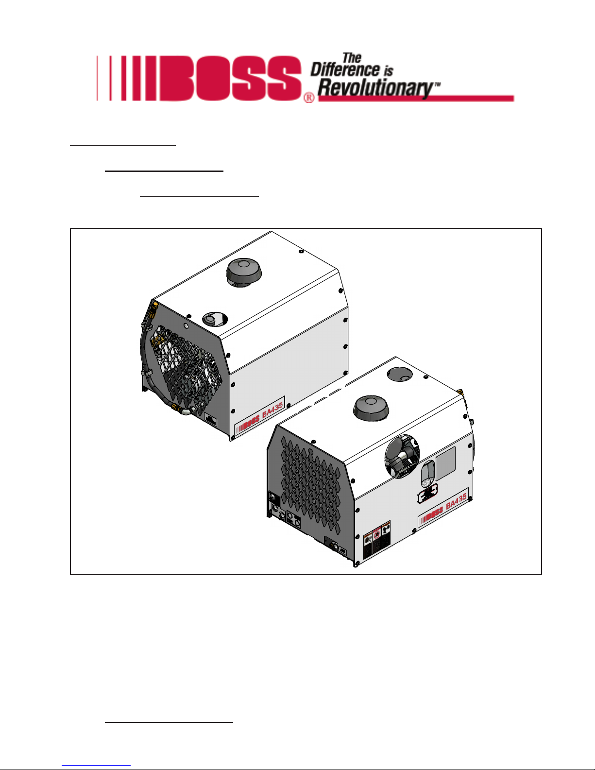
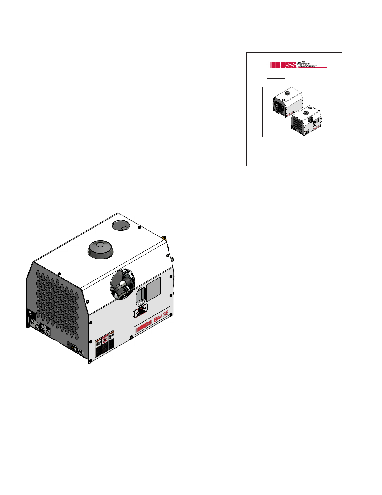
Boss BA435 Hydraulic Air Compressor
The Boss BA435 is a compact, strategically designed system. It integrates all major components on a single
frame, which is enclosed in a tough, weather-resistant canopy.
The BA435 Piston design provides output of up to 35
CFM (cubic feet of air per minute) at up to a maximum
of 150 PSI (pounds per square inch). High output at
relatively low GPM (gallons per minute) translates into
the most efficient, quiet, and reliable system in its class,
designed to handle virtually any application.
The BA435 Piston also has enhanced safety features
offering applications designed to protect your most
valuable resource - your operating crew. To prevent
overheating, a high temperature switch will shut down
the machine in the event of high discharge
temperatures.
This manual must be read carefully before using your Boss Industries Air Compressor.
Store in a safe and convenient location for future reference.
For technical support:
Phone: (800) 635-6587 (USA)
Phone: (219) 324-7776 (Outside USA)
Fax: (877) 254-4249 (USA)
service@bossair.com (email)
http://www.bossair.com (website)
309395
01/24/2012 CRH
Service and
Maintenance
User Manual Hydraulic Air Compressor
BOSS
BA435 PISTON

7309395
IMPORTANT READ BEFORE OPERATING EQUIPMENT
Remember, safety is basically common sense. While there are standard safety rules, each situation has its
own peculiarities that cannot always be covered by rules. Therefore with your experience and common
sense, you are in a position to ensure your and others safety. Lack of attention to safety can result in:
accidents, personal injury, reduction in efficiency and worst of all – Loss of Life. Watch for safety hazards
and correct them promptly.
Understanding the proper operation of this equipment is critical to its safe operation. The owner, lessor or
operator of this equipment is hereby notified and forewarned that any failure to observe the safety and
operating guidelines may result in injury and/or damage. Boss expressly disclaims responsibility or liability
for any injury or damage caused by failure to observe these specified precautions or by failure to exercise
the ordinary caution and due care required while operating or handling this equipment, even though not
expressly specified.
In addition to following these safety guidelines, the operator should follow any company specific guidelines
and procedures. Consult your immediate supervisor for specific company safety guidelines and/or proce-
dures.
The following safety symbols are used throughout the manual to draw attention to important information. If
the information is not carefully read and the instructions are not followed, severe injury, death, and/or
damage to property and equipment may occur.
Indicate[s] an imminently hazardous situation, which, if
not avoided, will result in death or serious injury.
Indicate[s] a potentially hazardous situation, which, if not
avoided, could result in death or serious injury.
Indicate[s] a potentially hazardous situation, which, if not
avoided, could result in minor or moderate injury.
Indicate[s] a potentially unsafe situation or practice,
which, if not avoided can result in property and/or
equipment damage only.
Safety

8309395
Safety
The following safety precautions are a general guide to safe operation of the equipment.
Read and understand the operations manual and all other safety
instructions before using this equipment. Failure to follow
operating instructions and/or failure to follow maintenance proce-
dures and intervals could result in personal injury, death, and/or
damage to equipment and property.
Pressurized System. Do not attempt to remove any compressor
parts without first completely relieving entire system of pressure.
Do not attempt to service any part of the equipment while in
operation. Never attempt to repair or modify any pressure vessel
or device.
System contains hot oil. The compressor system must be shut off
prior to servicing. Open the service valve to ensure complete relief
of system air pressure and stored energy. Then permit system to
cool down prior to adding compressor oil or servicing the unit.
Do not use air from this compressor for breathing or food process-
ing. Air from this compressor will cause severe injury if used for
breathing or food processing.
The compressor is designed to compress air only. Do not attempt
to compress other gases. Compression of other gases may create
a situation where an explosion or fire may occur.
Do not use flammable solvents for cleaning compressor parts as
this can cause the unit to ignite or explode during operation. Keep
combustibles out of and away from compressor inlet, and any
associated enclosures.

9309395
Safety
Never disable, override, or remove safeties, either temporarily or permanently.
Do not modify pressure switches to operate equipment at a higher pressure
than specified. When using a hose reel, the complete system must be designed
with safety valves in accordance with OSHA Regulation 1910.169.
Never leave the machine running unattended or leave a tool connected to an
air hose when not using. Relieve system of all stored air pressure after use.
Never adjust the pressure switch to a setting of greater than 150 PSI. Oper-
ating the compressor at greater than 150 PSI may result in personal injury and
property damage.
Mount the compressor in a stable location capable of supporting 180 lbs.
Slight vibration may occur during operation and the machine may move if not
securely mounted.
When using tools, maintain secure footing at all times. Do not overreach or
awkwardly use air tools.
Prior to moving vehicle to the next work site, drain the air tank. To prevent
the collection of water in the tank drain daily.
Use only Boss approved replacement parts.
10 309395
– BA435 system is to run intermittently.
– When the BA435 is installed with other hydraulic drive equipment it will require a dedicated flow line.
– If other hydraulics are required, the reservoir size should be at least 12 GAL for the BA435 plus all the other
manufacturer’s requirements.
– Mounting surface must be capable of 180 lbs. load spread over the four mounting holes.
– Cooling air intake must not see air temperatures above ambient.
– Cooling air discharge must have 10” clearance from any obstructions.
–Ambient running conditions: -20° to 100° F.
– 20° maximum operating slope.
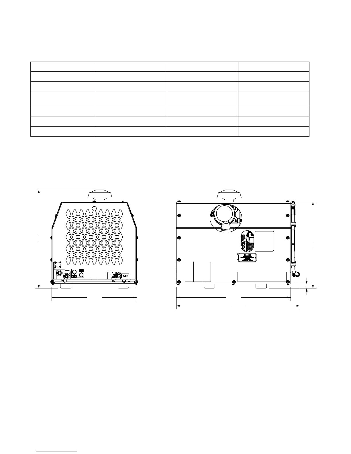
Specifications
SPECIFICATIONS SUBJECT TO CHANGE WITHOUT PRIOR NOTICE
ECRUOSREWOP ROTOMCILUARDYH DEEPSGNITAREPO .XAMMPR0041
.GIFNOCREDNILYC notsiP4V YTICAPACLIO STQ3/11
SNOISNEMID W"4/391xH"8/191xL"2/162 THGIEW .SBL081
ISP001@YREVILED MFC53 RIOVRESERCILUARDYH
*.QER MUMINIMNOLLAG21
GNILOOC RIA MPR0041@MPGLAMRON MPG3.9
RETEMAIDNAF "8/141 ISPGNITAREPOLAMRON ISP0581
ISPMUMIXAM ISP0042
* Hydraulic reservoir requirement for compressor only. Additional capacity will be needed to other hydraulic
equipment.
1.00
20.12
26.50
28.60
19.74
22.91

11 309395
Description of Components
CompressorAssembly - The Boss BA435 hydraulic drive piston compressor assembly is a positive
displacement, intermittent-flow, reciprocating unit. The piston compressor consists of a crankshaft, oil filter,
oil pump, four connecting rods, pistons, cylinders, and valve assemblies. As the crankshaft rotates, the
pistons move up and down. As they move down, a vacuum is created above the piston which allows the
reed valve to open and fill the area above the piston with air. When the pistons move back up, this air is
discharged from the compressor. Oil lubricates the bearings and cylinder walls as the crankshaft rotates,
ensuring that the system stays cool.
Hydraulic Oil Cooling Systems - The compressor cooling system consists of a hydraulic cooler mounted
on the compressor frame. Cool air is drawn through the vented end panel and flows over the compressor
surface and through the hydraulic cooler, exiting out the front vented panel .Allow for adequate clearance
(10”) for the air to exit. Also, the package location should not be subjected to air temperatures above
ambient.
Dipstick - The dipstick indicates the fluid level in the crank case. Proper level should be at the “FULL” line
on the dipstick. Check this level when the compressor is disengaged and the vehicle is parked on level
ground. Fluid level should be checked prior to each use.
Electrical System - The Boss compressor’s standard electrical system consists of:
-Hydraulic oil cooler fan assembly and relay.
-12VDC N.O. hydraulic solenoid.
-Switch relay for customer equipment interface during compressor operation.
Most air tools operating pressure range is between 90 and 125 psi.
Operating above the tools’recommended pressures will decrease the life
of the tool. Higher operating pressure can also over torque nuts and bolts
fatiguing the fastener and mating parts. Strictly adhere to tool operating
pressures and torque standards set forth by the tool manufacturer and the
specifications of the equipment that work is being performed on.
Pressure Switch - The pressure switch is a N.C. electrical switch set to open at 150 PSI and set to close
at 115 PSI. The pressure switch controls the N.O. hydraulic solenoid. If service air pressure is under 150
PSI, the pressure switch will remain in its normally closed state, keeping the N.O. hydraulic solenoid closed
and the compressor producing air. If the service valve is closed or the tool using the air is off, service line
pressure will rise to 150 PSI. This will cause the pressure switch to open and deactivate the hydraulic
solenoid. The compressor will stop making air. If the tool is turned on or the service valve is opened, the
service line pressure will drop. When the pressure falls to 115 PSI, the pressure switch will close, energiz-
ing the N.O. hydraulic solenoid forcing flow to the motor and the compressor will start producing air to
meet the demand.
Never adjust the pressure switch to a setting of greater than 150 PSI. Oper-
ating the compressor at greater than 150 PSI may result in personal injury and
property damage.

12 309395
Installation & Operation
This air compressor should be installed only by those who have been trained and delegated to do so and
who have read and understand the manual. Failure to follow the instructions, procedures, and safety
precautions in this manual may result in accidents and injuries.
Install, use, and operate this air compressor only in full compliance with all pertinent O.S.H.A., Federal,
State, and Local codes or requirements in addition to Boss and any company’s regulations.
Do not modify this compressor except with written factory approval.
ALL TRUCKS SHOULD BE ROAD TESTED PRIOR TO STARTING
INSTALLATION TO ISOLATE ANY PREVIOUS TRUCK PROBLEMS.
1. Mounting the Compressor
When mounting the compressor care should be taken to ensure that its location does not impede the
operation of other components on the vehicle. For example, if your vehicle is equipped with a crane,
you must make sure the compressor will not interfere with the swing of the crane. In addition, the
compressor should be installed in an area that permits cool ambient air to enter the air filter and the
hot air to exhaust without recirculating into the air filter. 10” of exhaust clearance is needed. The
compressor air filter is mounted on the frame. Cool ambient air is drawn in from under the frame. One last
consideration in the mounting should be the routing of hoses and electrical wires. The frame mounting holes
are shown below and the unit should be secured to the vehicle with 3/8 inch grade 8 bolts and washers.
Hardware supplied with unit, may not work in all applications. The compressor weighs 180 lbs. Ensure
that you have a sub structure to support at least that weight. Be sure to follow all National Vehicle Safety
Standards.

13 309395
2. Installing the Wiring
This unit is shipped from the factory with all necessary internal wiring installed. The only remaining
wiring necessary is the wiring needed to interface your vehicle/power source with the Boss compressor.
The unit is shipped with a 5 pin connector, they need to be connected as follows:
1. Pin “B” and Pin “E” are to be connected directly to battery positive (Pin “B” red wire) and
battery negative (Pin “E” black wire).
2. Compressor Only: for normal compressor operation, supply 12VDC inputs to Pin “A” (yellow
wire). This will activate the system and pressure the tank to 150 PSI. The system will then
unload until the tank has dropped to 110 PSI, at which point it will automatically activate. The
12VDC output signal from Pin “D” (orange wire) will be present only when the system is
compressing.
3. Pin “C” (green wire) is connected to PTO ground.
3. Connecting the Hydraulic Hoses
The hydraulic hoses to the compressor should be connected directly to the hydraulic block. The port sizes
in the blocke are -10 SAE. The pressure “P” input line should be made from a good quality high pressure
hydraulic hose 1/2” or 3/4” I.D. rated to handle the hydraulic systems on the vehicle. The return line to tank
“T” can be made from a medium pressure (min. 1000 PSI) hydraulic hose 3/4” I.D. Care should be taken
to see that the hoses are not installed with kinks or bends that inhibit flow of the hydraulic oil. Lack of flow
could result in damage to the motor and compressor. Lastly check to make sure hoses are not in contact
with sharp objects or edges that may fray, chafe or cut them over time. Secure all hoses with tie down
straps or clamps.
4. Connecting the Air Hose
The air discharge hose should be connected directly to the “AIR” port. The fitting is a 1/2” female NPT. The
air line should be made from a good quality (min. 200 PSI) hydraulic hose 1/2” or 3/4” I.D. Care should be
taken to see that the hose is not installed with kinks. When adding an air hose, ensure OSHA Regulation
1910.169 is followed.
Installation & Operation
AIR
OUT
HYDRAULIC
TANK OUT
HYDRAULIC
PRESSURE
IN

14 309395
This inspection should be done prior the compressor test.
I. Check all assemblies, clamps, fittings, hose connections, nuts, and bolts to ensure they are properly
tied and secured to the vehicle. This is a very critical area of inspection. The vehicle should not be
moved until this inspection has been completed.
II. Remove all tools, rags, and installation equipment from the area.
III. Check compressor oil level and hydraulic fluid level. Check all valves to ensure they are in correct
operating position.
IV.Apply decals to proper location. Make sure that the area is cleaned prior to applying decals. All
decals should have a professional appearance upon application.
V. Vacuum all areas that have metal or plastic shavings. Wipe all fingerprints off unit and vehicle.
Installation & Operation
5. Pre-Start-up Inspection Checks
Acompressor service valve should be located at the hose reel inlet or the customer’s air connection
port when a hose reel is not used. Typical plumbing from the machine’s air outlet port occurs in the
following order:
1. Air tank
2. OSHA valve.
3. Service valve.
4. Moisture trap/gauge/oiler combination (when used).
5. Hose reel (when used).

15 309395
V. Record all serial numbers for this installation.
A. Vehicle V.I.N.
___________________________________________________________________________
B. Hydraulic Pump Data
___________________________________________________________________________
C. Compressor Serial Number
___________________________________________________________________________
D. Boss Serial Number
___________________________________________________________________________
E. Air Tank Serial Number
___________________________________________________________________________
F. Note any special applications relating to specific installations.
___________________________________________________________________________
VI. Check all fluid levels (position the unit on a level surface so that proper amount of fluids can
be added).
A. Fuel to provide three hours of operation.
B. Hydraulic fluid levels may have to be topped off after test.
C. Compressor.
Check the compressor oil level (see lubricant section of the operator and
parts section for type of lubricant to use). 1. Add oil if needed. 2. Additional oil
may need to be added after test. 3. Top off oil level to the “FULL” line on the dipstick when
finished with the test.
D. Any other applicable fluids.
E. Transmission fluid and PTO box.
Installation & Operation

16 309395
6. Operating Procedure
I. Read the operation section in the manual carefully before proceeding onto the initial start-up.
II. Start power source and allow for warm-up.
III. Verify the compressor is disengaged.
IV.Engage hydraulic system per company policy.
V. Engage compressor.
7. Shutdown Procedure
I. Disengage compressor circuit.
II. Relieve system of stored air.
Installation & Operation
Operating Conditions
The following conditions should exist for maximum performance of the compressor. The truck should be as
close to level as possible when operating. Operation in ambient temperatures above 100°F (38°C) may
experience high temperature shutdown.
17 309395
This section contains instructions for performing the inspection, lubrication, and maintenance proce-
dures required to maintain the compressor in proper operating condition. The importance of per-
forming the maintenance described herein cannot be over emphasized.
The periodic maintenance procedures to be performed on the equipment covered by this manual are
listed on the following page. It should be understood that the intervals between inspections specified
are maximum interval. More frequent inspections should be made if the unit is operating in a dusty
environment, in high ambient temperature, or in other unusual conditions. Aplanned program of
periodic inspection and maintenance will help avoid premature failure and costly repairs. Daily
visual inspections should become a routine.
Maintenance
Recommended Spare Parts List
How To Order Parts
For Parts and/or Service Support:
Phone: (800) 635-6587 (USA)
Phone: (219) 324-7776 (Outside USA)
Local Fax: (877) 254-4249
service@bossair.com (email)
http://www.bossair.com (website)
Compressor must be shut down and completely relieved of pressure
prior to checking fluid levels. Open service valve to ensure relief of
system air pressure. Relieve all stored air pressure energy prior to
starting machine. Failure to comply with this warning will cause
damage to property and serious bodily harm.
PART NUMBER DESCRIPTION
80279 KIT, REPAIR REED VALVE
300854 ELEMENT, AIR FILTER
301267 SPIDER, CURVED JAW
302936 KIT, REPAIR HYD MOTOR SEAL
308245 LUBRICANT, 2QT BOX SYNTH

18 309395
Maintenance
Lubrication and Maintenance Chart
The LUBRICATION AND MAINTENANCE CHARTlists serviceable items on this compressor
package. The items are listed according to their frequency of maintenance, followed by those items
which need only “As Required” maintenance.
Use only Boss’ synthetic compressor oil. The use of any other oil causes excessive carbon buildup, and
may void the warranty on the compressor.
NOTE 1.
Under normal operating conditions, oil changes are required every 3 months. When operating in a dirty
environment, change the oil and air filter more frequently as your particular operating conditions dictate.
Compressor oil capacity is 1-1/3 quarts.
NOTE 2.
Cylinder head stud torque MUST be checked after the initial day of operation. The compressor must be
cold (room temperature) before re-torquing of studs. Torque studs to 240 in-lbs plus or minus 10 in-lbs.
LAVRETNIECIVRES NOITAREPOECNANETNIAM
YLIAD .dedeenfiddA.levellioesacknarckcehC.1
.reviecerriamorfnoitasnednocniarD.2
YLKEEW
.ekatniriaehttcepsnI.1
.)2ETONees(euqrotdutsdaehrednilycehtkcehC.2
.sevlavytefasreviecerehtfonoitarepoehtkcehC.3
SHTNOM3YREVE .)1ETONees(lioesacknarcehtegnahC.1
.dedeenfinaelC.noitcurtsbodnatridrofsnifreloockcehC.2
SHTNOM6YREVE .raewrofgnilpuocevirdehttcepsnI.1
.renaelcriaehtegnahC.2

19 309395
The following are general characteristics for a piston lubricant. Due to the impossibility of establishing limits
on all physical and chemical properties of lubricants which can affect their performance in the compressor
over a broad range of environmental influences, the responsibility for recommending and consistently
furnishing a suitable heavy duty lubricant must rest with the individual supplier if they choose not to use the
recommended Boss Piston lubricant. The lubricant supplier’s recommendation must, therefore, be based
upon not only the following general characteristics, but also upon his own knowledge of the suitability of the
recommended lubricant in piston air compressors operating in the particular environment involved.
Maintenance
Lubrication Recommendations
Mixing different types or brands of lubricants is not recommended
due to the possibility of a dilution of the additives or a reaction
between additives or different types.
TINU DOHTEM GNITAR
EDARGYTISOCSIVOSI 8443OSI 64
YTISOCSIVCITAMENIK 544DMTSA
)F°401(C°04TA- s/2mm 64
)F°212(C°001TA- s/2mm 7.7
)F°95(C°51TAYTISNED Lm/g 8921DMTSA 348.
)COC(TNIOPHSALF )F°(C° 29DMTSA )554(532
TNIOPRUOP )F°(C° 79DMTSA )94-(54-<
)IV(XEDNIYTISOCSIV 9092OSINID 531
SEITREPORPNOITNEVERPTSUR B-566DMTSA SSAP
YTILIBAREPESRETAW nim 1041DMTSA 01
LESSEVERUSSERPGNITATOR
TSETNOITADIXO nim 2722DMTSA 0022
TSETGNIYRRACDAOLGZF
ERULIAF
DAOL
EGATS
59-A-70-L-CEC 21>
It is important that the compressor oil be of a recommended
type and that this oil as well as the air filter element be in-
spected and replaced as started in this manual.

20 309395
Compressor Oil Fill, Level, and Drain
Before adding or changing compressor oil, make sure that the compressor is completely relieved of
pressure. Oil is added at the fill cap on a pipe on the rear of the crankcase. Adrain line is located on the
rear panel of the machine. The proper oil level is to the “FULL” line on the dipstick, when the unit is shut
down and has had time to settle. The truck must be level when checking the oil. DO NOT OVERFILL.
The oil capacity is given in “Compressor Specifications”.
Maintenance
Air Intake Filter (P/N 300854)
The air intake filter is a heavy-duty dry type high efficiency filter designed to protect the compressor
from dust and foreign objects.
Frequency of maintenance of the filter depends on dust conditions at the operating site. The filter
element must be serviced when clogged. Aclogged air filter element will reduce compressor performance
and cause premature wear of components.
Do not attempt to drain condensate, remove the oil level fill cap, or
break any connection in the air or oil system without shutting off
the compressor and relieve the system of all stored air pressure.
Due to environmental factors, the useful life of all “extended life”
lubricants may be shorter than quoted by the lubricant supplier. Boss
encourages the user to closely monitor the lubricant condition and to
participate in an oil analysis program with the supplier.
No lubricant, however good and/or expensive, can replace proper
maintenance and attention. Select and use it wisely.
Table of contents
Other Boss Industries Air Compressor manuals


Popular Air Compressor manuals by other brands

Kärcher
Kärcher BOGE CM9 Series operating instructions

Streetwize
Streetwize SWAC11 instruction manual

California Air Tools
California Air Tools 12V1P10S owner's manual

NITEO TOOLS
NITEO TOOLS NE-8622 Original user manual

Trane
Trane R410a installation guide

Bostitch
Bostitch RC10SQ-M Safety and operating instructions manual

VIAIR
VIAIR Exreme Series manual

Sealey
Sealey RE229.V4 quick start guide

Profi-AirBrush
Profi-AirBrush UNIVERSAL II-C operating instructions

Craftsman
Craftsman evolv 15206 Operator's manual

Campbell Hausfeld
Campbell Hausfeld WL6000 Series operating instructions

Sealey
Sealey Power Products SAC00015 instructions


