BOSSCO BPTEB260 User manual

34 Yarraman Place
Virginia, QLD, 4014
Ph: 03 8726 1471
Email: [email protected]
Web: www.bosspowertools.com.au
BPTEB260
INSTRUCTION MANUAL
PETROL
POWER BLOWER 26cc
WARNING!
Read all safety warnings and all instructions and retain this manual for future reference.
Failure to follow the warnings and instructions may result in fire and/or serious injury.

INTRODUCTION
compromise to quality, comfort, safety or durability.
BBT-260 high performance engines represent the leading edge for 2
一
cycle engine technology, delivering exceptionally
high power at remarkably low displacement and weight. As a professional owner/operator you will soon discover why
BBT-260 is simply in a class by itself!
IMPORTANT!
The information contained in this manual describes machines available at the time of production. While every attempt has
between your machine and what is described here. We reserve the right to make changes in production without prior
notice and without obligation to make alterations to machines previously manufactured. Before using this product consult
local regulations concerning noise restrictions and hours of operation.
CONTENTS
Attention Statements ................................................................................................................. 3
NOMENCLATURE ...................................................................................................................... 4
Specifications
.............................................................................................................................
5
Assembling the Blower ............................................................................................................. 5
Mixing Fuel .................................................................................................................................. 6
Filling the Fuel Tank
..................................................................................................................
11
Starting the Blower ................................................................................................................... 12
Adjusting Engine Speed........................................................................................................... 13
Using the Blower ...................................................................................................................... 15
Routine Maintenances
.............................................................................................................
16
Spark Arrestor Maintenance .................................................................................................... 19
Storage ...................................................................................................................................... 20
Troubleshooting
.......................................................................................................................
21
A
CAUTION!
This engine blower is equipped
with a spark-arresting muffler. Never
operate this machine without both the
muffler and spark arrestor installed and
properly functioning!
been made to give you the very latest information about your BPTEB260 engine blower, there may be some differences
BPTEB260 engine blowers have been designed and built to deliver superior performance and reliability without
BPTEB260

ATTENTION STATEMENTS
This manual contains special "attention statements " surrounded by boxes and preceded by the
triangular Attentions Symbol.
Additional attention statements that are not preceded by the Attention Symbol are:
IMPORTANT!
A statement preceded by the word "IMPORTANT" is one that possesses special significance。
NOTE:
A statement preceded by the word“NOTE”contains information that is handy to know
and may make your job easier.
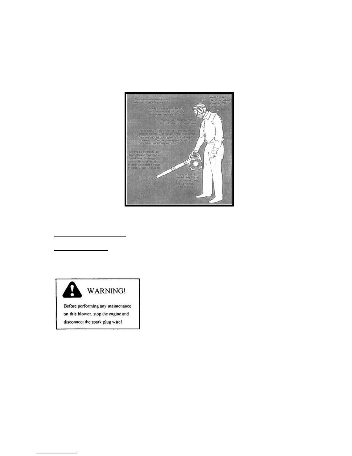
Read and follow this manual. Failure to do so could result in serious injury.
Wear eye and hearing protection at all times during the operation of this
machine.
Do not operate this machine if you are tired, ill or under the influences of
alcohol, drugs, or medicine.

IMPORTANT!
The operational procedures described in this manual are intended to help you get the most
from your machine and also to protect you and others from harm. These procedures are
general guidelines ONLY and are not intended to replace any safety rules/laws that may be in
force in your area.
WARNING !
Do not make unauthorized
Modifications to this
machine.
NOMENCLATURE
If you have any questions regarding your BPTEB260 engine blower, or if you do not understand
something in this manual, please contact your dealer to assist you.

SPECIFICATIONS
Model
Dimensions (L X W X H)..... 400 X 260 x 360 mm
Engine Type 2 cycle air, Petrol Engine vertical cylinder
Bore & Stroke 34 X 28
Displacement 26cc
Fuel Fuel/oil mixture (25-30) •1
Carburetor Diaphragm-type with primer pump
Ignition All transistor electronic ignition system
Starting Recoil starter
Stopping Grounding (toggle switch)
Fuel Tank Capacity 0.65 1itres
Exhaust system Low dB; spark-arrestor muffler
Air Quality Type Semi-wet
Weight (dry: with blower tubes) 4.2kg
ASSEMBLING THE BLOWER
BPTEB260

Place the blower upright on the ground or on a sturdy work surface.
1. Grasp the straight tube as shown, and push the tube over the blower discharge port
and locking pins.
2. Lock the straight tube to the blower discharge by rotating the tube as shown.
3. Grasp the nozzle tube with the label“TOP”,positioned as shown, and then push the
nozzle over the straight tube and locking pins。
4. Lock the nozzle tube to the straight tube by rotating the nozzle tube as shown.
IMPORTANT!
Blower tube installation affects both blower
balance and performance! The tube and nozzle
are correctly installed when the label “TOP”is
visible to the operator during normal operation.
MIXING FUEL
Fuel Requirements
Use only fresh,clean fuel
Use only fuel with an octane rating of
90 or higher
Mix all fuels with premium 2-cycle
Engine oil at a gasoline/oil ratio of
(25 - 30) :1
WARNING!
balance and performance! The tube
and nozzle are correctly installed when
the label “TOP”is visible to the operator
during
Danger from rotating impeller 丨Stop
the engine before installing or removing
the blower tubes! Never perform any
maintenance or assembly procedures
on this machine while the engine is
running!
WARNING!
Danger of fire! Never transfer or store
fuels in the presence of combustible
materials I Before starting the engine,
always move the blower to a clear area
at least 10-feet (3*metres) away from
fuels and other combustible materials!
CAUTION!
Never attempt to mix fuel in the blower fuel tank! Always mix all fuels in a clean, approved
container!
Some Fuel contains alcohol as an oxygenate! Oxygenated fuels may cause increased
engine operating temperatures! Under certain conditions ,alcohol-based fuels may also
reduce the lubricating qualities of some mixing oils! Never use any fuel containing more
than 10% alcohol by volume! When an oxygenated fuel must be used, fuel containing an
ether-based oxygenate such as MTBE is preferred over alcohol!
Whenever possible, use 2-cycle engine oil or equivalent oil mixed at a 25-30:1 ratio. Be
aware that generic oils and some outboard mixing oils may not be intended for use in high
performance air cooled 2-cycle engines, and should never be used in your engine blower.


List of Parts of Attached Figure 1
SER.N
O
PART NO.
PART NAME
QTY.
SER.N
O
PART NO.
PART NAME
QTY
.
1
GB/T70.1M5X50
SCREW
2
34
1E34F.7-2
CRANK CASE
CASKET
1
2
GB/T93 5
WASHER
2
35
1E40F-3Z.3-1
KEY
1
3
GB/T96 5
WASHER
2
36
1E34F.6.1
CRANK SHAFT
COMP.
1
4
1E34F.5-2
PLUG CAP
1
37
1E34F.7-3
CRANKCASE
1
5
1E40F-3A.8-2
CLICK SPRING
1
38
1E34F.8.1
STARTER
PULLEY
1
6
RCJ6Y(CHAMPIO
N)
PLUG
1
39
1E34F.8-2
STARTER PULL
SPRING
1
7
1E34FB-5
MUFFLER
1
40
1E34F.8-1
STARTER PULL
1
8
GB/T9074.4
M5X16
SCREW
1
41
1E34F-2
CYLINDER
WASHER
2
9
42
1E34FB-3
SLAD
1
10
1E34FB-4
SLAD
1
43
1E34FB.2
INLET
MANIFOLD
1
11
GB/T70.1M5X20
SCREW
2
44
GB/T9074.4
M5X25
SCREW
2
12
GB/T93 5
WASHER
2
45
1E34FB.1
PULL ROD
1
13
GB/T848 5
WASHER
2
46
1E34FB-8
PULL ROD
COVER
1
14
1E34F.5-1
RUBBER PLUG
1
47
1E34FB-2
SEALING
WASHER
1
15
GB/T9074.4
M4X20
SCREW
2
48
1E34FB-1
INLET
MANIFOLD
1
16
MAGNETO
STATOR
1
49
1E34F-1
SEALING
WASHER
1
17
1E32FL-6
HEAT
INSULATION PAD
2
50
WYJ244
CARBURETOR
1
18
1E34FB-5
CYLINDER
1
51
1E34FB.6.2
CLEANER
INSIDE COVER
1
19
1E34FB-5
CTLIMDER
WASHER
1
52
1E34FB-6
CHOKER
1
20
1E34F-9
PISTON RING
2
53
1E34FB-7
BAFFLE
1
21
1E34F.6-6
PISTON
1
54
GB/T9074.4
M5X55
SCREW
2
22
1E34F.6-3
PISTON PIN
1
55
1E34FB.6.1
CLEANER
ELEMENT
1
23
1E34F.6-2
PISTON PIN
CIRCLET
2
56
1E34FB.6-1
CLEANER
OUTSIDE
COVER
1
24
1E34F.6-1
STOP RING
2
57
CG420.1.6.3
SCREW
1
25
1E34F.6-4
NEEDLE
BEARING
1
58
GB/T9074.6
M5X10
SCREW
1
26
GB/T6171 M8X1
NUT
1
59
1E34F.11-1
RECOIL SPRING
1
27
GB/T97.1 8
WASHER
1
60
1E34F.11-3
ROPE
1
28
MAGNET ROTOR
1
61
1E36F.1-5
CASKET
1
29
GB/T9074.4
M5X25
SCREW
4
62
1E36F.1-1
STARTER
HANDLE
1
30
1E36F.2
OIL SEAL
2
63
GB/T9074.4
M4X10
SCREW
4
31
1E34F.7-1
1
64
1E34F.11-2
STARTER ROPE
REEL
1
32
GB/T 119 B3X10
ANNUL
2
65
1E34F.11G.1
RECOIL
STARTER BOOT
1
33
GB/T276 6001/P5
BALL BEARING
2
66
1E34F.11G
STARTER
1


List of Parts of Attached Figure 2
Ser.
NO.
Part NO
Part Name
Qty
Ser.No
.
Part No
Part Name
Qty
1
GB/T818 M5X16
SCREW
16
1E32FL.6.2-4
CHINA
1
2
GB/T95 5
WASHER
24
19
BBT-415.4.1.1-
1
AIRVALVE
1
3
BBT-260.1-2
NET COVER
1
20
1E32FL.6.2-3
ENDCOVER
1
4
BBT-260.1.2
VOLUTE CASE
1
21
CG420.1.3.1-2
SEALING
WASHER
1
5
BBT-260-4
HANDLE
COVER
1
22
1E32FL.6.2-2
LID
1
6
BBT-260.3
STOP SWITCH
1
23
1E32FL.6.2-1
FUEL TANK
LID
1
7
BBT-260.1.1
VOLUTE CASE
1
24
BBT-260-10
SUPPORT
2
8
BBT260-8
PIPE
1
25
BBT-260-14
SUPPORT
2
9
BBT260-7
PIPE
1
26
1E34F.9.2-3
FILTER
1
10
BBT260.2
STOP LINE
1
27
1E34F.9.2-2
FUEL TUBE
1
11
GB/T6172.1 M8
NUT
1
28
1E36F.8.1-1
PLUG
1
12
1E34F.5-1
RUBBER PLUG
1
29
1E34F.9.2-1
TUBE
1
13
BBT-260-2
HANDLE
1
30
GB/T70.1
M5X30
SCREW
4
14
BBT-260-3
HANDLE
COVER
1
31
BBT260.1-1
IMPELLER
1
15
BBT-260-12
SUPPORT
1
32
GB/T70.1
M5X20
SCREW
4
16
BBT-260-1
PROTECTION
1
33
BBT-260-9
SWITCH
1
17
BBT-260.5-1
FUEL TANK
1
34
BBT-260.4
FUEL
THROTTLE
1

FILLING THE FUEL TANK
IMPORTANT:
Mix only enough fuel for your immediate needs! If fuel must be stored longer than 30 days,
it should first be treated with a stabiliser or equivalent product.
WARNING:
DANGER OF FIRE AND BURN INJURY!!
Always use extreme care when handling fuel! Fuel is highly flammable!
Never operate this blower if fuel system components are damaged or leaking;
Never attempt to refuel the engine while it is running!
Never attempt to refuel a hot engine! Always allow the blower engine to cool before
fueling;
Never smoke or light any fires near the blower or fuels;
Always transport and store fuels in an approved container;
Never place flammable material close to the engine muffler;
Never operate the blower without a properly functioning muffler and spark arrestor
installed;
Never operate the blower unless it is properly assembled and in good working condition!
Find a sturdy work surface and wipe any debris from around the fuel cap;
Remove the fuel cap;
Fill the tank with clean, fresh fuel;
Replace the cap and wipe away any spilled fuel before starting the blower.

STARTING THE BLOWER
IMPORTANT
An “ON-OFF” switch located on the left of
the blower handle grip controls the engine
ignition.
Starting Procedure:
1. Prime the fuel system by repeatedly
depressing the fuel primer bulb until
no air bubbles are visible in the fuel
discharge line.
2. Cold Engine Only. Choke the engine
by pulling the choke control to the
fully extended position (choke is
closed).
3. Place the blower on the ground, hold
the blower handle firmly with your right
hand.
4. Pull the starter cord slowly until you feel the starter engine, then…
5. ..start the blower by pulling the starter cord upward rapidly
If necessary, repeat step 5 two or three times until the engine starts.

WHEN THE ENGINE STARTS
IMPORTANT!!
For maximum blower performance and operating life, allow the engine to warm before use.
1. Run the engine at idle speed until operating temperature is reached (2 to 3 minutes)
2. As the engine warms open the choke gradually by slowly pushing the choke control in
to the fully retracted position.
3. The blower should now be ready for use.
IF THE ENGINE DOES NOT START
Repeat the appropriate starting procedures for ‘hot’ or ‘cold’ engine. If the engine still will not
start, follow the ‘Starting a Flooded Engine procedure (below).
STARTING A FLOODED ENGINE
1. Disconnect the spark plug lead, use the
spark plug wrench to remove the plug in
a counterclockwise direction.
2. If the spark plug is fouled or is soaked
with fuel, clean or replace the plug as
required.
3. Clear excess fuel from the combustion
chamber by cranking the engine several
times while the spark plug is removed.
4. Install the spark plug and firmly tighten
it with the spark plug wrench. If a
torque wrench is available, torque the
spark plug to 148-165 inch-pounds.
Reconnect the spark plug lead.
5. Repeat the starting procedures for
‘warm engine’;
6. If the engine still fails to fire or start,
refer to the troubleshooting flowchart
at the end of this manual.
Use low throttle settings when clearing lightweight materials from around lawns or
shrubbery;
Use medium to higher throttle settings to move lightweight grass or leaves from parking
lots or walkways. Use full throttle when moving heavy loads such as dirt or snow.
IMPORTANT!
Blower noise increases at higher throttle settings! Always use the lowest throttle setting
required to get the job done!
.
ROUTINE MAINTENANCE
Daily Maintenance:
Remove dirt and debris from the blower exterior;
Inspect the engine, tank and hoses for possible fuel leaks and repair as necessary;
Inspect the engine cooling fins for accumulation of dirt or debris and clean as necessary.

CAUTION:
Dirty or damaged cooling system components may allow the engine to overheat, possibly
causing serious engine damage!!
CAUTION:
Operating the blower with loose, missing, or damaged components could allow the engine to
over speed possibly causing serious engine damage!
Inspect the entire blower for damage, loose or missing components or fastenings and repair as
necessary.
EVERY 10 HOURS (More frequently in dusty conditions)
1. Loosen the air cleaner cover retaining
screw and remove the cover and filter
element;
2. Inspect the element. If the element is
distorted or damaged, replace it with a
new one.
3. Wash the element in clean fuel and
squeeze or blow dry. Wash the air
cleaner cover in clean fuel and wipe or
blow dry;
4. Install the element and cover and then
tighten the cover retaining screw.

EVERY 10 TO 15 HOURS:
Spark Plug (turn
Counterclockwise
1. Use the spark plug wrench to
remove the spark plug (turn
counter-clockwise to
remove);
2. Clean and adjust the spark
Plug gap to 0.6 – 0.7 mm.
Replace any damaged or
visibly worn plug with a
champion RCJ6Y or equivalent;
3. Install the spark plug finger-
tight in the cylinder head the
tighten it firmly with the
spark plug wrench. If a
torque wrench is available,
torque the spark plug to 148-
165 inch pounds.
CAUTION!
Never allow dirt or debris to enter the die cylinder bore!
Before removing the spark plug, thoroughly clean the spark plug and cylinder head
area!
Allow the engine to cool before servicing the spark plug!
Do not complete cylinder tightening or loosening of the spark plug while the engine is hot!
Incorrect spark plug installation can result in serious engine damage!

EVERY 50 HOURS:
(More frequently if you note reduced performance)
INSPECTION: inspect the entire blower and/or
missing tubes for damage, including components
and repair as necessary.
SPARK PLUG: Replace the spark plug with a
champion RCJ6Y gapped to 0.6-0.7mm;
FUEL FILTER: Use a wire hook to extract the fuel
filter from inside the fuel tank, and then remove and
wash the filter element in clean fuel. Before re
installing the filter, inspect the condition of the fuel
line. If damage or deterioration is noted, the blower
should be removed from service until it can be
inspected by a trained service technician.
COOLING
SYSTEM: Remove the engine cover (as described
under “Spark Arrestor”) and use a wood or plastic
scraper and soft brush to remove dirt and debris from the cylinder fins and crankcase.

SPARK ARRESTOR MAINTENANCE:
Hard starting or a gradual loss of performance can be caused by carbon deposits lodged in the
spark ancestor screen. For maximum performance, the spark arrestor screen should be
periodically cleaned as follows:

1. Remove the spark plug;
2. Remove three self-tapping screws and two machine screws from the engine cover and
then gently move the engine cover aside;
3. Remove the three spark arrestor retaining screws, then remove the spark arrestor cover,
screen, gasket and chamber;
4. Use a plastic scraper or wire brush to remove carbon deposits from the screen,
chamber and cover;
5. Inspect the screen carefully and replace any screen that has been performed, distorted
or is otherwise unserviceable;
6. Install the chamber, screen, gasket and cover in the reverse order of disassembly and
then install and securely tighten the three cover retaining screws;
7. Install the engine cover and verify that the fuel line connections are still tightly in place;
8. Install the engine cover retaining screws in the reverse order of removal and tighten
securely;
9. Install and tighten the spark plug, and reconnect the spark plug wire;
STORAGE: (30
days or longer):
CLEANING: Thoroughly the blower exterior;
INSPECTION: Inspect the entire blower and tubes for damage, including loose or missing
components and repair as necessary;
FUEL: Drain the fuel tank and then clear the carburetor and lines by running the blower until it
stops from lack of fuel;
LUBRICATION: Remove the spark plug and then pour approximately ¼ oz of oil into the
cylinder through the spark plug hole. Before reinstalling the spark plug, pull the recoil starter 2
or 3 times to distribute the oil over the cylinder walls;
AIR CLEANER: Remove, clean and reinstall the filter element as described under ‘daily’;
STORAGE: Store the blower in a clean, dry, dust-free environment.

PROBLEM SOLVING
Problem
Possible Cause
Remedy
Poor acceleration
Clogged air cleaner element
Clean the element
Clogged fuel filter
Replace fuel filter as required
Carburetor mixture too lean
Return blower to the dealer
Idle speed set too low
Adjust: (2800-3000)rpm
Engine stops abruptly
Fuel tank empty
Refuel
Clogged fuel filter
Clean or replace the fuel
filter as required
Water in the fuel
Drain, replace with clean fuel
Shorted spark plug or loose
terminal
Clean and replace the spark
plug and tighten the terminal
Ignition failure
Return blower to the dealer
Piston seizure
Return blower to the dealer
Engine difficult to shut off
Ground (stop)wire is
disconnected, or switch is
defective
Test and replace as required.
Overheating due to incorrect
spark plug
Correct Plug: Champion
RCY6J
Overheated engine
Idle engine until cool
Warped or damaged blower
fan
Inspect and replace fan as
required
Internal engine damage
Return blower to dealer
Table of contents
Other BOSSCO Blower manuals


