BOSSCO EcoMAXX EM-NRV Series Owner's manual

N A S M
EMAXX® N R V (EM-NRV)
- S E - V

Page 2
NRV NA Sup. Manual 2020 - Second Edition - Version 0020
Print date: 6/26/2020
T C
S M I..................................................................................................
S..........................................................................................................................................................
W...................................................................................................................................................
I............................................................................................................................................
NFPAC.....................................................................................................................................
EMAXX® NRV S (EM-NRVØ)...................................................................................
N R V (NRV) D..................................................................................................
N R V (NRV) D..................................................................................................
F C-F D....................................................................................................
EMAXX® I P S (O-EM-NRV-CP).................................................
R T EMAXX® EM-NRV....................................................................................................
NRV S P A I.........................................................................
”+ A I (P S).........................................................................................
M M B (O-EM-NRV-MS)..............................................................
M M NRV......................................................................................
D L S M F (O-EM-NRV-DLS)..............................................
M D L S EMAXX NRV...............................................................
D L S -R I H.........................................................
G W S EMAXX® I P..........................................
W M EMAXX® I P................................................
W D L S EMAXX® I P......................................
G W S CP.....................................................................................
W D L S CP.................................................................................
W M ......................................................................................................
S C.........................................................................................................
B D L S I P CP...........................
EMAXX® NRV S/R P...................................................................................
EMAXX® NRV C C (A S)....................................................................
EMAXX® NRV R P S ” +..............................................................
CI...........................................................................................................................

Page 3
NRV NA Sup. Manual 2020 - Second Edition - Version 0020
Print date: 6/26/2020
S M I
is manual is a supplement to the Aircom installation, use and maintenance manual for no return valves. it has
been compiled by Boss Products, LLC® for the North America market. e installer and end user must be famil-
iar with both the Aircom Manual and the Boss Products suppliment.
W
1. Boss Products, LLC® warrants to the Buyer that the material sold to Buyer will be free from manufacturing
defects at the time of shipping of such material to the job site.
2. Boss Products, LLC® further warrants to the Buyer that the workmanship and material supplied to the Buy-
er will be free from defects under proper usage for a period of 12 months from the shipping date so long as
Buyer can demonstrate (i) that such material was installed in accordance with the National Electrical Code,
NFPA guidelines, and local codes and ordinances, and (ii) that Buyer has property maintained such material
as per the maintenance requirements related to such material. e warranty provided under this Section 2,
shall become null and void if Buyer fails to prove proper installation and maintenance of materials provided
by Boss Products, LLC®.
3. e Buyer shall be responsible for remedies to problems with material and services not provided by Boss
Products, LLC®.
4. Boss Products, LLC®, at their sole discretion, will repair or replace defective material or workmanship orig-
inally supplied by them. Said defective material or workmanship shall be returned to Boss Products, LLC®
freight prepaid. Repaired or replaced materials will be returned to the customer freight prepaid.
T , -
,
. B P, LLC® , , ,
, .
S
E
,
A .
A .
A PPE
F NFPA E
A NFPA C
.
W
D .
R A M.
I
:
A , L, NEC, NFPA / G.

Page 4
NRV NA Sup. Manual 2020 - Second Edition - Version 0020
Print date: 6/26/2020
I
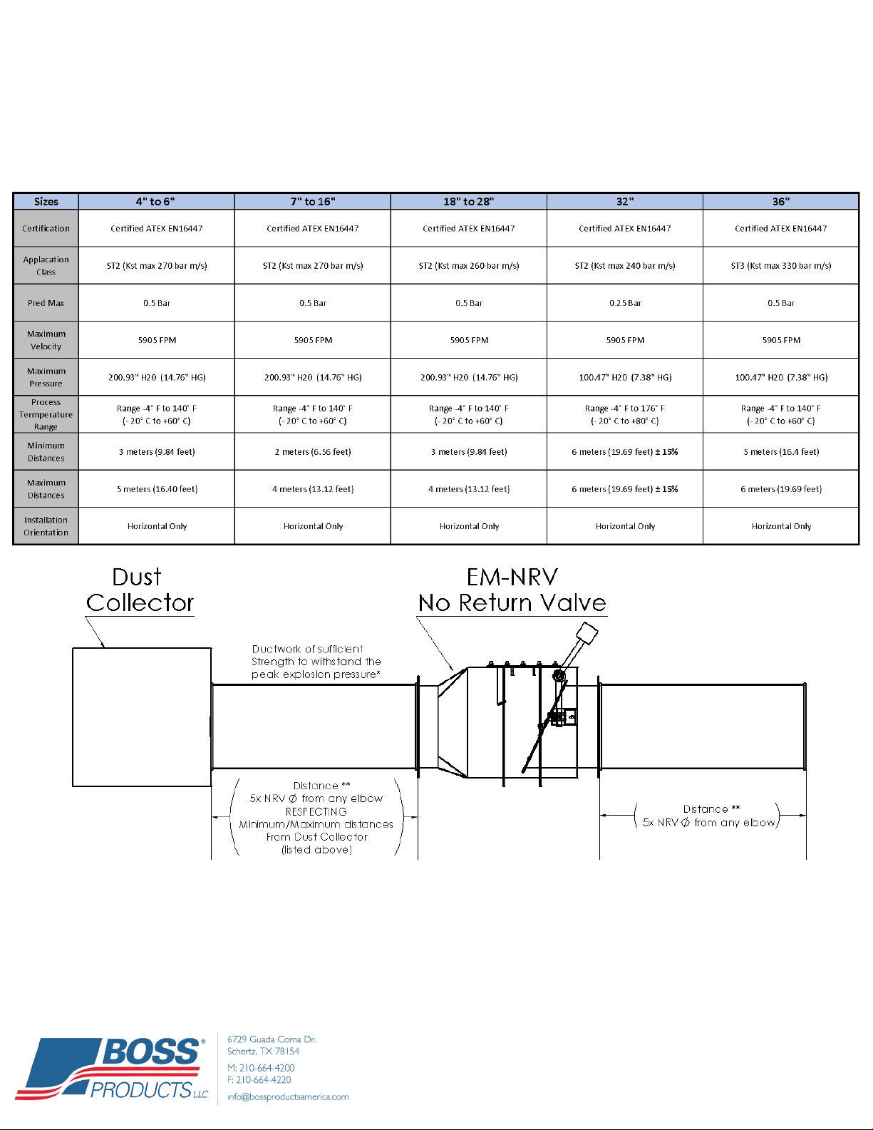
ank you for purchasing the EcoMAXX® No Return Valve (EM-NRV). e EM-NRV is an Explosion Isolation
Device specically designed to prevent deagration propagation between connected equipment. e EM-NRV is
ATEX certied and NFPA 69 compliant.
R I NFPA C:
• O-EM-NRV-CP03, Intrinsically Safe Control Panel
• O-EM-NRV-MS, Microswitch
• O-EM-NRV-DLS, Dust Level Sensor
C P:
• EM-HSAG line of High Speed Abort Gates
• EM-FBS line of Firebreak Shutters
• EM-VQ/VD/VL line of Explosion Vents
• EM-FCS Spark Detection and Extinguishment Systems
• EM-IMS line of Dust Monitoring (Emissions) Systems
• ECOBOSS Line of Energy Management Control Systems
NFPA C
NFPA – S F C D -
E
• 9.7.4 – Equipment Isolation
o 9.7.4.1* – Where an explosion hazard exists, isolation devices shall be provided to prevent deagration
propagation between connected equipment in accordance with NFPA 69.
o 9.7.4.3 – Isolation of Upstream Work Areas. Where a dust explosion hazard exists, isolation devices
shall be provided to prevent deagration propagation from equipment through upstream ductwork to the
work areas in accordance with NFPA 69.
NFPA 69 – S E P S - E
C - D C P I
o 12.2.3 F A F V
e EM-NRV meets all requirements of this section when installed with all options and conveying ductwork per
12.2.3.4.6
K P
• 12.2.3.4.2 Requires a locking mechanism which is provided standard.
• 12.2.3.4.3 Requires an Inspection door which is provided standard.
• 12.2.3.4.4 Requires an immediate, automatic shutdown of the protected process. Accomplished with O-EM-
NRV-MS Microswitch which is an available option that mounts on the NRV locking mechanism and sends a
signal upon an event.
• 12.2.3.4.5 and 12.2.3.4.5.1 requires a continuous signal to ensure valve operation is not compromised by the
accumulation of a dust layer on the bottom interior of the valve and requires an immediate, automatic and
orderly shutdown of the protected process. Accomplished with O-EM-NRV-DLS capacitive style Dust Level
Sensor (DLS) which sends a signal when 0.15”-0.20” of dust has accumulated. e DLS is located in the air-
stream and requires an intrinsically safe barrier.
• 12.2.3.5 Requires System Certication by a recognized testing organization. A.10.4.2.1 allows for European
CEN ATEX certication being acceptable.
Page 5
NRV NA Sup. Manual 2020 - Second Edition - Version 0020
Print date: 6/26/2020
EMAXX® NRV S (EM-NRVØ)
S F (A S)
Heavy Duty Welded Steel Construction * Epoxy Powder Coated Safety Red Finish
Flanged Inlet and Outlet with Co-Flanges * Grounding Lugs * Locking Mechanism(s)
ATEX Certication
NFPA 69-2019 (A.12.2.3.4.6) STATES: e minimum design pressure for the ductwork is typically 2 x Pred
because the pressure wave reects o the closed valve. Depending on the distance between the ap valve and the
enclosure, pressure piling could further increase the expected peak pressure.
** See Minimum/Maximum Distance Specications
T NRV ,
NFPA .
Page 6
NRV NA Sup. Manual 2020 - Second Edition - Version 0020
Print date: 6/26/2020
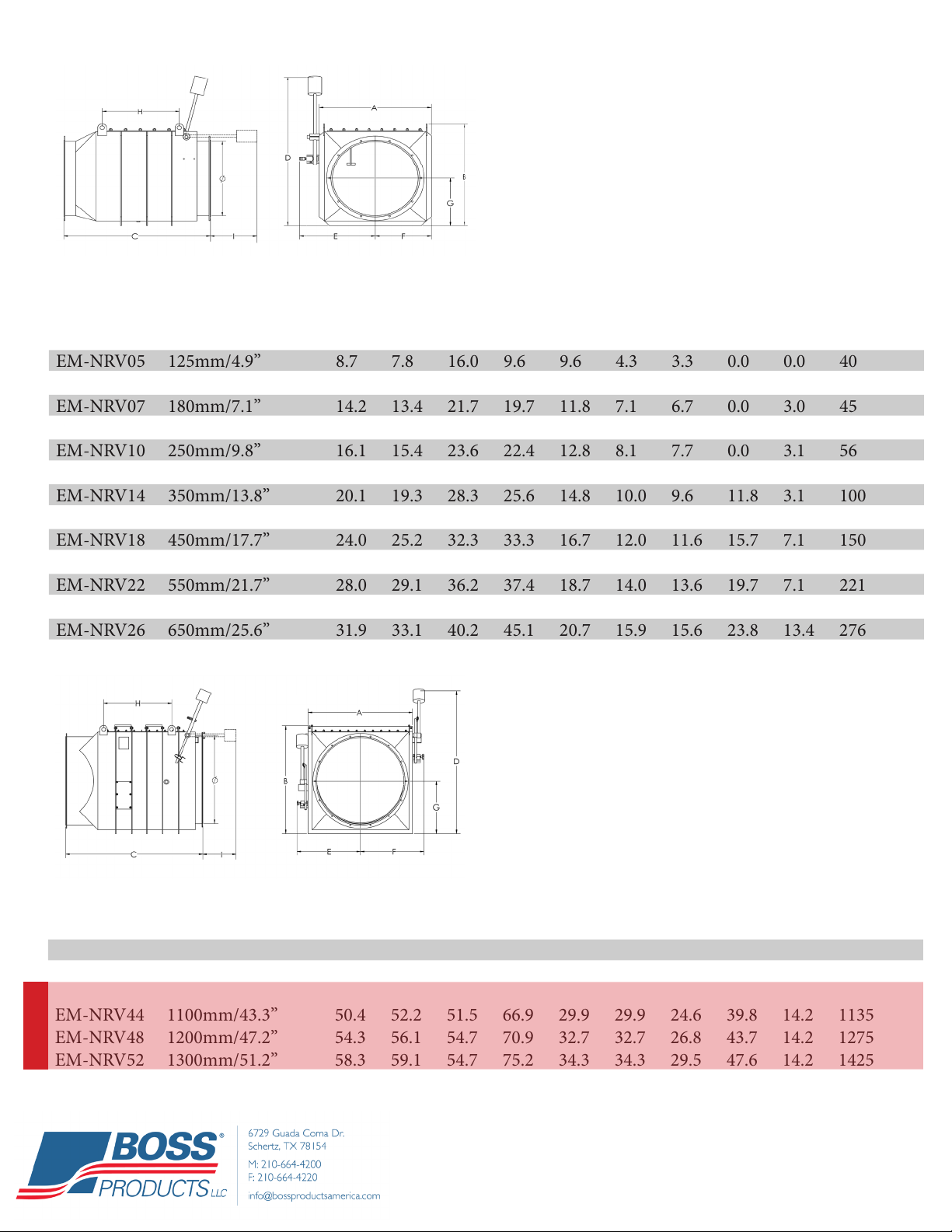
Model # Ø A B C D E F G H I LBS
EM-NRV04 100mm/3.9” 7.7 6.8 15.0 8.7 9.1 3.8 3.0 0.0 0.0 40
EM-NRV05 125mm/4.9” 8.7 7.8 16.0 9.6 9.6 4.3 3.3 0.0 0.0 40
EM-NRV06 160mm/6.3” 14.2 13.4 21.7 17.7 11.8 7.1 6.7 0.0 3.0 45
EM-NRV07 180mm/7.1” 14.2 13.4 21.7 19.7 11.8 7.1 6.7 0.0 3.0 45
EM-NRV08 200mm/7.9” 14.2 13.4 21.7 19.7 11.8 7.1 6.7 0.0 3.0 45
EM-NRV10 250mm/9.8” 16.1 15.4 23.6 22.4 12.8 8.1 7.7 0.0 3.1 56
EM-NRV12 300mm/11.8” 18.1 17.3 26.4 23.6 13.8 9.1 8.7 0.0 3.1 84
EM-NRV14 350mm/13.8” 20.1 19.3 28.3 25.6 14.8 10.0 9.6 11.8 3.1 100
EM-NRV16 400mm/15.7” 22.0 23.2 30.3 29.5 15.7 11.0 11.2 13.5 5.1 120
EM-NRV18 450mm/17.7” 24.0 25.2 32.3 33.3 16.7 12.0 11.6 15.7 7.1 150
EM-NRV20 500mm/19.7” 26.0 27.2 34.3 38.8 17.7 13.0 12.6 18.1 10.6 177
EM-NRV22 550mm/21.7” 28.0 29.1 36.2 37.4 18.7 14.0 13.6 19.7 7.1 221
EM-NRV24 600mm/23.6” 29.9 31.1 38.2 41.1 19.7 15.0 14.6 21.7 11.4 254
EM-NRV26 650mm/25.6” 31.9 33.1 40.2 45.1 20.7 15.9 15.6 23.8 13.4 276
EM-NRV28 700mm/27.6” 33.9 35.0 42.1 47.0 21.7 16.9 16.5 25.6 11.0 298
Model # Ø A B C D E F G H I LBS
EM-NRV32 800mm/31.5” 38.6 40.4 52.5 56.5 26.0 26.0 18.9 28.1 14.2 728
EM-NRV36 900mm/35.4” 42.5 44.3 44.7 60.4 28.0 28.0 20.9 28.1 14.2 860
RM-NRV40 1000mm/39.4” 46.5 48.6 48.2 64.4 29.9 29.9 22.8 35.8 14.2 1000
EM-NRV44 1100mm/43.3” 50.4 52.2 51.5 66.9 29.9 29.9 24.6 39.8 14.2 1135
EM-NRV48 1200mm/47.2” 54.3 56.1 54.7 70.9 32.7 32.7 26.8 43.7 14.2 1275
EM-NRV52 1300mm/51.2” 58.3 59.1 54.7 75.2 34.3 34.3 29.5 47.6 14.2 1425
(SIZES 4” - 16”)
RATED FOR:
Class ST 2 Applications
Kst max 270 bar m/s
Pred 0.50 bar
Certication EN 16447
(SIZE 36”)
RATED FOR:
Class ST 3 Applications
Kst max 330 bar m/s
Pred 0.5 bar
Certication EN 16447
(SIZE 32”)
RATED FOR:
Class ST 2 Applications
Kst max 240 bar m/s
Pred 0.25 bar
Certication EN 16447
*NOTE: Co-anges provided to slip over imperial sized ductwork.
*NOTE: Co-anges provided to slip over imperial sized ductwork.
N
R
N R V (NRV) D
N R V (NRV) D
(SIZES 18” - 28”)
RATED FOR:
Class ST 2 Applications
Kst max 260 bar m/s
Pred 0.50 bar
Certication EN 16447

Page 7
NRV NA Sup. Manual 2020 - Second Edition - Version 0020
Print date: 6/26/2020
• I.D. 1 Dimensions are the inner
diameter dimensions of the anges
installed on EM-NRV
• I.D. 2 Dimensions are the inner di-
ameter dimensions of the co-anges
provided with EM-NRV
F C-F D
Model # I.D. 1 I.D. 2 B.C. O.D. Holes ickness
EB-FL04 4.01” 4.06” 5.20” 6.42” 4 @ 0.4” 0.16”
EB-FL05 5.00” 5.06” 6.18” 7.42” 4 @ 0.4” 0.16”
EB-FL06 6.37” 6.09” 7.6” 8.82” 6 @ 0.4” 0.16”
EB-FL07 7.16” 7.125” 8.35” 9.49” 6 @ 0.4” 0.16”
EB-FL08 7.95” 8.125” 9.17” 10.48” 6 @ 0.4” 0.16”
EB-FL10 9.92” 10.125” 11.14” 12.48” 6 @ 0.4” 0.16”
EB-FL12 11.90” 12.125” 13.35” 14.89” 8 @ 0.4” 0.20”
EB-FL14 13.85” 14.125” 15.28” 16.88” 8 @ 0.4” 0.20”
EB-FL16 15.78” 16.125” 17.24” 18.88” 8 @ 0.4” 0.20”
EB-FL18 17.75” 18.125” 19.21” 20.88” 8 @ 0.4” 0.20”
EB-FL20 19.72” 20.125” 21.18” 22.88” 12 @ 0.4” 0.20”
EB-FL22 21.69” 22.125” 23.15” 24.89” 12 @ 0.5” 0.20”
EB-FL24 23.66” 24.125” 25.24” 27.26” 12 @ 0.5” 0.24”
EB-FL26 25.62” 26.125” 27.28” 29.26” 14 @ 0.5” 0.24”
EB-FL28 27.60” 28.125” 29.25” 31.26” 14 @ 0.5” 0.24”
EB-FL32 31.53” 32.09” 33.19” 34.88” 16 @ 0.5” 0.24”
EB-FL36 35.48” 36.125” 37.11” 38.82” 16 @ 0.5” 0.24”
EB-FL40 39.40” 40.125” 40.98” 44.06” 16 @ 0.5” 0.24”
EB-FL44 43.34” 44.09” 45.39” 48.03” 18 @ 0.5” 0.24”
EB-FL48 47.28” 48.12” 49.33” 52.06” 20 @ 0.5” 0.24”
EB-FL52 52.13” 52.13” 53.23” 55.35” 24 @ 0.5” 0.24”

Page 8
NRV NA Sup. Manual 2020 - Second Edition - Version 0020
Print date: 6/26/2020
M A*
• Model: O-EM-NRV-CP03 (1 NRV)
• Model: O-EM-NRV-CP03X2 (Up-to 2 NRVs)
• Model: O-EM-NRV-CP03X3 (Up-to 3 NRVs)
• Model: O-EM-NRV-CP03X4 (Up-to 4 NRVs)
• *Larger Panels are available on request
EMAXX® I P S (O-EM-NRV-CP)
A M F
• NEMA 4 Enclosure
• Status lights
(Green = System OK / RED = System Trouble)
• Terminals for Microswitch
• Intrinsic circuit with barrier and physical separation
• Drawings
• 120VAC Input Power *24VDC optional
• UL 698A Intrinsically Safe Label
R S
• O-EM-NRV-MS - Microswitch for No Return Valve.
(Shipped Loose)
• O-EM-NRV-DLS: Dust Level Sensor (Capacitive)
to ensure the NRV is not compromised by a layer of
dust accumulation. (Shipped Loose)
Contains O-EM-NRV-DLS (Dust Level Sensor), O-EM-NRV-MS (Microswitch) and Wiring Diagram
CP V CP V CP V
Page 9
NRV NA Sup. Manual 2020 - Second Edition - Version 0020
Print date: 6/26/2020
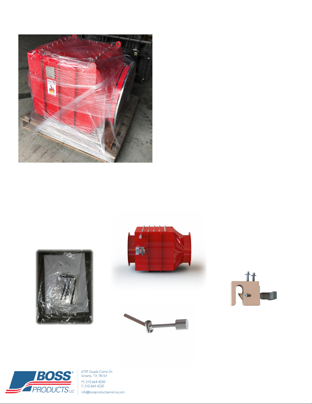
• e EcoMAXX® EM-NRV typically ships shrink-
wrapped and strapped on a wooden pallet. Custom-
er must inspect the equipment for damage upon
receipt. If damage is present, receiver must note
damaged on the shipping documents in order to le
a claim.
• All Counterweights are shipped inside the No Re-
turn Valve. Sizes 7 thru 28 have 1 counter weight.
Sizes 32” + Utilize 2 counterweights with patented
breaking elements.
• Dependent on the size of the No Return valve, the
O-EM-NRV-CP03 control panel, O-EM-NRV-MS
and O-EM-NRV-DLS are shipped in a cardboard
box placed on top of the valve or inside it.
R T EMAXX® EM-NRV
NRV S P A I
”-” S P
Items included in NRV shipment images, not to scale**
Counter Weight Arm
Locking Mechanism
Aircom manual with
metric Allen Wrenches
NRV Main Body

Page 10
NRV NA Sup. Manual 2020 - Second Edition - Version 0020
Print date: 6/26/2020
S : Remove bolt on counter weight mounting sha using
provided Allen wrench.
S : Slide counter weight onto mounting sha, then re-tighten
bolt using provided Allen wrench.
S : Position counter weight in the locked position of the
locking mechanism.
S : Tighten the two bolts on counter arm to secure counter
weight to mounting sha.
For mounting the microswitch and dust level sensor, refer to pages 13, 14.
” – ” A I
NRV S P A I

Page 11
NRV NA Sup. Manual 2020 - Second Edition - Version 0020
Print date: 6/26/2020
”+ S P
NRV S P A I
Locking Mechanism
(2x) Upper
Counter Weight Arm
(2x) Lower
Counter Weight Arm
Aircom manual with
metric Allen Wrenches
6x - Breaking Elements
”+ A I (P S)
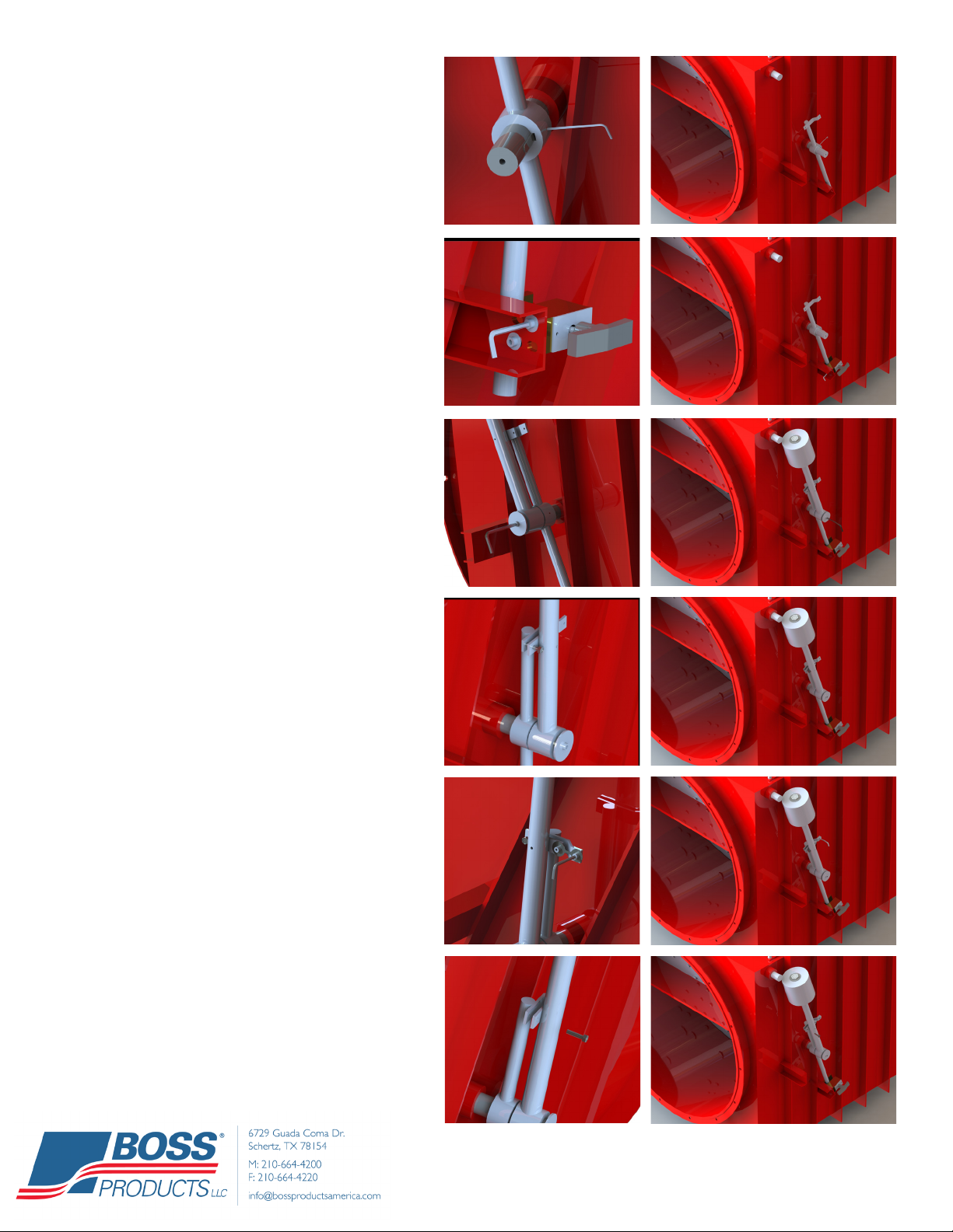
S : Remove bolt and washer.
S : Slide Arm on to the sha.
Note the slide key on the sha.
Page 12
NRV NA Sup. Manual 2020 - Second Edition - Version 0020
Print date: 6/26/2020
S : Secure arm in place by tightening the
set screw. Note: You will need to adjust arm once
locking mechanism is in place.
S : Install Locking mechanism onto the
mounting bracket of the EcoMAXX NRV. Note:
Ensure the handle is centered in the locking mech-
anism. If installed incorrectly, handle may rub or
stick preventing the counter weight from locking in
place during an event.
S : Slide counter weight onto the sha and
insert safety pin to keep counter weight in place.
S : Insert bolt and washer to secure the
counterweight onto the sha.
S : With safety bolt in place and counter-
weight secured, mount the breaking element to
the counterweight and tighten bolts. Note: Bolts
need to be snug. Do not over tighten, this may
damage the breaking element.
S : IMPORTANT!! Be sure to remove safe-
ty pin from the counterweight. Failure to do so will
cause the EcoMAXX No Return Valve to not close
fast enough during an event.

Page 13
NRV NA Sup. Manual 2020 - Second Edition - Version 0020
Print date: 6/26/2020
M M B (O-EM-NRV-MS)
S :
Secure Microswitch
S :
Remove screw and lever.
S :
Line up arrows and then
insert and tighten the
screw.
M M NRV
S :
Mount Microswitch to the locking mechanism using
the provided bolts.
S :
Rotate counterweight arm into the locked position.
Ensure arm is centered in the locking mechanism to
avoid obstruction. If not centered, the arm may not
fully close or lock during an event.
IMPORTANT U I S-U, “S
F” .
Page 14
NRV NA Sup. Manual 2020 - Second Edition - Version 0020
Print date: 6/26/2020
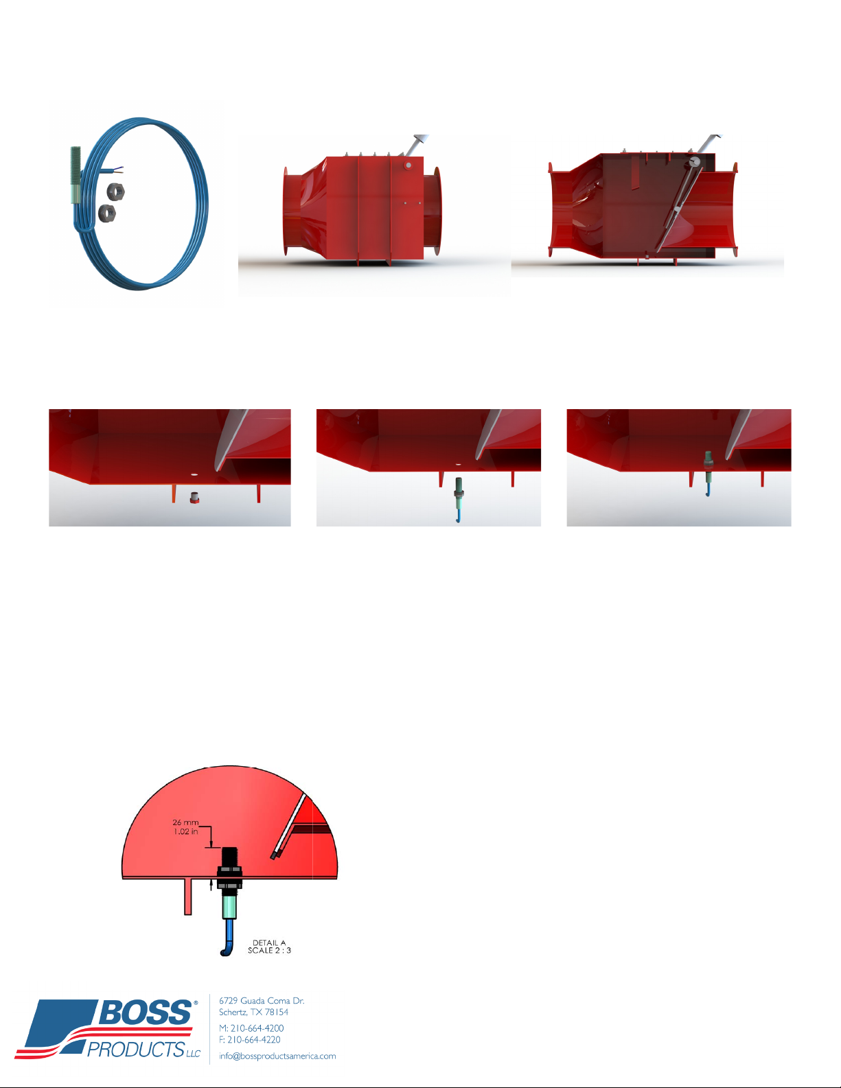
M D L S EMAXX NRV
S : Remove bolt on the bot-
tom side of the NRV.
S: : Install the rst
mounting ange onto the sensor.
Note: e drawing below species
the distances the rst mounting
ange should be from the top of
the sensor.
S : Insert sensor into
the bottom side of the NRV and
install second mounting ange on
the sensor. Adjust height of the
sensor to required height de-
scribed in the drawing provided.
D L S -R I H
D L S M F (O-EM-NRV-DLS)
Recommended Installation height of the rst
mounting ange. If the tip of the sensor is too
close to the bottom surface of the NRV, the sen-
sor will not function properly. Contrary, insert-
ing the sensor too deep will result with interfer-
ence from the ap valve.
**26mm from the bottom surface of the NRV.
NRV Side Prole NRV Cut View
Page 15
NRV NA Sup. Manual 2020 - Second Edition - Version 0020
Print date: 6/26/2020
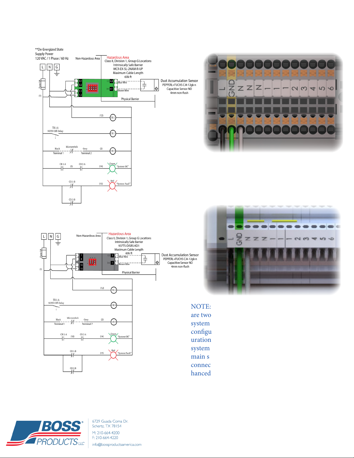
G W S EMAXX® C
NOTE: On the wiring diagram you will notice there
are two options provided for connecting to the main
system control panel. One is an individual alarm
conguration and the other is a general alarm cong-
uration. Choose the one that will work with your main
system control panel. You will need to refer to your
main system wiring diagram to determine how the
connection needs to be made. See below for an en-
hanced view of the 2 options.
To wire supply power connect line, ground,
and neutral wires to terminals L, GND, and
N as shown in the General Wiring diagram.

Page 16
NRV NA Sup. Manual 2020 - Second Edition - Version 0020
Print date: 6/26/2020
Connect low voltage control
wires to terminals 3 and 6 as
shown in the General Alarm
Conguration wiring diagram.
en use a jumper to connect
terminals 4 and 5.
Connect low voltage control
wires to terminals 3 and 4 as
shown in the Individual Alarm
Conguration wiring diagram.
en connect low voltage control
wires to terminals 5 and 6 as
shown in the Individual Alarm
Conguration wiring diagram.
Page 17
NRV NA Sup. Manual 2020 - Second Edition - Version 0020
Print date: 6/26/2020
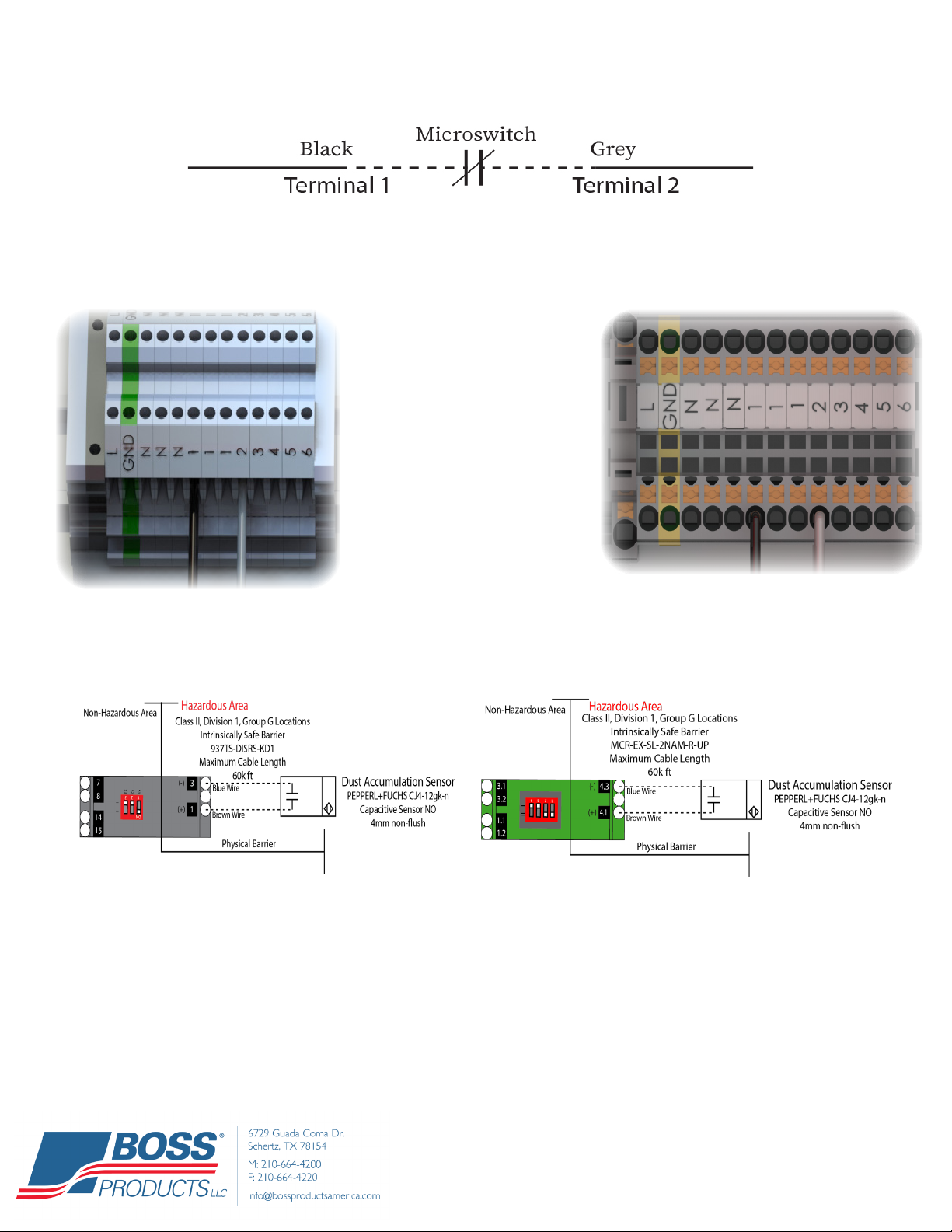
W M EMAXX® CP
Referencing the wiring diagram on page 15, the microswitch is connected
using terminals 1 and 2. When looking at the diagram, notice only the black
and grey wires are used for the microswitch connection.
W D L S EMAXX® CP
Connect the black wire to one
of the terminals labeled 1. en
connect the grey wire to the
terminal labeled 2.
**On the wiring diagrams you will notice that the Dust Level
Sensor will be installed inside the physical barrier inside of the
control Panel.**
Dust level sensor wiring must be in its own conduit.
Allen Bradley ISR: Connect the brown wire
to terminal 1 on the intrinsic relay barrier.
Connect the blue wire to terminal 3 on the
intrinsic relay barrier.
Phoenix Contact ISR: Connect the brown
wire to terminal 4.1 on the intrinsic relay
barrier. Connect the blue wire to terminal
4.3 on the intrinsic relay barrier.

Page 18
NRV NA Sup. Manual 2020 - Second Edition - Version 0020
Print date: 6/26/2020
G W S C (-)
Connect the brown wire to terminal 4.1 on
the intrinsic relay barrier. Connect the blue
wire to terminal 4.3 on the intrinsic relay
barrier.
W D L S CP
W M CP
Similar to the CP03, the black wire will land in the “24V+”
terminal and the gray wire will land in the “1” terminal.
Disregard all other wires from microswitch. (See below)
Jumper will be required between “24V+” and “2” (See
Below)
S I V CP
Terminals “U1” and “U2” will be used as a shut-
down signal in the CP04. When the CP04 is “OK”
the interlock contact will be closed. e contact
will open if any sensor faults. (Refer to above sche-
matic)
M C J C
(U U C S V) C

Page 19
NRV NA Sup. Manual 2020 - Second Edition - Version 0020
Print date: 6/26/2020
B D L S I P
C
In cases where an inspection protocol (NFPA 69: 2019, 12.2.3.4.5.2) is instituted in lieu of a
dust level sensor for dust accumulation monitoring inside of an EcoMAXX NRV the following
instructions must be followed to ensure the system remains running uninterrupted by a fault
alarm.
1. Press the Up or Down arrow until your
screen displays the system time and then press
the “ESC” key.
2. e system menu will come up, scroll using
the up and down arrows and press the “OK” key
when you nd “Program”.
3. Under the “Program” menu, select “Set Pa-
rameter” by pressing the “OK” key.
4. Under the “Set Parameter” menu, select “By-
pass DLS 1” and press the “OK” key.
5. Press the “OK” key until the word “O ” ashes. Scroll using the up and down arrows and change to “On”.
Press “ESC” when complete to exit all menus. Repeat steps 4 and 5 for DLS 2, 3, and 4 (if applicable).

Page 20
NRV NA Sup. Manual 2020 - Second Edition - Version 0020
Print date: 6/26/2020
EMAXX® NRV S/R P
Counter Weight Assembly
P/N: RP-EM-NRV-CWØ
NOTES:
Where “Ø” is noted specify
diameter of product.
Other replaceable parts not
noted may be available but
must discussed with Boss
Products to insure integrity
and functionality of the valve.
Locking Mechanism with
Mounting Bracket
P/N: RP-EM-NRV-LMB
Flanges and Co-Flanges
Flange P/N: EB-FLØ
Co-Flange P/N: EB-CFLØ
EMAXX® NRV C C (A S)
Control Panel
P/N: O-EM-NRV-CP03
Dust Level Sensor
P/N: O-EM-NRV-DLS
Microswitch
P/N: O-EM-NRV-MS
EMAXX® NRV R P S ” +
B E P
N
A
NRV S
P-EM-NRV-BE20 ”
P-EM-NRV-BE22 ”, ”
P-EM-NRV-BE30 ”, ”
P-EM-NRV-BE40 ”
This manual suits for next models
44
Table of contents
Other BOSSCO Control Unit manuals


Popular Control Unit manuals by other brands


Control Technologies
Control Technologies 5250-TI5 Installation and operation guide

Control Technologies
Control Technologies CTI 2451 Installation and operation guide

wink haus
wink haus FM.V.SW operating instructions

Delta
Delta DVP04DA-H instruction sheet

Kromschroeder
Kromschroeder IFD 244 operating instructions

VALCOBABY
VALCOBABY MCP-4 Series manual

IBC control
IBC control MicroMax750 manual

Alfalaval
Alfalaval 5308 instruction manual

E-Tech
E-Tech DrivE-Tech 015 Installing and operating manual

Qcells
Qcells Q.PEAK DUO XL-G11S.X / BFG Series Installation and operation manual

seeed studio
seeed studio MMA7660FC user manual

SIGMA TEK
SIGMA TEK ST 151 instruction manual