BOSSCO CLIMA AGR User manual
This document is to be used in conjunction with the full user guide available from
the manufacturer or to download at bossaccesstowers.com/literature.
Safe use
Please read this guide carefully. Please note that diagrams are for
illustrative purposes only.
• Check that all components are onsite, undamaged and that they are functioning
correctly - (refer to Checklist and Quantity Schedules in the user guide). Damaged or
incorrect components should not be used.
• Check ground on which tower is to be erected and moved is capable of supporting
the tower.
• The safe working load is 275kgs (606lbs), per platform level, uniformly distributed up
to a maximum of 950kgs (2100lbs), per tower (including self- weight).
• Beware of horizontal forces (e.g. power tools) which could generate instability.
• Maximum horizontal force equals 30kg.
• Towers must only ever be climbed from the inside and using the rungs directly below
the trapdoor.
• It is recommended that towers should be tied to a solid structure when left
unattended.
• Only use the adjustable legs to level the tower and not to gain extra height.
Adjustable legs should only ever be extended to minimum amount required to level
the tower.
Lifting of equipment
• Tower components should be lifted using a reliable lifting material (e.g. strong rope),
employing a reliable knot (e.g. clove hitch), to ensure safe fastening and always lift
within the footprint of the tower.
• Assembled mobile towers should not be lifted with a crane or other lifting device.
• Ensure the safe working load of the supporting decks and the tower structure is not
exceeded.
Movement
• The tower should only be moved by manual effort, and only from the base.
• No person or materials should be on the tower during movement.
• Caution should be exercised when wheeling a tower over rough, uneven or sloping
ground, taking care to unlock and lock castors. If stabilisers are fitted, they should
only be lifted a maximum of 25mm above the ground to clear ground obstructions.
• The overall height of the tower when being moved, should not exceed 2.5 times the
minimum base dimensions, or 4 metres overall height with stabilisers fitted in the
correct position (whichever is the smallest). If stabilisers are not fitted in the standard
position, the overall height of the tower should not exceed 2m.
• Before use, check the tower is still correct and complete.
• After every movement of the tower use a spirit level to check that it is vertical and
level to within 10mm/m and set the adjustable legs as required.
• Do not move the tower in wind speeds over 7.7 metres per second (17 mph).
• Mobile access towers are not designed to be lifted or suspended.
NOTE: If the tower is moved, you MUST inspect prior to use.
Ties
For further information on tying-in a tower please contact your supplier or the
manufacturer.
Maintenance - storage - transport
All components and their parts should be regularly inspected to identify damage,
particularly to joints. Lost or broken parts should be replaced, and any tubing with
indentation greater than 5mm must not be used.
PN3304600
Description Yes
Tower structure upright and level
Castors locked and legs correctly adjusted
Horizontal and diagonal braces tted
Stabilisers and props tted as specied
Platforms located and wind-locks engaged
Interlock clips engaged
Toe boards located
Guardrails tted correctly and positively locked
Tower designation information kit tted
Refer to this checklist before using each time.
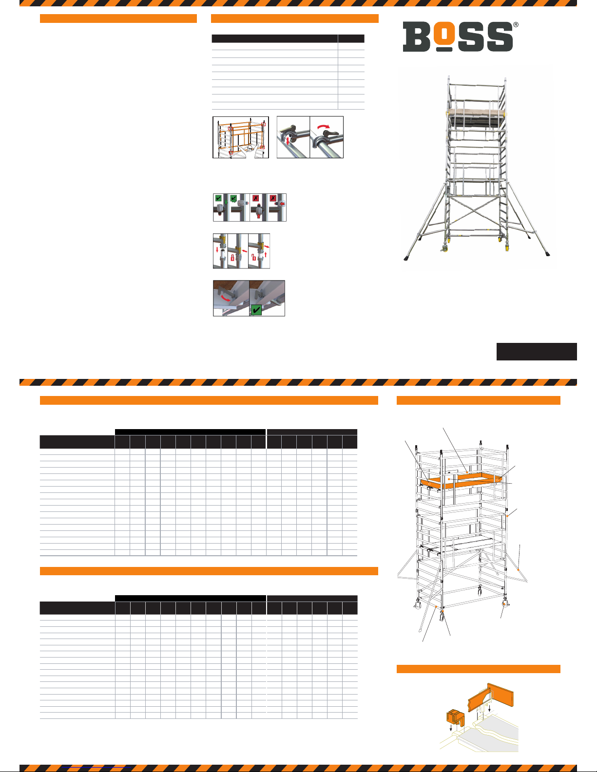
BoSS Clima 850 to EN 1004: Available in 2 lengths - 1.8m and 2.5m. Internal/external use - towers under 2.5m are outside of the
scope of EN 1004
QUANTITY SCHEDULE 1450 WIDTH TOWERS
BoSS Clima 1450 to EN 1004: Available in 2 lengths - 1.8m and 2.5m. Internal/external use - towers under 2.5m are outside of the
scope of EN 1004
End
Toe Board
BoSS Camlock Advance Guardrail
Side
Toe Board
Trapdoor
Adjustable Leg
4 Rung Frame
Castor
8 Rung
Frame
Stabiliser
Side Toe Board
End
Toe Board
Toe Board Clip
Claw
Rung
(A)
(B)
Deck
FITTING TOE BOARDS
Ensure horizontal braces and guardrails are tted correctly.
Ensure interlock clips on frame members are in the ‘locked’ position.
Ensure wind-locks are engaged before moving onto the deck levels.
Ensure camlocks are engaged.
Ensure horizontal braces and guardrails are tted correctly.
Always t as shown.
Refer to this checklist before using each time.
Internal or external use Internal use only
Component Working height(m)
Platform height (m)
4.2
2.2
4.7
2.7
5.7
3.7
6.2
4.2
6.7
4.7
7.7
5.7
8.2
6.2
8.7
6.7
9.7
7.7
10.2
8.2
10.7
8.7
11.7
9.7
12.2
10.2
12.7
10.7
13.7
11.7
14.2
12.2
125/150/200mm Castor 4 4 4 4 4 4 4 4 4 4 4 4 4 4 4 4
250mm Adjustable Leg 4 4 4 4 4 4 4 4 4 4 4 4 4 4 4 4
850 4 Rung Frame 2 2 2 2 2 2 2 2 2 2 2
850 6 Rung Frame 2 2 2 2 2 2 2 2 2 2
850 8 Rung Frame 2 2 2 4 4 4 6 6 6 8 8 8 10 10 10 12
1.8m/2.5m Trap Deck 1 2 2 2 3 3 3 4 4 4 5 5 5 6 6 6
1.8m/2.5m Horizontal Brace (Red) 2 2 2 2 2 2 2 2 2 2 2 2 2 2 2 2
2.1m/2.7m Diagonal Brace (Blue) 2 2 2 2 2 2 2 2 2 2 2 2 2 2 2 2
1.8m/2.5m Side Toe Board 2 2 2 2 2 2 2 2 2 2 2 2 2 2 2 2
0.6m End Toe Board 2 2 2 2 2 2 2 2 2 2 2 2 2 2 2 2
Toe Board Holder 4 4 4 4 4 4 4 4 4 4 4 4 4 4 4 4
1.8m/2.5m Camlock AGR 2 2 4 4 4 6 6 6 8 8 8 10 10 10 12 12
SP7 Fixed Stabiliser 4 4 4 4 4
SP10 Telescopic Stabiliser 4 4 4 4 4 4 4 4 4 4
SP15 Telescopic Stabiliser 4
Total Self-Weight of Tower (kg) - 1.8m 112 130 154 158 176 212 216 234 258 276 279 303 307 325 349 353
Total Self-Weight of Tower (kg) - 2.5m 124 147 173 177 200 239 242 265 292 310 318 345 348 371 398 401
Internal or external use Internal use only
Component Working height (m)
Platform height (m)
4.2
2.2
4.7
2.7
5.7
3.7
6.2
4.2
6.7
4.7
7.7
5.7
8.2
6.2
8.7
6.7
9.7
7.7
10.2
8.2
10.7
8.7
11.7
9.7
12.2
10.2
12.7
10.7
13.7
11.7
14.2
12.2
125/150/200mm Castor 4 4 4 4 4 4 4 4 4 4 4 4 4 4 4 4
250mm Adjustable Leg 4444444444444444
1450 4 Rung Frame 2 2 2 2 2 2 2 2 2 2 2
1450 6 Rung Frame 2 2 2 2 2 2 2 2 2 2
1450 8 Rung Frame 2 2 2 4 4 4 6 6 6 8 8 8 10 10 10 12
1.8m/2.5m Fixed Deck 1 1 2 2 2 3 3 3 4 4 4 5 5 5 6 6
1.8m/2.5m Trap Deck 1222333444555666
1.8m/2.5m Horizontal Brace (Red) 2 2 2 2 2 2 2 2 2 2 2 2 2 2 2 2
2.1m/2.7m Diagonal Brace (Blue) 2 2 2 2 2 2 2 2 2 2 2 2 2 2 2 2
1.8m/2.5m Side Toe Board 2 2 2 2 2 2 2 2 2 2 2 2 2 2 2 2
1.2m End Toe Board 2 2 2 2 2 2 2 2 2 2 2 2 2 2 2 2
Toe Board Holder 4 4 4 4 4 4 4 4 4 4 4 4 4 4 4 4
1.8m/2.5m Camlock AGR 2 2 4 4 4 6 6 6 8 8 8 10 10 10 12 12
SP7 Fixed Stabiliser 4 4 4 4 4
SP10 Telescopic Stabiliser 44444444444
Total Self-Weight of Tower (kg) - 1.8m 136 155 196 201 220 261 279 297 338 343 362 403 408 427 468 473
Total Self-Weight of Tower (kg) - 2.5m 153 177 226 231 255 303 321 345 393 398 422 471 475 499 548 553
©2017 WernerCo Rev. 12/17
Mobile Aluminium Tower with
Climbing Frames 850/1450
Camlock Advanced Guardrail
QUICK GUIDE
CLIMA AGR
QUANTITY SCHEDULE 850 WIDTH TOWERS COMPONENTS
PRE-USE SAFETY CHECKLISTSAFETY FIRST
PN3304600 BoSS_DL_Folded_Clima_AGR_Quick_Guide rev1217.indd 1 07/12/2017 15:14
During use
Wind description Beaufort scale Beaufort no. Speed in mph Speed in m/sec
Medium breeze Raises dust and loose paper, twigs snap off 4 8 - 12 4 - 6
Strong breeze Large branches in motion, telegraph wires whistle 6 25 - 31 11 - 14
Gale force Walking is difficult 8 39 - 46 17 - 21
• Beware of open-ended buildings, which can cause a funneling effect.
• Raising and lowering components, tools, and/or materials by rope should be conducted within the tower base. Ensure that the safe working
load of the supporting decks and the tower structure is not exceeded.
• The assembled tower is a working platform and should not be used as a means of access or egress to other structures.
• Beware of horizontal forces (e.g. power tools) which could generate instability. Maximum horizontal force 20kg.
• The stairway towers, featuring an inclined staircase access, are for frequent use by personnel carrying tools and/or materials.
• Do not use boxes or stepladders or other objects on the platform to gain extra height.
Beware of high winds in exposed, gusty or medium breeze conditions. We recommend that in wind speeds over 7.7 metres per second
(17mph), cease working on the tower and do not attempt to move it. If the wind becomes a strong breeze, (expected to reach 11.3 metres per
second - 25 mph) tie the tower to a rigid structure. If the wind is likely to reach gale force, (over 18 metres per second - 40 mph) the tower
should be dismantled.
For a detailed user guide, please go to
bossaccesstowers.com/literature
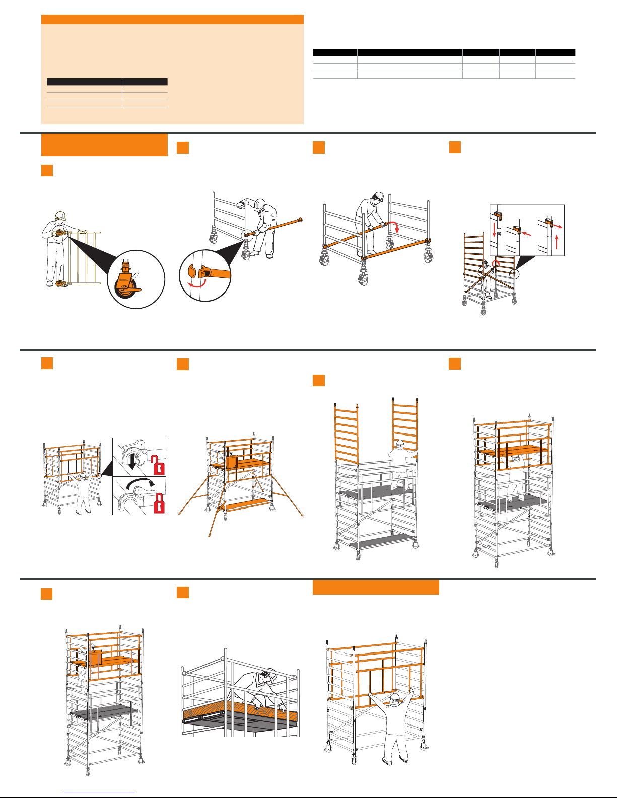
Push four castors onto four adjustable legs. Insert adjustable
legs into two end frames as shown. Lock castor brakes.
Base plates can be tted to adjustable legs if it is not necessary to
move the tower.
1
Fit one horizontal brace (red) onto the vertical of an end
frame, just above the bottom rung, with the claw facing
outwards.
Note: All locking claws must be opened before tting.
2Position the second end frame as shown and t the other
end of the horizontal brace on to the vertical, just above the
bottom rung. Fit a second horizontal brace on the bottom rungs on
the other side of the frames to square the tower.
3Fit two additional end frames and check the frame
interlock clips are engaged. Fit two diagonal braces (blue)
in opposing directions, from the 2nd rung to the 6th rung on the
opposing side. Ensure the frames are vertical and level by checking
with a spirit level and setting the adjustable legs as required.
IMPORTANT - Only use the adjustable legs to level the tower
and not to gain extra height.
4
Fit two more AGRs to the end frames, with the top claws on
the 20th rungs. Fit a trapdoor deck on the 16th rung, with the
trapdoor in line with the one below. Place a xed deck on the 16th
rung next to the trapdoor deck.
The tower now has a platform height of 4.2m. If nishing at this
height, move on to Step 10. If greater platform heights are required,
move on to Step 9.
The manufacturer recommends that two persons are used to
build BoSS Towers. Above 4m height, it is essential that at least
two persons are used.
Only climb the tower from the inside.
Always start building with the smallest height frames at the base
of the tower:
ASSEMBLY PRINCIPLES
Platform height in metres Frame at base
2.2, 4.2, 6.2, 8.2, 10.2, 12.2 4 rung
2.7, 4.7, 6.7, 8.7, 10.7 6 rung
3.7, 5.7, 7.7, 9.7, 11.7 4 & 6 rung
850 & 1450 towers:
ASSEMBLY PROCEDURE
AGR Method
8
Continue to add pairs of end frames, AGRs and t decks as
shown in the previous steps.
Continue until the required height is reached.
9Fit the toe boards - see the components section for guidance
on how to t.
The tower is now complete.
10
Unlocked
Locked Locked
INTERLOCK CLIP
Locked Unlocked
Fit an AGR on both sides of the tower. The bottom of
the AGR must be tted to the 6th rung of the tower, as
shown. The AGR should be placed up against the end frame
verticals.
5Fit the stabilisers. If required, t a temporary deck on the
lowest rungs of the tower. Fit a trapdoor deck on the 8th
rung on one side of the tower. Ensure the trapdoor is positioned with
the hinges towards the outside of the tower as shown. Fit a xed
deck next to the trapdoor deck on the 8th rung. The platform is now
complete. Climb the end frame below the trapdoor on the inside of
the tower.
If tted, remove the temporary deck from the lowest rungs.
6
Fit two additional end frames.
7
NOTE: The following diagrams show the tower without
stabilisers to improve clarity of views.
DISMANTLING PROCEDURE
To take down the tower reverse the building sequence. Unlock the
camlocks at the bottom of the AGR frame, then lift off the AGR from
the end frames.
Where all three frame heights are used in a tower, start with 4
rung frames at the base, with the 6 rung frames next and the
8 rung frames on the top. Refer to the Quantity Schedules for
detail. The procedure illustrated shows a 1450 tower starting
with a 4 rung frame and a platform height of 4.2m. If building an
850 tower, the following method can be used with single decks
at all levels.
PN3304600 BoSS_DL_Folded_Clima_AGR_Quick_Guide rev1217.indd 2 07/12/2017 15:14
Other manuals for CLIMA AGR
1
Table of contents
Other BOSSCO Desktop manuals


