Bosslan BOSSC158 User manual

%266&USER MANUALV1.3

CATALOGUE
THE 1ST CHAPTER DESCRIPTION OF PRODUCT ...................................................................3
1.1 PACKING...........................................................................................................................3
1.2 THE LOWEST SYSTEM CONFIGURATION .................................................................3
1.3 FEATURES ........................................................................................................................4
THE 2 INSTALLATION OF IP CAMERA.....................................................................................4
2.1 INSTALLATION PREPARATION...................................................................................4
2.2 HARDWARE INSTALLATION........................................................................................5
2.3 SOFTWARE INSTALLATION.........................................................................................5
3.1 GET IP ADDRESS OF IP CAMERA IN INTERNAL NETWORK..................................7
3.2 SOFTWARE EDITION UPDATE .....................................................................................9
3.3. LOGIN THE CONFIGURATION PAGE OF IP CAMERA.............................................9
3.4 REAL-TIME MONITORING ..........................................................................................10
3.4.1 Visitor Operating....................................................................................................11
3.4.2 OPERATOR OPERATING...................................................................................11
3.5 ADMINISTRATOR OPERATING..................................................................................12
3.5.1 DEVICE INFORMATION.....................................................................................12
3.5.2 DEVICE NAME SETTINGS.................................................................................13
3.5.3 DEVICE CLOCK SETTINGS...............................................................................13
3.5.4 DEVICE USER SETTINGS..................................................................................14
3.5.5 MULTI-CHANNEL DEVICE SETTINGS ...........................................................14
3.5.6 BASIC NETWORK SETTINGS...........................................................................16
3.5.7 WIRELESS LAN SETTINGS...............................................................................17
3.5.8 ADSL SETTINGS .................................................................................................17
3.5.9 UPNP SETTINGS..................................................................................................17
3.5.10 DYNAMIC DOMAIN NAME SETTINGS.........................................................18
3.5.11 MAIL SERVICE SETTINGS..............................................................................18
3.5.12 FTP Service Settings............................................................................................19
3.5.13 ALARM SERVICE SETTINGS..........................................................................20
3.5.14 SYSTEM SOFTWARE UPGRADE....................................................................21
3.5.15 Backup & Restore Settings ..................................................................................21
3.5.16RESTORE FACTORY DEFAULT SETTINGS ..................................................22
3.5.17 DEVICE REBOOT..............................................................................................22
3.5.18 log ........................................................................................................................22
3.5.19 RETURN..............................................................................................................23
THE 4TH CHAPTER HOW TO VIEW IP CAMERA...................................................................23
4.1 LAN VIEW.......................................................................................................................24
4.2 INTERNET VIEW............................................................................................................25
4.2.1 CONNECT INTERNET THROUGH ADSL DIRECTLY....................................25
4.2.2 CONNECT INTERNET BY LAN.........................................................................27
THE 5TH CHAPTER TECHNICAL PARAMETER.....................................................................29
5.1 KEY FUNCTIONS...........................................................................................................29
5.2 KEY PARAMETERS.......................................................................................................30

THE 6TH CHAPTER APPENDIX.................................................................................................30
6.1 RESTORE FACTORY DEFAULT SETTINGS ..............................................................30
6.2 TROUBLE SHOOTING...................................................................................................30
THE 1ST CHAPTER DESCRIPTION OF PRODUCT
1.1 PACKING
Packing in detail as follow (If find any missing parts , please contact your supplier
immediately):
1、IP CAMERA, Bracket
2、Driver
3、Power Adapter
4、B-B Network Cable
Description of IP CAMERA, please refer to Picture 1.1 and 1.2
1.2 THE LOWEST SYSTEM CONFIGURATION
The lowest system configuration of your PC when use this IP Camera
1.Pentium III CPU or above, 1GHz frequency or higher
2. 256M built-in memory or above
3. 10M network card or above
4. Operating System: Windows XP, Windows 2000 or above;
Install internet explorer 4.0(or above) browser, we suggest you to use internet explorer
6.0/7.0 Browser for view.

1.3 FEATURES
Easy installation—IP CAMERA is an independent system, with built-in CPU and
picture decoder; Just one power adapter and LAN connection can make it work.
Suitable for home, office and public place----No matter monitoring of home, office
or public place,or for amusement only, this IP Camera can match your needs Support
multiform protocols---TCP/IP network protocol, SMTP protocol, HTTP protocol and
other protocols related to internet.
Simple configuration---with standard Web browser in administrator interface.
Administrator can control and manage IP Camera by LAN or Internet.
Viewing/Recording--- clear user interface to view real-time pictures. Even when you
leave for a while,IP CAMERA will record the pictures and transfer files to your PC. Files
will be saved in the form of standard windows media, suitable for extensive application
program.
Dynamic Monitoring---capturing any tiny pictures and send to your mail box. IP
CAMERA will automatically compare the two continuous pictures and find out the changes
caused by moving.
Support DDNS---In order to view the pictures by internet, users must know the
gateway IP address when using IP CAMERA . However, if your gateway IP address is
dynamic, you must have dynamic domain server. As usual, many of the gateway don’t
support dynamic domain service, So it is limited when using IP CAMERA .
User management---If require, only authorized users can view real-time video, and
before that, users must enter their user names, passwords. Maximum users: 8 persons
The 2nd Chapter
THE 2 INSTALLATION OF IP CAMERA
Quickly view the installation manual, after finishing the procedures step by step, IP
CAMERA will work accordingly. IP CAMERA can be used in LAN, you will find the IP
address in LAN by carrying out IP Camera Tool program on PC,then input this IP address
into the IE browser address field ( such as http://192.168.1.100/),so it can connect IP
CAMERA and camera nterface can be shown on browser page. For external
network visit, a prior suitable configuration of IP Camera in LAN is required, please
refer to the instructions in the following chapters.
2.1 INSTALLATION PREPARATION
Please make sure you have already read the user manual carefully and know well
about the functions and configurations of IP CAMERA before installation. Then, use the

enclosed network cables to connect IP CAMERA to Internet, via router or switch. Please
prepare the router and switch by yourself.
2.2 HARDWARE INSTALLATION
This part is for introducing how to finish hardware installation and physical connection
of IP CAMERA. After it, please connect power supply, IP CAMERA will start work and the
indicator light will shine.
1.Install the IP Camera at the place where monitoring required.
2.connect network
Connect IP Camera with hub (10/100M) or switch (10/100M), insert one end of the
network cable into RJ45 port, the other end into router or switch. Indicator light at RJ45
port will flash under normal condition
3.connect to the power supply
Pleaser use the enclosed power adapter in package to connect the IP Camera and power
supply, otherwise you will damage the hardware
4.check LED light
After connect to the power supply, IP Camera will start work and the small yellow light
at the back of it will shine. In dark condition, you will see the light at the front of camera.
Four infrared lights will be as lamp-house to let you see clear picture in dark.
2.3 SOFTWARE INSTALLATION
Please use the enclosed IPCAMSETUP.EXE software to start initial installation on
your PC. After it, IP Camera Tool will search all IP addresses of IP CAMERA in the same
network space automatically.
1.Please use the enclosed driver, then you will see the welcome interface of
installation program.
2.Introduction interface of installation will be shown. After read it, press” Next” to
continue installation.
Please refer to Picture 2.4

Picture 2.4: Installation interface 1
3. Installation guidance will help you to finish the installation. Please press “NEXT”
buttons in turn, pleaser refer to Picture 2.5
Picture 2.5: continue the installation
4.When finish the installation, please restart your computer. Please refer to Picture
2.6 .

Picture 2.6 : finish installation
THE 3RD CHAPTER CONFIGURATION OF IP
CAMERA
After finish the 2nd chapter, IP CAMERA can work in LAN. We can find the IP
address of IP CAMERA by IP Camera Tool program and visit IP CAMERA by browser.
(input IP address and port number of IP CAMERA into the IE browser address field, such
as “http://192.168.1.112:100 / http://192.168.1.1:100”,then press” enter”. If the port number is 80,
then you can input IP address http://192.168.1.112 directly, without port number),
Please note that our factory default setting of the port number is 80 .
Now we can configure IP CAMERA by operating web configuration page . If you want
to view the monitoring picture by browser, or to operate IP CAMERA web configuration
page, you should know the IP address and port number of IP CAMERA .
We supply IP Camera Tool Program, which is used for searching IP address and port
number of IP CAMERA in LAN only (both IP CAMERA and our PC are in the same
network space), but not for searching IP address and port number of IP CAMERA in
external network( IP CAMERA and our PC are not in the same network space).If we want
to visit IP CAMERA through external network, we must configure IP CAMERA in LAN at
first.
About how to make a external network visit or detail information of setup, please refer
to the following descriptions.
3.1 GET IP ADDRESS OF IP CAMERA IN INTERNAL
NETWORK
Please pay attention to the below instruction before getting IP address
1. double press IP Camera Tool.
2.As the following dialog box on PC: You will see the IP address after more than 10
seconds, if camera connect to the power supply just for a minute.
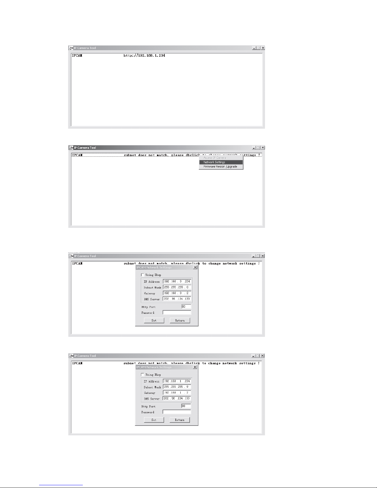
3.If the camera is not in the same network space, please do as followed:
4 Click the left button of the mouse to choose the prompts and click right button to
select the related items, as shown below:
5 make a manual change as the picture show

Please do not choose “automatically get IP”, if your LAN or PC doesn’t support DHCP.
You can set up the camera IP address according to the network space of LAN or PC, but it
should be different from that of other devices or PC in the same network space( the first 3
items and subnet mask should be same) . You can change the port setting on the page
only.
Please choose “automatically get IP”, if your LAN or PC supports DHCP.
3.2 SOFTWARE EDITION UPDATE
IP CAMERA supports the upgrade of system software and application software,
application software applicable for interface upgrade.
3.3. LOGIN THE CONFIGURATION PAGE OF IP
CAMERA
If input the IP address of IP CAMERA into the IE browser address field and press
“Enter”,or directly double press the listed IP address in the dialog box of IP Camera Tool,
IE browser will be start up automatically and the administrator login window will also
appear.
Input the user name, password (the defaulted user name: admin, the defaulted
password : leave it blank), click “sign in” to view the monitoring page (supports
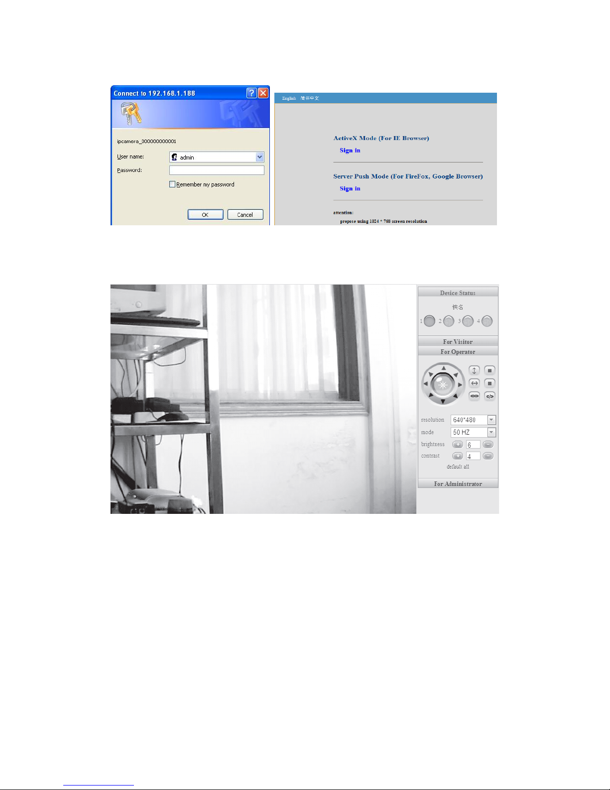
synchronous view of maximum 8 users )。
3.4 REAL-TIME MONITORING
(Control Area)
Notice: If no picture shown for the first-time use, you can set the user-defined security
grade of option “Internet” of IE browser: namely, unsigned control can be set up as the
status of “ startup prompt”

3.4.1 Visitor Operating
working status for each channel as followed:
3.4.2 OPERATOR OPERATING
Click , to set up following parameters
PTZ control Resolution: GA(640 X 480)/ QVGA(320 X 240)

3.5 ADMINISTRATOR OPERATING
Click , to enter into administrating page.
3.5.1 DEVICE INFORMATION
Click , please refer to the following picture:

The sequence number of the device: our factory sequence number.
Edition of system firmware of device: edition of system software of IP CAMERA
Edition of application firmware of device: edition of application software of IP
CAMERA
3.5.2 DEVICE NAME SETTINGS
Click , please refer to the following picture:
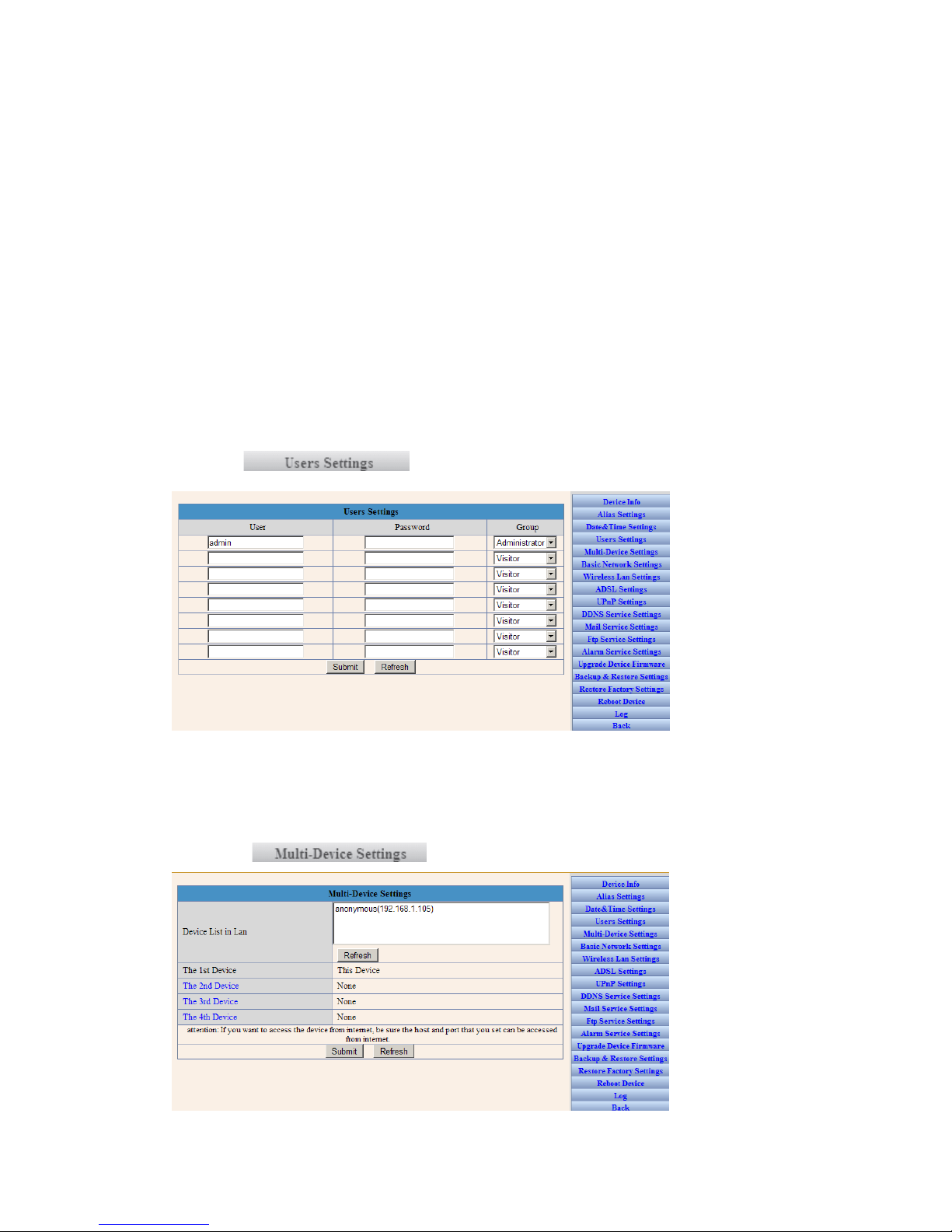
, please refer to the following picture
IP CAMERA can set up maximum 8 users and permissions
3.5.5 MULTI-CHANNEL DEVICE SETTINGS
Click , please refer to the following picture
For example: add the 2nd channel image
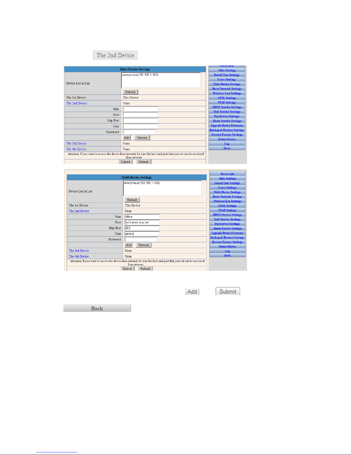
Click , please refer to the following picture:
IP CAM的Host,Http Port ,User, Password
Input the Host ,Http Port, User, Password, Click ,then ,and then
to switch
to 4-picture monitoring mode, as following:
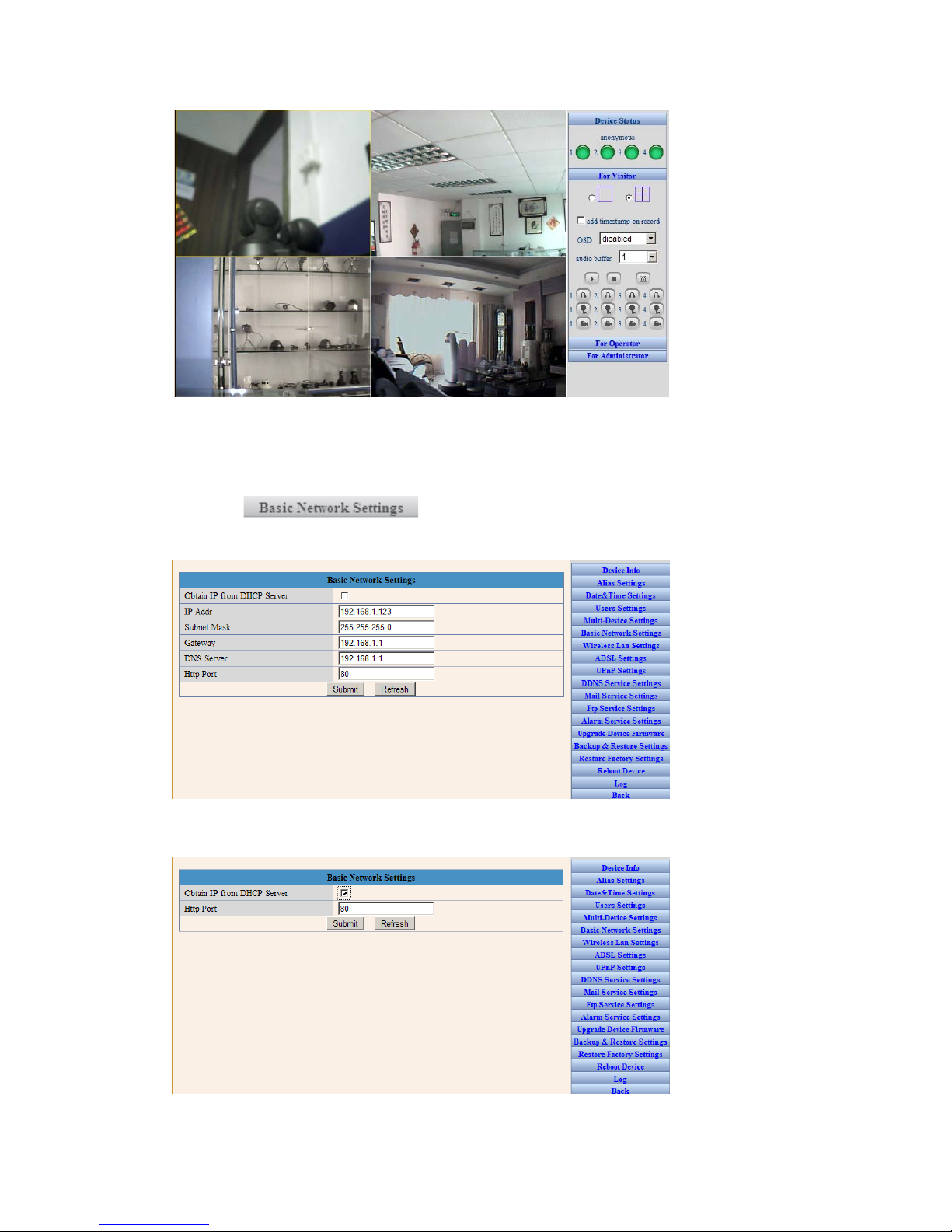
3.5.6 BASIC NETWORK SETTINGS
Click , please refer to the following picture. For example,
the IP address of this device can be set up as follows:
Please set up IP address, subnet mask, gateway, DNS server well. Dynamic IP setting
also available
Please choose and click for confirmation.

3.5.7 WIRELESS LAN SETTINGS
Click , please refer to the following picture. If WIFI is
required, please set it up as follows: available wireless network information can be scan
out and make a list.
Please choose and click for confirmation.
3.5.8 ADSL SETTINGS
Click , please refer to the following picture, with the
purpose of connecting ADSL.
3.5.9 UPNP SETTINGS
Click , please refer to the following picture. It is

unnecessary If the router does not have this kind of function.
3.5.10 DYNAMIC DOMAIN NAME SETTINGS
Click , please refer to the following picture:
DDNS Service: Fill in the web address for applying the domain name
DDNS User: Fill in the domain name
DDNS Password: Fill in the password of the domain name
DDNS Domain Name: DDNS domain name will automatically get the IP if connect well.
DDNS Status: Display the status of connecting the domain name
It will be necessary to set up this function if you want to make a visit through Internet.
Please choose and click for confirmation
3.5.11 MAIL SERVICE SETTINGS
Click , please refer to the following picture
This is with
mail alarm function: if any movement was detected, it will send message to the email box
which we have set up.
Sender: Fill in the e-mail address of senders
Receiver: Fill in the e-mail address of the receiver ( 4 receivers’ e-mails can be set up
synchronously
SMTP Server: Fill in the server address of the sender’s e-mail
SMTP User Fill in the user name of the sender’s e-mail
SMTP Password: Fill in the password of the sender’s e-mail
This function can be effected only if the camera has been connected to Internet; It is
necessary that the newly-revised password will be same as the e-mail password
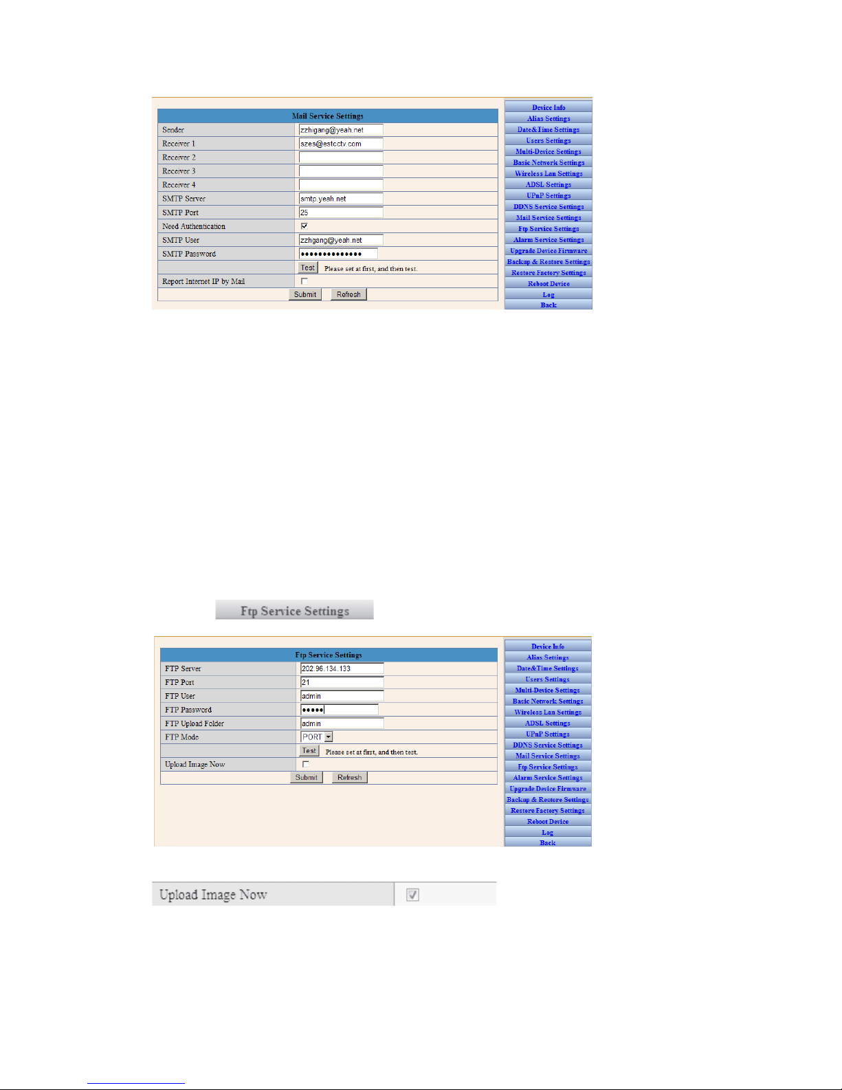
3.5.12 FTP Service Settings
Click , please refer to the following picture:
This function is
to upload the pictures to the Internet.
FTP Server: Fill in the web site to be uploaded
FTP Port: Fill in the FTP Port
FTP User: Fill in the FTP user name
FTP Password: Fill in the password of the FTP user
FTP Upload Folder: Fill in the file name to be uploaded
FTP Mode: Select PORT
Upload Image Now: Click it if needed
Upload Interval: setup the interval; Unit : second
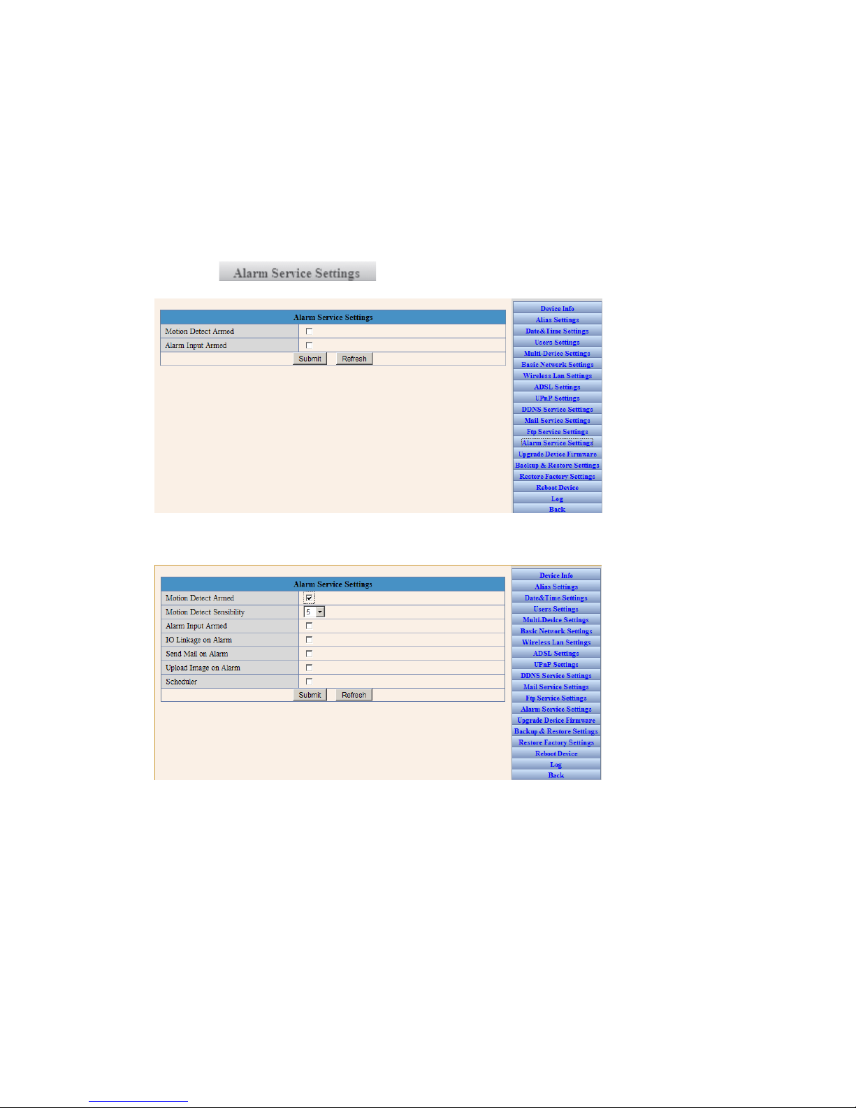
3.5.13 ALARM SERVICE SETTINGS
Click , please refer to the following picture
Select the alarm mode. For example, if select motion detection mode, you can refer to the
following pictures:
Select Alarm Mode by yourself: IO linkage, or e-mail sending, or image upload
Following information is an example for selecting the method of email sending:
Table of contents
Other Bosslan IP Camera manuals


