Boste UDC102 User manual

1
PRODUCT
MANUAL
Boste BK Series
(UDC102 Undersink Dispenser Model)

2
Product
Manual
BK Series (UDC102 Models)
Contents
1. Introduction . . . . . . . . . . . . . . . . . . . . . . . Page 3
2. Specifications . . . . . . . . . . . . . . . . . . . . . . . Page 4
3. Main Components . . . . . . . . . . . . . . . . . . . . . . . Page 5
4. Installation Guide . . . . . . . . . . . . . . . . . . . . . . . Page 7
5. Operation Guide . . . . . . . . . . . . . . . . . . . . . . . Page 8
6. Maintenance Guide . . . . . . . . . . . . . . . . . . . . . . . Page 9
7. Fault Diagnosis Guide . . . . . . . . . . . . . . . . . . . . . . . Page 10
8. Diagrams & Parts Guide . . . . . . . . . . . . . . . . . . . . . . . Page 16

3
Introduction
Please Note: This Product Manual is intended for use by qualified Service Technicians only.
Use of the advice and material enclosed by the end-user could invalidate product warranty,
occupational insurances and present health and safety risks.
We strongly recommend that this Product Manual is not left with the dispenser or end-user but that
instead training is given regarding the simple function operations.
The Boste BK Series (UDC102 Model) is a range of undercounter water dispensers that are connected to the mains water
supply and dispense water through a proprietary swan-neck faucet that is mounted on a worksurface.
There are two models in the range:
BK5 –Cold & Ambient
BK9 –Cold, Sparkling & Ambient
Both models
models
have
robust steel framed cabinets
and
attr
activ
el
y
injection moulded
plastic front, side and top
panels.
An
IEC
Power Lead is
supplied
for
connection
to the
IEC
socket
found on the
rear
of all
models
(An
additional
Schuko
type is
supplied
for the
European
mark
et).
Both are Direct Chill cold water
dispenser
where water is used as the cooling
medium
in the Direct Chill tank.
This
is automaticall
y
filled and
controlled
by the level control
system
upon
installation.
This tank is then chilled via
the
outer
e
v
a
por
a
tion
coil of the capillary
controlled refrigeration compression sys
tem.
We
recommend
fitting a
Pr
essure
Reducing
V
a
l
v
e
is fitted to all
supplies
to
regulate
the
pressure
to 3.5 bar/355 kPa.
On the carbonated water model,
water is chilled as it
passes through
the coil
immediatel
y
before
dispense
or
being
pumped
under
pressure
into
the carbonator
which it fitted inside the
same
coil. The
carbonator
is also
level
controlled
and allows the
sparkling
eff
ect
to occur
through saturation
with CO2.
Dispense
is at inlet
pressure and controlled
via the solenoid
v
a
l
v
es.
The Cold
T
e
mperatur
e
is
thermos
taticall
y
controlled
via the
adjustment
screw on the back of the
machine. This
setting
is factory set and is not
necessary
to adjust in most
cases
The Cold Tank can be
drained
via the two Drain
Port
on the
rear
of the
machine.
The level control
system
also
incorporates
a leak
detection
device within the
cabinet
which
switches
the
machine
off in the event of
detecting wate
r
.
4
Specifications
COOLING SYSTEM
High efficiency compression system with capillary control.
Premium quality long life hermetic compressor. Compact
internal condenser –fan assisted for greater efficiency.
Environmentally friendly R134A refrigerant.
3.5 litre stainless steel chiller tank with level control containing
stainless steel cold water direct chill coil.
Stainless steel carbonator tank with independent level control
fitted inside coil.
High capacity, low voltage diaphragm pump feeding
carbonator on sparkling water machine option.
COLD TEMPERATURE
2°C to 11°C.
THROUGHPUT PER HOUR
18 litres cold < 12°C / 16 litres sparkling <12°C.
DISPENSE
Swan Neck Faucet with ergonomically designed and
situated light touch sensitive controls.
MAXIMUM RUNNING
POWER CONSUMPTION
85-100 watt. Cooling. (Additional intermittent carbonation
usage).
POWER REQUIREMENTS
230 volt/50Hz 16A supply required.
POWER SUPPLY
IEC Power FusedSocket.
WATER CONNECTION
Mains in (3.5bar max) - 1/4” Push Fit/Faucet - 6mm Push Fit .
CO2 CONNECTION
1/4” Push Fit.
UNDERCOUNTER
DIMENSIONS
(w x d x h) 230 x 360 x 390mm
WEIGHTS
BK5 (M102)
Unit only - 15.0 kg/Faucet - 1.3kg
BK9 (M102)
Unit only - 17.1 kg/Faucet - 1.3kg
Boste BK Series
5
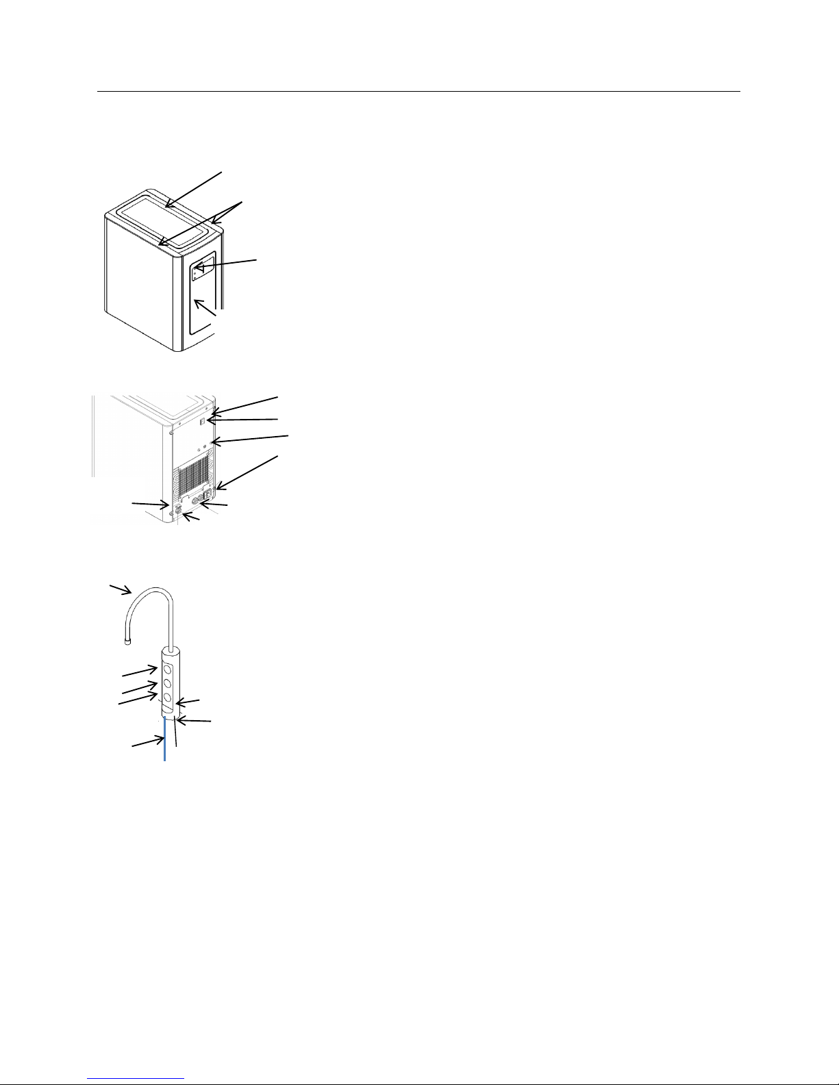
Threaded Stem & Back Nut
Main Components
Undersink Unit
BK5 Cold & Ambient BK9 Cold, Sparkling & Ambient
1no UDC102A Undercounter Unit 1no UDC102AS Undercounter Unit
Complete with: Complete with:
1no 2.0m Power Cordset 1no 2.0m Power Cordset
1no 1.0m Faucet Connection Harness 1no 1.0m Faucet Connection Harness
1no CO2 Regulator with gauge
Electronic Swan Neck Faucet
1no Electronic Swan Neck Faucet 1no Electronic Swan Neck Faucet
Complete with: Complete with:
2 - Button Membrane Switch 3 - Button Membrane Switch
1.0m x 6mm Insulated Water Pipe 1.0m x 6mm Insulated Water Pipe
Also included: Also included:
2.0m x 1/4” Faucet Connection Pipe 3.0m x 1/4” Faucet Connection Pipe
1.0m Faucet Connection Pipe Insulation 2.0m Faucet Connection Pipe Insulation
2no ¼1/4” Stem Elbow 5no ¼1/4” Stem Elbow
1no 1/4” Y Fitting 1no 1/4" Cross Fitting
1no 1/4" Male Threaded Adaptor 1no 1/4" Male Threaded Adaptor
1no 6mm Female Threaded Adaptor 1no 6mm Female Threaded Adaptor
Mains Installation Kit & Filters:
These are supplied as extra items according to individual ordering requirements
Top Panel
Side Panel
Front Panel
LED
Indication
Panel
On/Off Mode Switches
Power in
Thermostat
Water in & CO2 in
connections
Faucet
Connection
Water out connections
Swan Neck
Button
Switch
Panel
Ambient
Sparkling
Cold
Water Pipe
Elec
Connection
Back Panel

Boste BK Series
6
Installation Guide
1. Unpack both the undersink unit and the swan-neck faucet, checking the main components are present as per the
lists above. Dispose of the packaging in a responsible manner. Please note regarding any Mains Installation parts.
2. Check the thermostat set point of the undersink unit.
It should be preset to the following position:
-C
NB: Turn clockwise to
decrease
water
temperatur
e
3. Identify a suitable location for the unit. It should be positioned within 1.0m of the faucet, and within 2.0m of a
suitable services connections:
Water: Mains potable water –2.0bar recommended. Min 1.0bar
Electricity: 16A supply –Earth Leakage Protected.
Always install internally. Do not expose to dampness or moisture. There should be 150mm minimum behind the
unit, 25mm min each side and 100mm above. Always ensure there is adequate airflow around the unit.
Additional ventilation grills or extraction may be required.
When planning and providing for the connection to the services, always allow for easily accessible service
isolator fittings and for the position of an external water filter.
Allow also for the CO2 cylinder when installing a carbonated model.
4. Provide service connections as required.
5. Position the unit in place, ensuring it is level and stable.
6. Connect to the water supply. The maximum recommended inlet pressure is 3.5bar.We recommend fitting a check
valve, a pressure reducing valve and a „Waterbock‟ device. (These are available as part of our optional
Installation Kit). When fitting a Waterblock device we recommend a minimum setting of „2‟ be used. Pre-flush and
fit the filter in an accessible position and always allow adequate connecting pipe length to enable the unit to be
sufficiently moved for any future disconnection. Do not turn the water supply on at this stage.
7. Identify a suitable position for the swan neck faucet. A 33-35mm (max) hole is required. When positioning to
drain over an existing sink bowl, allow for the reach of the swan neck or otherwise the position of any optional
drip tray. Also allow for the height of the swan neck under any overhanging cupboard/shelf and for the space
needed for forming the needed hole. Relate the selected position to the undersink of the worksurface and check
for any obstructions. Allow sufficient space for fitting a back nut to the faucet stem.
8. Carefully form the needed hole, using the correct type of cutter for the worksurface material. Observe all local
occupational health and safety requirements.
9. Remove the back nut and washer from the faucet and carefully feed the connecting pipe tail and ribbon cable
through the hole formed in the worksurface. There is an integrated sealing O ring pre-fitted in the base of the
faucet but it may be necessary to apply a thin bead of silicone sealant also.
10. With the faucet membrane switch in the right position, carefully refit the back washer and nut. Take care not to
overtighten.
+C

Boste BK Series
7
2no
Adaptors
5no Stem
Elbow
Insulated Faucet Pipe
11. Connect faucet pipework as follows:
Cold & Ambient Model: Cold, Sparkling & Ambient Model:
-Fit Stem Elbows directly to water outlets on back of unit.
-Fit 30mm pieces of pipe to each.
-Fit Y or Cross Fitting.
-Fit 30mm piece of pipe
-Fit male threaded adaptor fitting
-Fit female threaded adaptor fitting
-Connect to insulated faucet pipe
12. (Sparkling Model only). Unpack CO2 Regulator and fit elbow fitting to spigot outlet. Check the control knob is oin
the fully closed position (anticlockwise). Carefully screw fit to a new, full CO2 single use cylinder ensuring the
small pressure relief vent in the stem is facing away from you or anyone else. Hand tighten securely. Connect to
the CO2 inlet on the back panel using the required length of ¼1/4” pipe. Stand cylinder in a suitable place.
13. Fit optional Drip Tray at this stage (if selected)
14. Turn on the water supply and check for any leaks.
15. Connect the IEC power cordset to the electricity supply. The Direct Chill system should now be heard to begin
filling. This may continue for a few minutes depending upon water pressure. (NB: Any immediate whining noise
from the DC pump should soon stop as the water level in the system rises).
16. Upon the filling cycle completing, proceed to flush the cold and the ambient water channels using these buttons on
the faucet control panel. We recommend that a minimum of 10lts is flushed through the unit*. (Cold approx. 8 lts
and Ambient approx. 2 lts). Switch on the Cooling Mode and allow up to 1 hr for the initial cooling cycle.
17. (Sparkling Model only). Switch on Sparkling Mode and allow the carbonation tank to fill. (The carboanntion pump
will run for approx. 15-20 secs). Upon completion, open the CO2 Regulator Knob and set initially to 5 bar. Flush
through approx. 10 lts of water using the sparkling button*. Depending on the inlet water pressure, you may have
to pause approx. every 500ml to allow the carbonation tank to refill. Reset the CO2 pressure to the required level.
We recommend 3-5bar (max) depending on individual requirements. Allow up to 1 hr for carbonation to develop.
*NB: The integrated leak prevention control will prevent any continuous dispense of >60 secs and could occur
while carrying out this prolonged dispensing. When it occurs the dispense will stop and a bleeping noise will
sound. To reset momentarily release the button and press again
2no Stem
Elbow
Y Fitting
Cross
Fitting
2no
Adaptors
CO2 Regulator &
Cylinder

Boste BK Series
8
Operation Guide
Operation of these models is very simple. According to the individual model, ambient and cold or ambient, cold and
sparkling water can be freely dispensed.
During normal operation the only LED indicators are those on the
the front panel of the Undercounter Unit
Cold & Ambient Model Cold, Sparkling & Ambient Model
Top: Power on Sparkling Mode on
Middle: Cooling Mode on Cooling Mode on
Bottom: Cooling cycle on Cooling cycle on
To dispense water simply press and hold the appropriate button for the duration of the required dispense:
Cold & Ambient Model Cold, Sparkling & Ambient Model
Top: Ambient Ambient
Middle: N/A Sparkling
Bottom: Cold Cold
No other user operation function or adjustment is required
Please Note:
The integrated leak prevention control will prevent any
continuous dispense of >60 secs and could occur while
carrying out this prolonged dispensing. When it occurs the
dispense will stop and a bleeping noise will sound. To reset
momentarily release the button and press again

Boste BK Series
9
Maintenance Guide
Minimal routine maintenance is required. Every 6 months maximum a sanitisation procedure is
recommended as follows:
1. Turn off incoming
mains
water, briefly
press cold/ambient (not sparkling) dispense
button(s) to
release internal
water
pressure
from
the
machine
and remove filte
r
.
2. Add 100 ml of a
proprietary sanitisation
fluid to a clean and empty service filter
cartridge/dosing
device
and
connect
into
machine.
Always
ensure
to use a
reputable branded sanitisation
fluid for effective
action.
Please
note: We
recommend
using a 3% Hydrogen Peroxide
concentration base sanitising
fluid of
r
eputabl
e
manufacture
to the
appropriate
dilution ratios as
supplied
with the
product
or typically 1:30 max.
(Str
onger
concentrations
will
require larger
dilution
ra
tes).
Please remember
that most
sanitisation
fluids (including ozone) contain an active
caustic/alkaline
agent.
Always use
re
sponsibl
y
and with care
remembering
that due to its
alkaline nature unnec
e
s
sary
concentrated/prolonged contact
with any
materials,
including
metals,
can
cause damage.
Always rinse
all
contact surfaces
after use with clean
wate
r
.
3. Turn on incoming water, allow service
cartridge/doser
to fill and then draw off at
least
1 litre of water for
the
machine
to ingest the
solution.
Leave solution for 10
minutes
inside
machine
for
sanitisation
to take eff
ect.
During this time
thor
oughl
y
clean the
machine
e
x
ternall
y
. For this we
recommend
the use of
pr
oprietary
disposable sanitisation
wipes. Pay
particular attention
to the
dispense
faucet and the push button
c
ontr
ols.
Remember
to include the drip tray.
If
a
W
a
s
t
e
Overflow System is fitted, this may benefit from flushing
thr
ough
with
a
small amount
of dilute
sanitisation fluid.
4. After a
satisfactory
period of time, flush the
machine
with at
least
10 litres of clean water to clear any
trace
of the
sanitisation
fluid. Optionally use test
strips
to
check.
5. Turn off water and remove the service
filter/doser
and fit a new filter of
reputable
quality and suited to the
site
conditions.
We
recommend pre-flushing
the new filter to
reduce
any risk of any loose media in the
filter
entering
the solenoid valves and
pos
s
ibl
y
causing
a
malfunction.
Retain the service
cartridge/doser
for
re
use.
6. Turn on incoming water supply and carefully
ensure
the
thorough sanitising
of the
outside
of the
machine is
completed. Reconnect
power and
reset
any
service/filter
life
monitors
ac
c
o
r
dingl
y
.
Ensure
any hot tank inlet
is
reconnected
and the tank is
purged
of air before switching
heater
on
again.
ALWAYS ENSURE ANY RESIDUAL AIR HAS BEEN PURGED FROM ALL DISPENSE CHANNELS
AND ALL
IS
OPERATIONAL BEFORE
LEAVING.
Boste BK Series
10
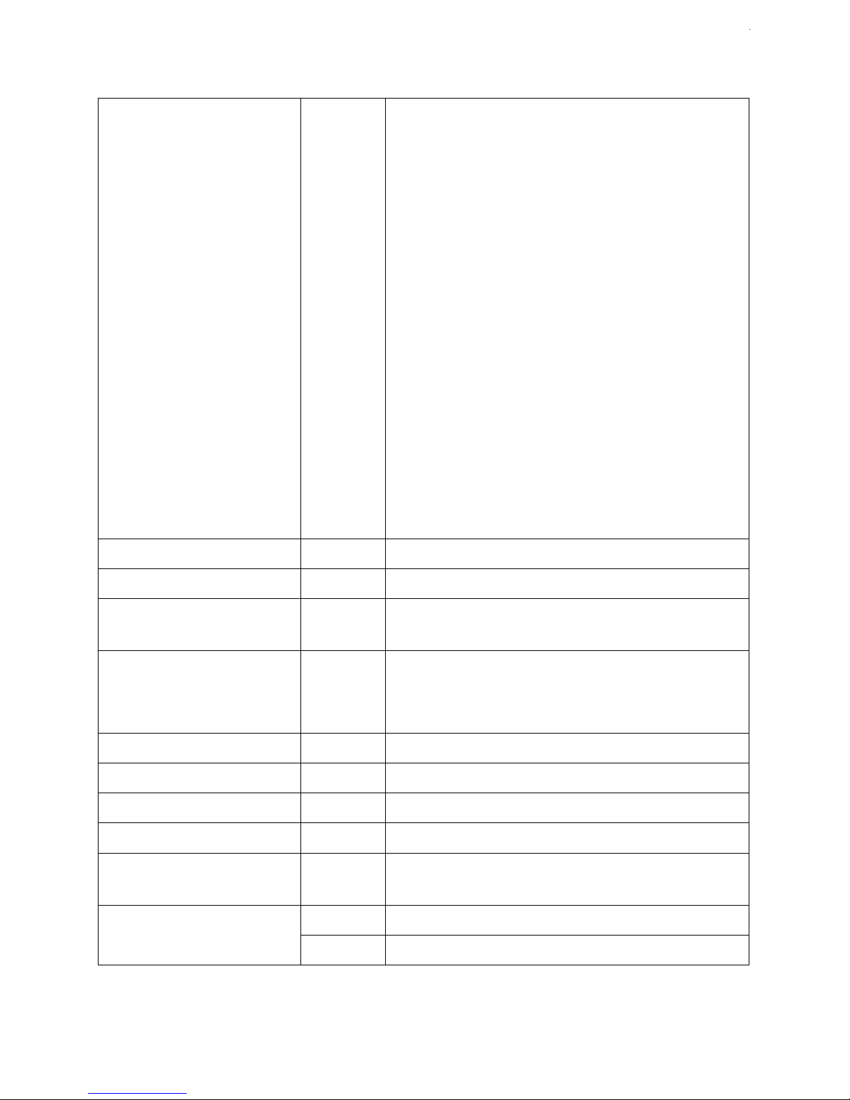
Fault Diagnosis
No Water
Dispenses
Pr
obl
em/
Report
Possible Cause
Suggested Action
No Water
Dispenses
From
Ambient
Valve
Water Supply
turned
off
Check all
T
a
ps/v
al
v
e
s/
filters
on
incoming
supply are fitted and are
turned on.
No
Electricity/Power Suppl
y
Check power cord
connected
and live
and
machine
is
switched on.
“Waterblock” tripped off
Reset “Waterblock” ( and check for cause
of leakage)
Faulty dispense control panel
membrane switch
Check and replace if required
Faulty Solenoid
V
a
l
v
e
V
a
l
v
e
clicking but no
water-Check
if hole in
centre
of
washer
is
cl
ea
r
.
Check valve action. Carefully
dismantle
v
a
l
v
e
and clean out
/part replace/complete
r
eplac
e
as
needed.
V
a
l
v
e
not
clicking-Check
voltage
output
when
operated.
If
no output
replace PCB.
If
there is output, replace
solenoid coil/whole
valve
coil/whole valve
as
sembl
y
c
ompl
e
te.
Leak
detector
has
disabled
dispense operation.
Check for
internal leakage, ensure probes
are
dry and
r
eset.
From Cold
V
a
l
v
e
Fir
s
tl
y
all as for
Ambient
Ta
p
Carry out
checks
and
actions
as for
ambient
tap.
Chiller tank frozen
-
F
aulty
Thermos
tat/Incorrect Setting
Thaw out, check and
replace
thermostat or reset
temperature
set
point.
Chiller tank F
r
ozen-faulty
air
pump
Thaw out, check
operation
and
replace
Air
pump
id necessary.

Boste BK Series
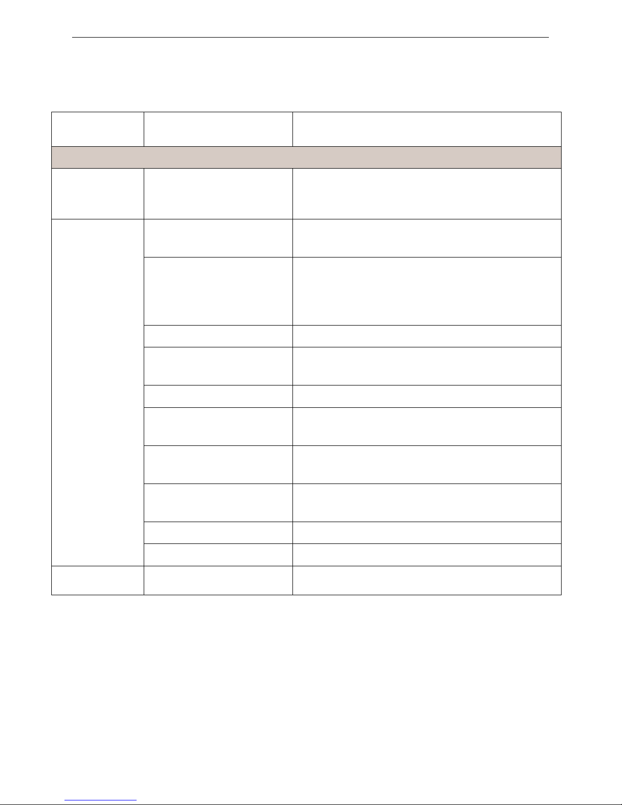
11
No Water
Dispenses continued
No Water
Dispenses
continued
From
Ambient
or Cold
V
a
l
v
e
Button not being
pr
es
sed
enough
Press
button firmly
Faulty c o ntr ol s P C B –no
v ol tag e ou tpu t .
Replace PCB –Check for 24 VDC outputs if necessary.
From
Sparkling
Valve
Carbonation System switched
off.
Check switch on back of the machine
Fir
s
tl
y
as for Ambient
and
or Cold
Dispense
Carry out the
checks
and
actions
as
f
o
r
Ambient
Dispense
Low or no CO2 pressure.
Check and
replace
cylinder as
nec
e
s
sary
Pump not
oper
ating
Check
carbonator
level Control Sys
tem.
Check
probes connected/leads attached.
Check
power supply to
pump.
Carbonator Tank over
pressurised with CO2
Switch Sparkling System off, shut off CO2 supply and
release CO2 from carbonator. Switch Sparkling system on,
then check pump operation.
If normal, open CO2 supply after pump has stopped.
Pump Feed Valve not opening
Check valve function:
If no input DC voltage, check rectifier and level control
module.
If input but no function, check valve coil.
Replace parts as needed.
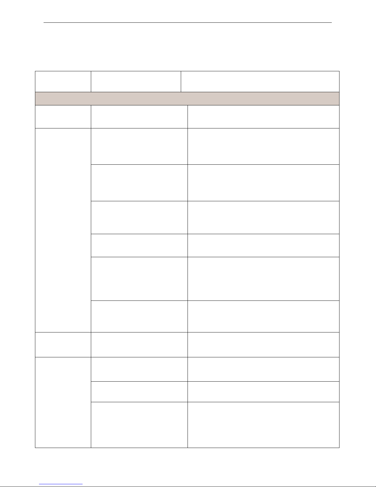
Boste BK Series
12
Water Dispenses but not correct Temperature
Pr
obl
em/
Report
Possible Cause
Suggested Action
Water
Dispenses
But Not Correct
T
emper
atur
e
Ambient
W
ater
too warm
Low
usage
and / or fed
from
water supply pipe in
warm
ducting.
Advise
user replacing
e
x
ternal
causes and
solutions.
Cold water
not
Cold
Cooling and or
Sparkling
System switched
off.
Check switch
positions on the back of the machine as
nec
e
s
sary
.
Compressor
runs and
switching off
(cool/warm to
touch) -
Thermostat
set
too
high.
Decrease
Cold
Thermostat
set
point.
Faulty
Thermos
tat.
Replace Thermos
tat
Compressor
runs but
not
Switching off (Hot to
touch).
Contact Aftersales Support.
Refrigeration
pr
obl
e
m.
Contact Aftersales Support.
Compressor
not
running
at
all.
Check voltage path through the machine.
No electricity power
suppl
y
.
Check power cord
connected
and live,
and
machine
is
switched on.
Compressor
only
hums
slightly/
briefl
y
.
Check and
replace
r
e
lays.
Relays l
oose.
Check and refit
r
e
lays.
Compressor
F
aulty.
Contact Aftersales Support.
DC Tank Empty
Check water level and replace level control module in
fill valve as needed.
Boste BK Series
13
Water Leaks
Pr
obl
em/
Report
Possible Cause
Suggested Action
Water
Leaks
Water lying
on
top edge of
lower
door
panel and /
or
bottom of
Cabinet.
Overflowing Waste Container
.
Empty Waste Container and check drain pipe is not
blocked.
Water lying in
bottom of
machine
Faulty W a ter S y s te m Level
Sensor.
Check
operation and replace batteries if needed.
Leak in supply inlet
pipe-
work and / or filte
r
.
Locate and
repair acc
o
r
dingl
y
.
Leak from
machine water
pipe work
fittings.
Locate and
repair acc
o
r
dingl
y
.
Check
pressure
and fit
pressure
r
educing
valve if
needed.
DC tank over overfilling
Check level control module and fill valve function.
Boste BK Series
14
Miscellaneous
Pr
obl
em/
Report
Possible Cause
Suggested Action
Misc
ellaneous
Bleeping
Noise
Waste Container full/Internal
water leak.(If fitted)
Empty Waste Container. Check and
reset Leak Detector.
No
LED function
Lights
No electricity to
Machine.
Check power supply and
reconnect
as
necessary
(Also check out other
symptoms
as
described
separa
tel
y).
Check Fuse in
IEC
Sock
et.
Replace
if
nec
e
s
sary
.
Faulty C o n tr o l PCB
(Machine working
normall
y
otherwise).
Replace Control PCB.
Machine
shak
es
on
Start-Up
Compressor Starting.
Level
Surf
a
c
e
.
No action
needed.
This is quite
normal.
Uneven
Surf
a
c
e
.
Level up
machine
using adjustable feet.
Missing Fixings.
Replace missing fixings.
Tripping
out
El
ectricity
suppl
y
Machine in high humidity
envir
onment.
Discuss possible repositioning with
cust
ome
r
.
Electrical
circuitry
f
aults.
T
e
s
t,
identify and
address
acc
o
r
dingl
y
.
See
Electrical Diagr
ams.
(Contact Azure Aftersales for
further
advice).

Boste BK Series
15
Miscellaneous continued
Pr
obl
em/
Report
Possible Cause
Suggested Action
Slow but Continuous Water
Dispense
From
Ambient
or Cold
W
ater
Valve
Low incoming
W
ater
pr
es
sur
e.
Consider re-plumbing to
alternative suppl
y
if
pos
s
ibl
e or boosting the inlet supply
pressure.
From
Sparkling
Water Valve
Low/no CO2
Pr
es
sur
e.
Check
Regulator
and/ or
replace
cylinde
r
.
Intermittent Water
Dispense
From
Ambient
or Cold
W
ater
Valve
Trapped air in pipe
w
o
rk
(especially where water
pressure
is low or
after
filter
change).
Hold button on to purge air out. (This
c
ould
take
se
v
e
r
al
minutes
where pressure
is low).
Use filter function if available.
Button Not being
pr
es
sed
enough.
Press
button firmly N.B. This could
be
caused
by a
surrounding
cold
envir
onment
making the action
s
tiff
e
r
.
Faulty C o n tr o l PCB
Replace Control PCB.
From
Ambient
or Cold
W
ater
V
a
l
v
e
and
hammering
noise
Fluctuating
mains water
pressure situation.
Contact Azure r
egar
ding
special
replacement washers
av
ailabl
e
.
Continuous Water
Dispense
From
Ambient/
Cold
or
Sparkling
Water Valve.
Button
jammed
on/faulty.
Replace Control
PCB and or/ button Panel as
needed.
Debris blocking hole in
diaphragm washe
r
.
Dismantle
V
a
l
v
e
and clean out
.
Faulty solenoid valve.
Check valve and replace if needed.
Boste BK Series
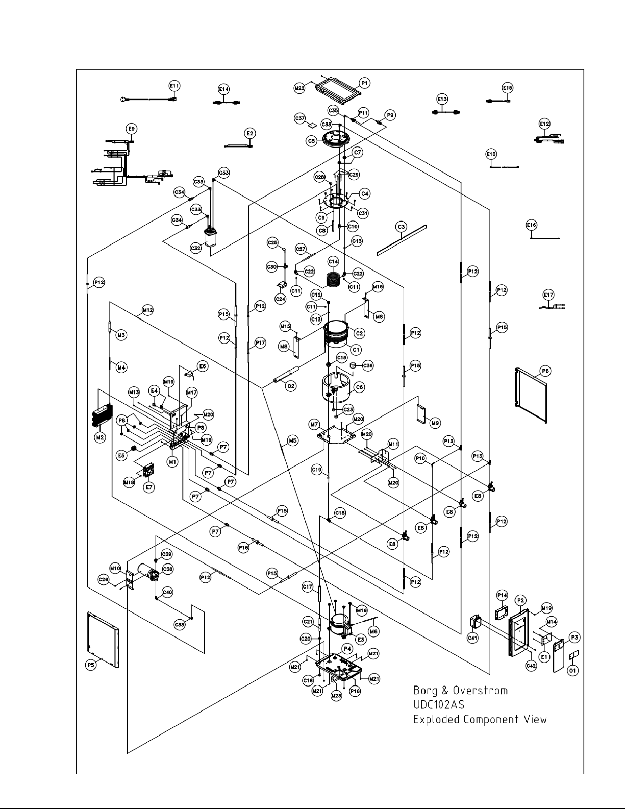
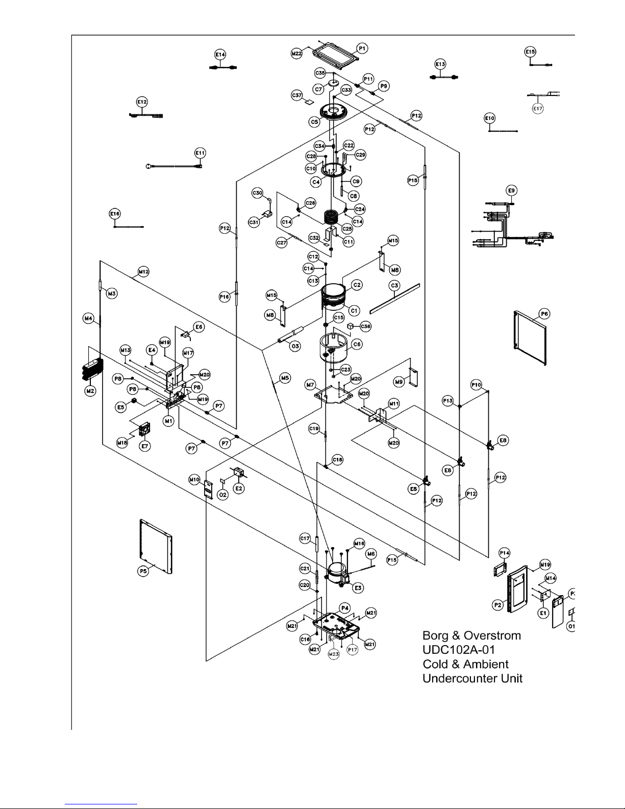
16
Diagrams & Parts Lists
17

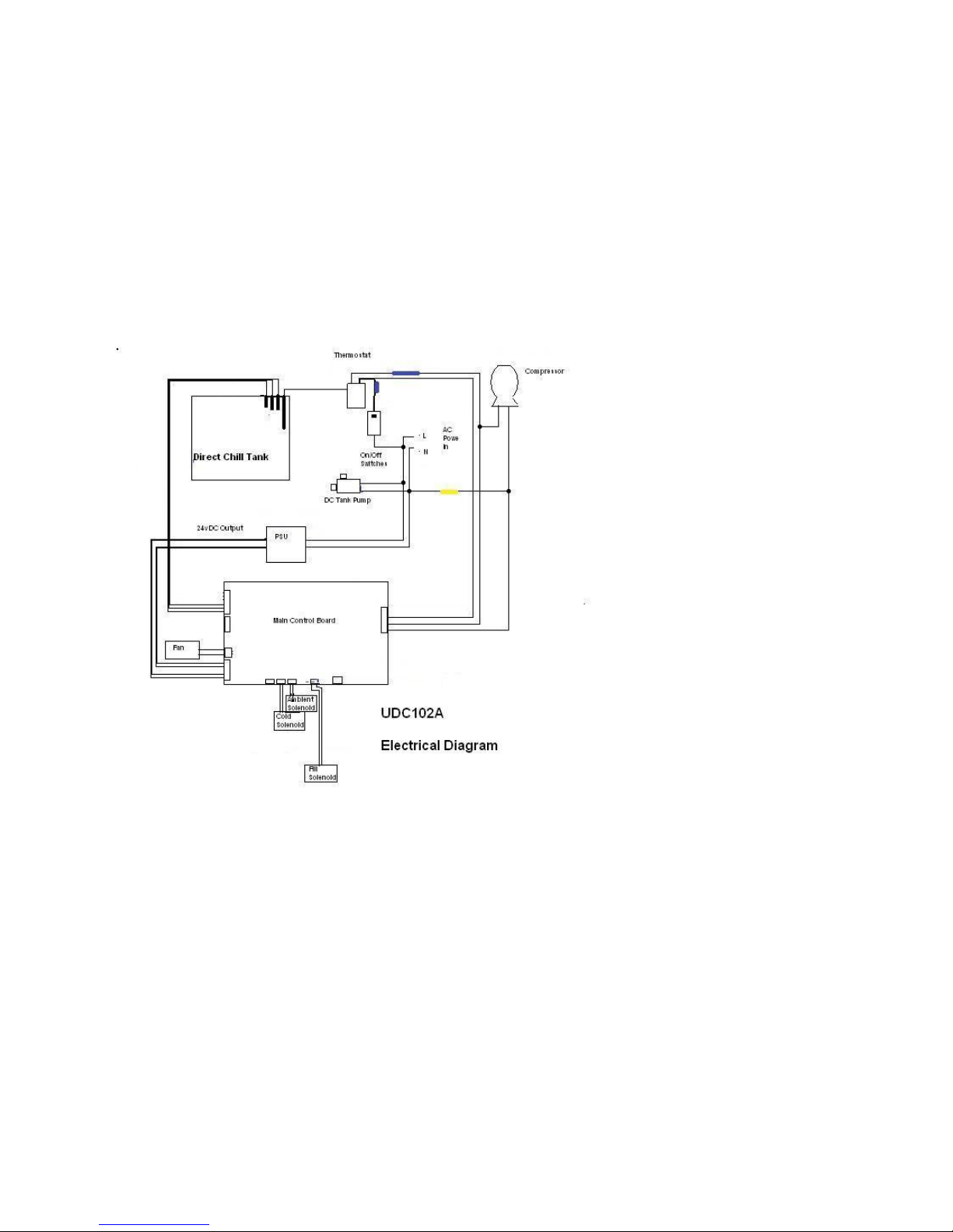
Table of contents
Popular Water Dispenser manuals by other brands


Bartscher
Bartscher 190990 instruction manual

Greenway Home Products
Greenway Home Products GWD5500WBC Use & care guide

Katadyn
Katadyn Siphon operating instructions

Follett
Follett 7UC100A Installation, operation and service manual

Stalgast
Stalgast DVA LT Series Instruction leaflet

Elkay
Elkay LZTL Series Installation, care & use manual