Bostitch BTMT72393 User manual

70101339 13/06 BOSTITCH AIRTOOL SYSTEMS
BEFORE OPERATING THIS TOOL, ALL OPERATORS SHOULD STUDY THIS
MANUAL TO UNDERSTAND AND FOLLOW THE SAFETY WARNINGS AND
INSTRUCTIONS. KEEP THESE INSTRUCTIONS WITH THE TOOL FOR FUTURE
REFERENCE. IF YOU HAVE ANY QUESTIONS, CONTACT YOUR STANLEY-
BOSTITCH REPRESENTATIVE OR DISTRIBUTOR.
ANTES DE OPERAR ESTA HERRAMIENTA, TODOS LOS OPERADORES
DEBERÁN ESTUDIAR ESTE MANUAL PARA PODER COMPRENDER Y
SEGUIR LAS ADVERTENCIAS SOBRE SEGURIDAD Y LAS INSTRUCCIONES.
MANTENGA ESTAS INSTRUCCIONES CON LA HERRAMIENTA PARA
FUTURA REFERENCIA, SI TIENE ALGUNA DUDA, COMUNÍQUESE CON SU
REPRESENTANTE DE STANLEY-BOSTITCH O CON SU DISTRIBUIDOR.
LIRE ATTENTIVEMENT LE PRÉSENT MANUEL AVANT D’UTILISER L’APPAREIL.
PRÉTER UNE ATTENTION TOUTE PARTICULIÈRE AUX CONSIGNES DE
SÉCURITÉ ET AUX AVERTISSEMENTS. GARDER CE MANUEL AVEC L’OUTIL
POUR FUTUR RÉFÉRENCE. SI VOUS AVEZ DES QUESTIONS, CONTACTEZ
VOTRE REPRÉSENTANT OU VOTRE CONCESSIONNAIRE STANLEY-BOSTITCH.
OPERATION AND MAINTENANCE MANUAL
MANUAL DE OPERACIÓNY DE MANTENIMIENTO
MANUEL D’INSTRUCTIONS ET D’ENTRETIEN
BTMT72393
GRAVITY FEED HVLP SPRAY GUN
PISTOLA ASPERSORA DE ALIMENTACIÓN POR
GRAVEDAD DE ALTO VOLUMENY BAJA PRESIÓN (HVLP)
PISTOLET HVP À GRAVITATION

INTRODUCTION
• Fastworking speed and wide fan pattern.
• High transfer efcency means reduced spray mist.
• Stainless steel needle and uid tip allow use with Water borne materials.
• Maximum Operating Pressure: 50 psi
• High efciency design signicantly reduces operating costs.
INDEX
3 Year Limited Warranty .............................................................2
Tool Components, Tool Specications...................................... 3
Important Safety Instructions ................................................... 4
Warning ...................................................................................... 5
Installation ..................................................................................6
Operation ....................................................................................7
Maintenance ...............................................................................8
Trouble Shooting Guide ............................................................ 9-10
IMPORTANT
Please make certain that person who is to use this equipment carefully reads and understands these
instructions before operating.
3YEAR LIMITED WARRANTY — U.S. and Canada Only
Stanley warrants this product to the original purchaser for a period of THREE (3) YEARS against
deciencies in material and workmanship. This LIMITED WARRANTY does not cover products that are
improperly used, abused, altered or repaired. Decient products will be replaced or repaired at Stanley's
option. Please call 1-800-505-4648 for more information or return instructions.
THIS LIMITED WARRANTY IS GIVEN IN LIEU OF ALL OTHERS INCLUDING THE IMPLIED WARRANTY OF
MERCHANTABILITY AND FITNESS FOR A PARTICULAR PURPOSE AND EXCLUDES ALL INCIDENTAL OR
CONSEQUENTIAL DAMAGES. Some states do not allow limitations on how long an implied warranty
lasts or the exclusion or limitation of incidental or consequential damages, so these limitations may not
apply to you. This LIMITED WARRANTY gives you specic legal rights that may vary from state to state.
SAFETY GUIDELINES - DEFINITIONS
This manual contains information that is important for you to know and understand. This information
relates to protecting YOUR SAFETY and PREVENTING EQUIPMENT PROBLEMS. To help you recognize this
information, we use the symbols below. Please read the manual and pay attention to these sections.
SAFETY and PREVENTING EQUIPMENT PROBLEMS.To help you recognize this information, we
use the symbols below. Please read the manual and pay attention to these sections.
Indicates an imminently
hazardous situation which,
if not avoided, will result in death or serious
injury.
Indicates a potentially
hazardous situation which,
if not avoided, may result in minor or
moderate injury.
Indicates a potentially
hazardous situation which,
if not avoided, could result in
death or serious injury.
Used without the
safety alert symbol indicates a
potentially hazardous situation which,
if not avoided, may result in property damage.
- 2 -

- 3 -
FIG.1
TOOL COMPONENTS
BTMT72393
Description Gravity Feed Hvlp Spray Gun
Average Air Consumption 5.6CFM 100% Usage
Fluid output 170cc/min
Air Inlet 1/4" NPS (F)
Weight 0.7095KG (1.56lbs)
Min. Hose Size 3/8" ID
Required PSI 30-50 psi
Fluid inlet 3/8" NPS
Inlet Air Pressure 50 psi
Pattern Width > 180mm
NozzleTip 1.5mm
Air connection 1/4'NPT (M)
Air Valve Nut
Fluid Control
Knob
Air Volume Control
Knob
Spray Pattern
Adjustment
Non-Drip Cup
TOOL SPECIFICATIONS
All dimensions in inches unless otherwise specified.
Material Filter
Horns
Air Cap

- 4 -
Definitions: Safety Guidelines
The definitions below describe the level of severity
for each signal word. Please read the manual and pay
attention to these symbols.
DANGER: Indicates an imminently hazardous
situation which, if not avoided, will result in death or
serious injury.
WARNING: Indicates a potentially hazardous
situation which, if not avoided, could result in death
or serious injury.
CAUTION: Indicates a potentially hazardous
situation which, if not avoided, may result in minor
or moderate injury.
CAUTION: Used without the safety alert symbol indi-
cates a potentially hazardous situation which, if not
avoided, may result in property damage.
IMPORTANT SAFETY INSTRUCTIONS
Some dust created by power
sanding, sawing, grinding, drilling,
and other construction activities contains chemicals
known to the State of California to cause cancer,
birth defects or other reproductive harm. Some
example of these chemicals are:
• Lead from lead-based paints
• Crystalline silica from bricks and cement
and other masonry products
• Arsenic and chromium from chemically-treated
lumber
Your risk from these exposures varies, depending on
how often you do this type of work. To reduce your
exposure to these chemicals: work in a well ventilat-
ed area, and work with approved safety equipment,
al ways wear OSHA/MSHA/NIOSH approved,
properly fit ting face mask or res pi ra tor when us ing
such tools.When using air tools, basic safety precau-
tions should always be followed to reduce the risk of
personal injury.
This product contains chemicals,
known to the State of California to cause cancer,
and birth defects or other reproductive harm.Wash
hands after handling.
SAVETHESE INSTRUCTIONS
Improper operation or maintenance of
this product could result in serious injury
and property damage. Read and
understand all warnings and operating
instructions before using this equipment.
When using air tools, basic safety precautions
should always be followed to reduce the risk of
personal injury.
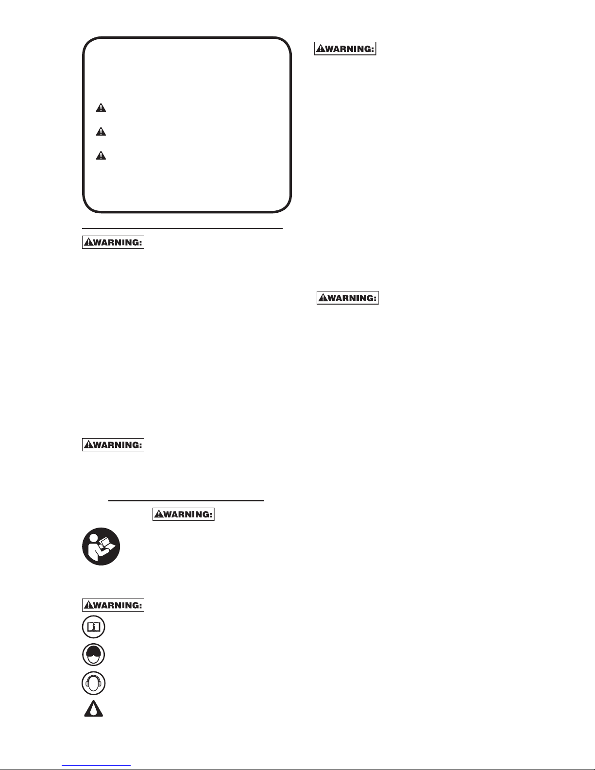
Read and understand this instruction manual
and tool labels before installing, operating or
servicing this tool. Keep these instructions in
a safe accessible place.
Operators and others in work area must wear
ANSI Z87.1 CAN/CSA Z94.3 approved safety
glasses with side shields.
Operators and others in work area must wear
ear protection.
Oil daily for optimal performance.
• All persons in the work area must always
wear approved eye and hearing protection
and approved respiratory protection when this
spray gun is in operation.
• Never aim spray gun at anyone. Do not spray
near sparks, open flame, lit cigarettes, pilot
lights, space heaters or any other potential
ignition source, DO NOT SMOKE IN WORK
AREA.
• Only persons well acquainted with these rules
of safe operation should be allowed to use the
air tool .
• Follow manufacturers instructions and safety
information to ensure safe handling and proper
use of paints, laquers, thinners, base coats, etc.
Do not use latex or other heavy paints. They are
not recommended for this spray gun.
• Always keep work area free from obstructions
and well ventiilated.
• Always disconnect spray gun from air source
before disassembly.
• To avoid creating an explosive atmosphere,
work only in well ventilated areas.
• Always use respiratory protection to prevent
inhalation of harmful fumes and materials.
• Before disassembly or removal of any part of
gun or attached components, shut off
compressor, release pressure by depressing
trigger, and disconnect power source. NEVER
assume system pressure is zero!

- 5 -
RISK OF EXPLOSION OR FIRE
WHAT CAN HAPPEN HOWTO PREVENT IT
• When paints or
materials are
sprayed, they are
broken into very
small particles and
mi xed with air. This
will cause certain
paints and
materials to
become extremely
flammable and
could result in
serious
injury or death.
• Never spray near
open flames or pilot
lights in stoves or
heaters.
• Never smoke while
spraying.
• Provide ample
ventilation when
spraying indoors.
• 1,1,1-Trichloroethane
and Methylene
Chloride can
chemically react
with the aluminum
used in most spray
equipment, and
this gun and cup,
to produce an
explosion hazard
and could result
in serous injury or
death.
• Read the label or
data sheet for the
material you intend
to spray.
• Never use any type
of spray coating
material containing
these solvents.
• Never use these
solvents for
equipment cleaning
or flushing.
• If in doubt as to
whether a material
is compatible,
contact your
material supplier.
RISK TO BREATHING
(ASPHYXIATION)
WHAT CAN HAPPEN HOWTO PREVENT IT
• Some paints,
coatings and
solvents may cause
lung damage, and
burns if inhaled or
allowed to come
into contact with
skin or eyes.
• Use a NIOSH
approved mask
or respirator and
protective cloth-
ing designed for
use with your
specific application
and spray materi-
als. Some masks
provide only limited
protection against
toxic materials and
harmful paint sol-
vent. Consult with
a Safety Expert or
Industrial Hygienist
if uncertain about
your equipment or
materials.
RISK OF CUT OR BURNS
WHAT CAN HAPPEN HOWTO PREVENT IT
• Spray guns
operate at
pressures and
velocities high
enough to
penetrate human
and animal flesh,
which could result
in amputation or
other serious injury.
! See a physician
immediately !
• Never place hands
in front of nozzle.
• Direct spray away
from self and
others.
• Seek immediate
medical attention if
direct spray
contacts
exposed body
parts.
RISK FROM FLYING OBJECTS
WHAT CAN HAPPEN HOWTO PREVENT IT
• Certain parts are
under pressure
whenever the gun
is connected to
a pressurized air
line. These parts
may be propelled
if the gun is disas-
sembled.
• Disconnect the
gun from the air
line, or completely
depressurize the
air line whenever
the gun is to
be disassembled.
• Compressed air
may propel dirt,
metal shavings,
etc. and possibly
cause an injury.
• Never point any
nozzle or sprayer
toward a person or
part of the body.
• Always wear ANSI
Z87.1 CAN/CSA
Z94.3 approved
safety glasses with
side shields.
• Prolonged expo-
sure to air spray
can result in
permanent dam-
age to hearing.
• Always wear hear-
ing protection
when operating
spray equipment.

INSTALLATION
AIR SUPPLY
The recommended hook-up is shown in Figure A. Pneumatic tools operate on a wide range of air
pressures. For maximum efficiency and longer tool life, the pressure of the air supplied to these tools MUST not
exceed the rated PSI at the tool when the tool is running. Using a higher than rated pressure will cause faster
wear and drastically shorten the tool’s life. A higher air pressure can also cause an unsafe condition and explo-
sion. The inside diameter of the hose should be increased to compensate for unusually long air hoses (over 25
feet). Minimum hose diameter should be 3/8” I.D. and fittings should have 1/4” NPT thread. The use of air line
lubricators and air line filters is recommended to prevent water in the line that can damage the tool. Drain the
air tank daily. Clean the air inlet filter screen on at least a weekly schedule to remove accumulated dirt or other
matter that can restrict air flow. The tool’s air inlet used for connecting an air supply has standard 1/4” NPT
American thread.
SAFETY RULES FOR PNEUMATIC TOOLS
1) Inspect the air hose for cracks or other problems. Replace the hose if worn.
2) Never point an air hose at another person.
3) Disconnect the tool when not in use, or before performing service or changing accessories.
4) Use proper hoses and fittings. Never use quick change couplings attached to the tool. Instead, add a hose and
coupling between the tool and the air supply.
FIGURE A
- 6 -
1/2”(or larger)
Pipe and Fittings
Coupler
Air Hose
Leader Hose
Tool
Nipple
Oiler Filter
Drain Daily

OPERATION
DO NOT ATTEMPTTO UNCLOG (BACK
FLUSH) SPRAY GUN BY SQUEEZING
TRIGGER WHILE HOLDING FINGER IN FRONT OF FLUID
NOZZLE.
PRESSURE MAY VARY ACCORDING
TO VISCOSITY OF MATERIAL USED.
MAXIMUM WORKING PRESSURE OF GUN IS 50 PSI.
DO NOT EXCEED PRESSURE LIMIT OF GUN OR ANY
OTHER COMPONENT IN SYSTEM!
PRIOR TO DAILY OPERATION, MAKE
CERTAIN THAT ALL CONNECTIONS
AND FITTINGS ARE SECURE. CHECK HOSE AND ALL
CONNECTIONS FOR A WEAK OR WORN CONDITION
THAT COULD RENDER SYSTEM UNSAFE. ALL
REPLACEMENT COMPONENTS SUCH AS HOSE
OR FITTINGS MUST HAVE A WORKING PRESSURE
EQUAL TO OR GREATER THAN SYSTEM PRESSURE.
Prior to shipment, this gun was treated with an
anticorrosive agent. Before using this gun make sure
that it is carefully ushed with thinner.
1. The position of the air cap (H) horns will determine
the spray pattern. Loosen (G) air cap and rotate horns
to achieve desired pattern. Tighten air cap.
2. Attach paint cup to the gun.
NOTE: The (F) filter supplied is optional to protect
against contaminants and small particles. See parts
list for lter orientation.
3. Attach air supply line to 1/4 NPS air inlet.
NEVER point spray gun at self or any other person.
Accidental discharge of material may result in serious injury.
4. Adjust air pressure at air compressor.
DO NOT exceed 50 psi.
5. Depress spray gun trigger fully to spray material.
NOTE: Depressing trigger partially will cause only air to be released.
ADJUST SPRAY GUN:
a. Amount of material released (density of “fan spray”) is controlled
by (D) fluid control knob . Turn knob counterclockwise to increase, or
clockwise to decrease, the uid ow.
b. Width of “fan spray” is governed by (B) spray pattern control knob. Turn knob counter-clockwise to
increase, or clockwise to decrease, air ow.
c. Air quantity is controlled by (C) air-volume control knob. Turn knob counterclockwise to increase, or
clockwise to decrease, the air ow.
NOTE: Care should be exercised when handling spray gun to avoid damage to the orice of the air cap
and tip of uid nozzle. Damage to these parts results in irregular spray patterns.
- 7 -
(A) Air
Valve Nut
(E) Non-Drip Cup
(G) Air Cap
(C) Air
Volume
Control Knob
(D) Fluid
Control
Knob
(B) Spray
Pattern
Adjustment
(H) Horns
(F) Material
Filter
Horizontal position
Vertical position

- 8 -
MAINTENANCE
SHUT OFF AIR COMPRESSOR, RELEASE ALL PRESSURE BY DEPRESSING TRIGGER, AND
DISCONNECT POWER SOURCE BEFORE DISASSEMBLY OR REMOVAL OF ANY PART OFTHE GUN OR
ATTACHED COMPONENTS.
ALWAYS EXERCISE EXTREME CARE WHEN USING ANY SOLVENT ORTHINNER. NEVER
CLEANTHE GUN NEAR FIRE, FLAME, OR ANY SOURCE OF HEAT OR SPARKS. PROPERLY DISPOSE OF
USED CLEANING MATERIALS.
DO NOT SOAKTHE ENTIRE SPRAY GUN IN SOLVENT ORTHINNER FOR A LONG PERIOD
OFTIME ASTHIS WILL DESTROY LUBRICANTS AND POSSIBLY IMPAIR OPERATION. NEVER USE LYE OR
CAUSTIC ALKALINE SOLUTION FOR CLEANING. SUCH SOLUTIONSWILL ATTACK ALUMINUM ALLOY
PARTS OFTHE GUN.
It is important that the spray gun be cleaned after each use.
CLEANING
1. Empty material from gravity feed cup and replace with a suitable solvent or thinner.
2. Operate trigger until all material traces have disappeared and gun is thoroughly clean.
3. Clean air cap with a brush.
4. Wipe the exterior of the spray gun with a solvent soaked cloth or use cleaning brush(es) provided to
remove any accumulated material.
IMPORTANT: Make certain that the air cap and uid nozzle are kept clean at all times. If necessary, remove
these two components and soak them in solvent. DO NOT use hard objects to clean clogged holes. The
smallest amount of damage may cause
irregular spray pattern.
NOTE: If the uid nozzle is to be removed for thorough cleaning, squeeze the trigger to prevent damage of
the uid needle tip when unscrewing the nozzle.
LUBRICATION
Lubrication procedures must be observed after thoroughly cleaning the gun to ensure effective, high
quality performance of spray gun.
1. Lubricate working points with straight mineral oil, or castor oil.
2. Periodically, place a few drops of oil on tapered sections of the uid nozzle to ensure easy operation
of the air cap. When spraying water base materials, coat the uid nozzle inside and outside with straight
mineral oil after each use.
3. Outer diameter of the needle sleeve in the uid needle assembly must be lubricated occasionally with
straight mineral oil.

- 9 -
TROUBLESHOOTING GUIDE
This section provides a list of the more frequently encountered malfunctions, their cause and corrective
actions. The operator or maintenance personnel can perform some corrective actions, and others may
require the assistance of a qualied Bostitch technician or your dealer.
DEFECTIVE PATTERN LIKELY CAUSE SUGGESTED REMEDY
HEAVY TOP OR
BOTTOM PATTERN 1. Dirty or damaged
air cap
2. Dirty or damaged
uid tip
1. Rotate air cap 180°. If the
pattern follows the air cap,
the problem is in the air cap.
Clean and inspect the air cap.
If the pattern is not corrected,
replacement is necessary.
2. If pattern doesn’t follow the
air cap, the problem is with
the uid tip. Clean and
inspect the tip for dried paint,
dirt or damage. If the pattern
is not corrected, replacement
is necessary.
SPLIT PATTERN Air pressure too high for
material viscosity being sprayed. 1. Reduce air pressure.
2. Turn pattern control knob
clockwise to decrease fan
width. Turn uid needle
adjusting nut counterclockwise
to increase uid ow.
1. Dirty or distorted air horn
holes.
2. One of the air horn holes
completely obstructed.
1. Rotate air cap 180°. If the
pattern follows the air cap,
the problem is in the air cap.
2. Clean and inspect the horn
holes. If the horn holes are
distorted, replacement is
necessary.
GUN SPLITTING Air getting into paint stream
somewhere.
Example: Same symptoms as a
cup running out paint.
1. Check and tighten uid needle
packing nut.
2. Tighten uid tip.
3. Check uid tip seat for
damage.
4. Check for poor gun to cup
seating.
5. Check that cup is correctly
fastened on the gun.
SPITTING, IRREQULAR
OR FLUTTERING SPRAY 1. Fluid nozzle
cracked or worn
2. Leak at thread
of uid nozzle
3. Leak at uid needle
4. Needle packing
worn out
5. Insufcient uid in cup
6. Vent hole in
container cover clogged
1. Tighten or replace
2. Tighten uid nozzle
3. Tighten compression nut
assembly or replace needle
packing
4. Replace packing
5. Fill cup with uid
6. Clean out
AIR BACK
PRESSURING
INTO CUP.
Excessive air blowing back into
cup. 1. Tighten uid tip.
2. Check uid tip seat.
3. Check for damaged uid seat
on tip or seat on gun head.

- 10 -
TROUBLESHOOTING GUIDE:
This section provides a list of the more frequently encountered malfunctions, their cause and corrective
actions. The operator or maintenance personnel can perform some corrective actions, and others may
require the assistance of a qualied Bostitch technician or your dealer.
DEFECTIVE PATTERN LIKELY CAUSE SUGGESTED REMEDY
UNATOMIZED
OR SPATTERED
SPRAY
1. Material too heavy
2. Insufcient air
pressure
3. Fluid pressure
too high
4. Dried material on tip
of uid nozzle or
air jets of air cap
1. Thin material or use larger
orice uid nozzle set
2. Increase pressure to within
limit
3. Reduce pressure
4. Clean
INADEQUATE
AIR DELIVERY 1. Air needle partially
closed
2. Dried material in air
jets or air cap
3. Obstruction in air line.
1. Open control knob
2. Clean
3. Remove obstruction
EXCESSIVE FOG 1. Air pressure too high
for viscosity of uid 1. Reduce air pressure and/or
open uid control knob
MATERIAL LEAKING
FROM FLUID INLET
OF CUP
1. Loose cup or foreign
substances on/between cup
thread and uid inlet
1. Tighten and clean or replace it
MATERIAL LEAKING
FROM NOZZLE WHEN
TRIGGER IS RELEASED
1. Worn uid neddle
2. Dried material in tip of nozzle
3. Loose packing nut
1. Replace
2. Clean
3. Tighten needle packing nut by
turning counterclockwise
A. Dried material is
clogging side-port “A”
and causing
side-port “B” to blow
spray towards the
clogged side
Soak side-ports in
thinner to clean clog.
DO NOT poke any
opening with hard objects.
B. 1. Dried material at
uid nozzle “C”
restricts air ow
2. Loose air nozzle
3. Air pressure
set too high
1. Remove air nozzle.
Wipe off uid tip using a
cloth soaked in thinner
or by soft brush
2. Fasten nozzle securely
3. Reduce air pressure
A
B
C

- 11 -
GLOSSARY
CFM: Cubic feet per minute.
SCFM: Standard cubic feet per minute; a unit of measure of air delivery.
PSI: Pounds per square inch; a unit of measure of pressure.
Code Certification: Products that bear one or more of the following marks: UL, CUL, ETL, CETL, have
been evaluated by OSHA certied independent safety laboratories and meet the applicable Underwriters
Laboratories Standards for Safety.
RPM: Revolutions per minute; is a measure of the frequency of a rotation
BPM: Beats per minute.
NPT: National pipe thread (tapered thread); is a U.S. standard for tapered threads used on threaded
pipes and ttings.
ID: Inner diameter
LAS CAÍDAS PUEDEN CAUSAR
LESIONES GRAVES. NO PISAR NI
PARARSE EN ESTA ÁREA.
ADVERTENCIA
LES CHUTES PEUVENT CAUSER DE GRAVES
BLESSURES. NE MARCHEZ PAS ET NE VOUS
TENEZ PAS SUR CET EMPLACEMENT.
AVERTISSEMENT
FALLS CAN CAUSE SERIOUS
INJURIES. DO NOT STEP OR STAND
ON THIS AREA.
WARNING
SEE OWNER’S MANUAL FOR
BREAK-IN PROCEDURES.
CAUTION
PARA EL PROCEDIMIENTO DE
ASENTADO DE LA MAQUINA, VER
MANUAL DEL OPERARIO.
ATENCIÓN
CONSULTEZ LE MANUEL DE
L’UTILISATEUR POUR LES
PROCEDURES DE RODAGE.
ATTENTION
ADVERTENCIA
EL USO INDEBIDO PUEDE GENERAR RIESGOS. SEGUIR ESTAS INSTRUCCIONES: RIESGO DE ESTALLIDO. ASEGÚRESE QUE LA VÁLVULA DE SALIDA DEL
COMPRESOR ESTE REGULADA POR DEBAJO DEL MÁXIMO DE LA PRESIÓN DE OPERACIÓN DE LA PISTOLA ROCIADORA O HERRAMIENTA. ANTES DE ARRANCAR
EL COMPRESOR, TIRAR DEL ANILLO EN LA VÁLBULA DE SEGURIDAD PARA ASEGURARSE QUE LA VÁLVULA SE MUEVE LIBREMENTE. DRENAR EL AGUA DEL TANQUE DESPUÉS DE CADA USO.
RIESGO DE FUEGO O EXPLOSIÓN. NO ROCIAR LÍQUIDO NI PINTURAS INFLAMABLES O COMBUSTIBLES CERCA DE CHISPAS, LLAMAS, LLAMAS DE PILOTO O EN ÁREAS CERRADAS. EL ÂREA DE
TRABAJO DEBE ESTAR BIEN VENTILADA. MANTENER EL COMPRESOR ALEJADO POR LO MENOS 20 PIES DEL AREA DE PINTURA. NO LLEVAR NI OPERAR EL COMPRESOR NI DISPOSITIVO ELÉCTRICO
ALGUNO CERCA DEL AREA DEL ROCIADO. NUNCA FUME EN EL ÁREA DEL ROCIADO. USAR UNA MANGUERE DE UN MÍNIMO DE 25 PIES PARA CONECTAR LA PISTOLA AL COMPRESOR. RIESGO DE
DAÑOS PERSONALES. USAR GAFAS DE SEGURIDAD ANSI Z87. NUNCA APUNTAR EL CHORRO DE AIRE COMPRIMIDO O DE MATERIAL QUE SE ESTÉ ROCIANDO A SÍ MISMO NI A OTRAS PERSONAS.
NE RESPIRAR EL AIRE COMPRIMIDO. REDUCIR LA PRESIÓN A CERO ANTES DE DESMONTAR LA MANGUERA. RIESGO DE CHOQUE ELÉCTRICO. ALTO VOLTAJE. DESCONECTAR LA UNIDAD ANTES DE
QUITAR LA CUBIERTA. NO EXPONER A LLUVIA. ALMACENAR EN INTERIORES. PARA SEGURIDAD COMPLETA, OPERACIÓN E INSTRUCCIONES PARA REPARAR, LEER EL MANUAL DEL OPERADOR.
AVERTISSEMENT
UNE UTILISATION INCORRECTE PEUT ÊTRE DANGEREUSE. SUIVEZ LES INSTRUCTIONS CI-DESSOUS: RISQUE D'ECLATEMENT. ASSUREZ-VOUS QUE LA
PRESSION DE SORTIE DU COMPRESSEUR EST RÉGLÉE À UN NIVEAU INFÉRIEUR À LA PRESSION D'UTILISATION MAXIMUM DU PISTOLET VAPORISATEUR OU DE
L'ACCESSOIRE. AVANT DE DÉMARRER LE COMPRESSEUR, TIREZ SUR L'ANNEAU DE LA SOUPAPE DE SÛRETÉ POUR VOUS ASSURER QU'ELLE FONCTIONNE LIBREMENT. VIDANGEZ L'EAU DU RÉSERVOIR
À AIR APRÈS CHAQUE UTILISATION. RISQUE D'INCENDIE OU D'EXPLOSION. NE PAS VAPORISER UN LIQUIDE OU UN PEINTURE INFLAMMABLE OU COMBUSTIBLE PRÈS D'ÉTINCELLES, DE FLAMMES, DE
VEILLEUSES NI DANS UN ENDROIT RESTREINT OU RENFERMÉ. L'AIRE DE VAPORISATION DOIT ÊTRE BIEN AÉRÉE. GARDEZ LE COMPRESSEUR À UNE DISTANCE D'AU MOINS 20 PIEDS DE LA SURFACE À
VAPORISER. NE PORTEZ PAS LE COMPRESSEUR ET NE L'UTILISEZ PAS NI AUCUN AUTRE APPAREIL ÉLECTRIQUE À PROXIMITÉ DE L'AIRE DE VAPORISATION. NE FUMEZ JAMAIS QUAND VOUS
VAPORISEZ. UTILISEZ UN FLEXIBLE D'AIR D'UNE LONGUEUR MINIMUM DE 25 PIEDS POUR RELIER LE PISTOLET VAPORISATEUR AU COMPRESSEUR. RISQUE DE BLESSURES CORPORELLES. PORTEZ DES
LUNETTES DE PROTECTION ANSI Z87. NE DIRIGEZ JAMAIS L'AIR COMPRIME OU DES MATÉRIAUX VERS SOI OU VERS AUTRUI. NE JAMAIS UTILISER DE L'AIR COMPRIMÉ POUR LA RESPIRATION. RÉGLEZ
LA PRESSION À ZÉRO AVANT DE RETIRER LE BOYAU. RISQUE DE CHOC ÉLECTRIQUE. VOLTAGE DANGEREUX. DEBRANCHEZ LA MACHINE AVANT D'ENLEVER BOITIER. N'EXPOSEZ PAS LE COMPRESSEUR
À LA PLUIE. REMISEZ-LE À L'INTÉRIEUR. LISEZ LE MANUEL DE L'UTILISATEUR POUR DES INSTRUCTIONS COMPLÈTES CONCERNANT LA SÉCURITÉ, L'UTILISATION ET LES RÉPARATIONS.
INCORRECT USE CAN CAUSE HAZARDS. FOLLOW THESE INSTRUCTIONS: RISK OF BURSTING. MAKE SURE THE COMPRESSOR OUTLET PRESSURE IS SET
LOWER THAN THE MAXIMUM OPERATING PRESSURE OF THE SPRAY GUN OR TOOL. BEFORE STARTING THE COMPRESSOR, PULL THE RING ON THE SAFETY
VALVE TO MAKE SURE THE VALVE MOVES FREELY. DRAIN WATER FROM TANK AFTER EACH USE. RISK OF FIRE OR EXPLOSION. DO NOT SPRAY A FLAMMABLE OR COMBUSTIBLE
LIQUID OR PAINT NEAR SPARKS, FLAMES, PILOT LIGHTS, OR IN A CONFINED AREA. THE SPRAY AREA MUST BE WELL VENTILATED. KEEP COMPRESSOR AT LEAST 20 FEET AWAY FROM
SPRAY AREA. DO NOT CARRY AND OPERATE THE COMPRESSOR, OR ANY OTHER ELECTRICAL DEVICE NEAR THE SPRAY AREA. NEVER SMOKE WHEN SPRAYING. USE A MINIMUM OF
25 FEET OF HOSE TO CONNECT A SPRAY GUN TO THE COMPRESSOR. RISK OF PERSONAL INJURY. WEAR ANSI Z87 SAFETY GLASSES. NEVER SPRAY COMPRESSED AIR OR MATERIAL
AT SELF OR OTHERS. DO NOT USE COMPRESSED AIR FOR BREATHING. REGULATE PRESSURE TO ZERO BEFORE REMOVING HOSE. RISK OF ELECTRICAL SHOCK. HAZARDOUS VOLTAGE.
UNPLUG UNIT BEFORE REMOVING COVER. DO NOT EXPOSE TO RAIN, STORE INDOORS. READ OWNER'S MANUAL FOR COMPLETE SAFETY, OPERATION, AND REPAIR INSTRUCTIONS.
WARNING
HOLD HOSE FIRMLY TO
PREVENT HOSE WHIP.
CAUTION
SOSTENGA LA MANGUERA
CON FIRMEZA PARA EVITAR EL.
ATENCIÓN
BIEN TENIR LE TUYAU POUR
ÉVITER UN À-COUP.
ATTENTION
DRAIN TANK DAILY OR AFTER EACH USE. CONDENSATION BUILD-UP MAY CAUSE CORROSION
INSIDE TANK RESULTING IN TANK FAILURE. SEE MANUAL FOR INSPECTION PROCEDURES. TO DRAIN
TANK OPEN VALVE SLOWLY AND TILT COMPRESSOR TO EMPTY ACCUMULATED WATER.
WARNING
DRENE EL TANQUE A DIARIO O DESPUÉS DE CADA USO. LA ACUMULACIÓN DE CONDENSACIÓN
PUEDE OCASIONAR CORROSIÓN DENTRO DEL TANQUE Y PROVOCAR FALLA DEL TANQUE.
CONSULTE EL MANUAL PARA CONOCER LOS PROCEDIMIENTOS DE INSPECCIÓN. PARA DRENAR EL TANQUE, ABRA LA
VÁLVULA LENTAMENTE E INCLINE EL COMPRESOR PARAELIMINAR EL AGUA ACUMULADA.
ADVERTENCIA
RÉSERVOIR DE VIDANGE QUOTIDIEN
OU APRÈS CHAQUE UTILISATION. L'HABILLAGE
DE
CONDENSATION PEUT CAUSER LA CORROSION À L'INTÉRIEUR DU RÉSERVOIR AYANT POUR
RÉSULTAT L'ÉCHEC DE RÉSERVOIR. VOIR LE MANUEL POUR DES PROCÉDURES D'INSPECTION. À LA VALVE
OUVERTE
DE RÉSERVOIR DE VIDANGE LENTEMENT ET AU COMPRESSEUR D'INCLINAISON À L'EAU ACCUMULÉE VIDE.
AVERTISSEMENT

- 12 -
INTRODUCCIÓN
• Velocidad de rápido funcionamiento y modelo de ventilador ancho
• VEcacia de transferencia elevada signica pulverización reducida
• Aguja de acero inoxidable y tapa de uido que permite usar con materiales transportados por agua
• Presión máxima de funcionamiento: 50 psi
• Diseño de ecacia elevada que reduce signicativamente los costos de funcionamiento
ÍNDICE
Garantía Limitada De 3 Años ....................................................12
Componentes De La Herramienta, Especicaciones De La
Herramienta ................................................................................ 13
Instrucciones De Seguridad ...................................................... 14
Advertencia................................................................................. 15
Instalación .................................................................................. 16
Operación ...................................................................................17
Instrucciones De Mantenimiento .............................................. 18
Solución De Problemas .............................................................19-20
IMPORTANT
Por favor asegúrese de que la persona que va a usar este equipo lea cuidadosamente y comprenda estas
instrucciones antes de operarlo.
GARANTÍA LIMITADA DE 3 AÑOS
Stanley garantiza este producto al comprador original durante un período de TRES (3) AÑOS contra
deficiencias en material y mano de obra. Esta GARANTÍA LIMITADA no cubre productos que sean
usados impropiamente, abusados, alterados o reparados. Los productos decientes serán reemplazados
o reparados a la opción de Stanley. Por favor llame al teléfono 1-800-505-4648 para obtener mayor
información o instrucciones de retorno.
ESTA GARANTÍA LIMITADA ES OTORGADA EN LUGAR DE TODAS LAS DEMÁS, INCLUYENDO GARANTÍA
IMPLÍCITA DE COMERCIABILIDAD O APTITUD PARA UN PROPÓSITO EN PARTICULAR Y EXCLUYE TODOS
LOS DAÑOS INCIDENTALES O CONSECUENTES. Algunos estados no permiten limitaciones con relación
a cuanto dura una garantía implícita, o la exclusión o la limitación de daños incidentales o consecuentes,
de modo que estas limitaciones pueda que no le apliquen a usted. Esta GARANTÍA LIMITADA le otorga
derechos legales especícos los cuales pueden variar de estado a estado.
NORMAS DE SEGURIDAD – DEFINICIONES
Este manual contiene información que es importante que usted la sepa y la comprenda. Esta información
está relacionada con SU SEGURIDAD y EVITAR PROBLEMAS CON EL EQUIPO. Para ayudarle a reconocer
esta información, use los símbolos mostrados abajo. Por favor lea el manual y préstele atención a esas
secciones.
SEGURIDAD y EVITAR PROBLEMAS CON EL EQUIPO. Para ayudarle a reconocer esta información, use
los símbolos mostrados abajo. Por favor lea el manual y préstele atención a esas secciones.
Indica una situación
inminentemente
peligrosa que, si no es evitada, podrá dar como
resultado la muerte o lesiones graves.
Indica una situación
potencialmente
peligrosa que, si no es evitada, podrá resultar en
heridas corporales menores o moderadas.
Indica una situación
potencialmente peligrosa que,
si no es evitada, podrá resultar en la muerte o en
lesiones graves.
Usada sin el símbolo
de alerta de seguridad
indica una situación potencialmente peligrosa
que, si no es evitada, podrá resultar en daños
a la propiedad.

- 13 -
FIG.1
COMPONENTES DE LA HERRAMIENTA
BTMT72393
Descripción Pistola aspersora de alimentación por gravedad de
alto volumen y baja presión (HVLP)
Promedio de consumo de aire 5.6 CFM Uso al 100%
Salida de fluido 170 cc/min.
Entrada de aire Rosca de 1/4 pul. NPS (Hembra)
Peso 0,7095KG (1,56lb)
Tamaño mínimo de la manguera 3/8 pul. de D.I.
Presión requerida en lbs./pul.² (PSI) 30-50 lbs./pul.² (PSI)
Entrada de fluido Rosca de 3/8 pul. NPS (Hembra)
Presión de entrada de aire 50 psi
Ancho del patrón > 180 mm
Punta de la boquilla 1,5 mm
Conexión de aire 1/4 pul. NPT (Macho)
ESPECIFICACIONES DE LA HERRAMIENTA
Todas las dimensiones están en pulgadas a menos que se especifique lo contrario.
Tuerca de la válvula
de aire
Botón de
control de
uido
Botón de control
de volumen de aire
Ajuste del
patrón de
atomización
Taza anti goteo
Filtro de
material
Cuernos
Tapa de aire

- 14 -- 14 -
Definiciones: Normas de seguridad
Las siguientes definiciones describen el nivel de
gravedad de cada advertencia. Lea el manual y preste
atención a estos símbolos.
PELIGRO: indica una situación de peligro
inminente que, si no se evita, provocará la muerte o
lesiones graves.
ADVERTENCIA: Indica una situación de peligro
potencial que, si no se evita, podría provocar la
muerte o lesiones graves.
ATENCIÓN: Indica una situación de peligro
potencial que, si no se evita, puede provocar lesio-
nes leves o moderadas.
ATENCIÓN: Utilizado sin el símbolo de alerta de
seguridad indica una situación de peligro potencial
que, si no se evita, puede provocar daños en la
propiedad.
INSTRUCCIONES DE SEGURIDAD
IMPORTANTES
Algunas partículas originadas al lijar,
aserrar, amolar, taladrar y realizar otras actividades de
construcción contienen productos químicos reconocidos por
el Estado de California como causantes de cáncer, defectos
de nacimiento u otros problemas reproductivos.Algunos
ejemplos de estos productos químicos son:
• el plomo de las pinturas de base plomo
• la sílice cristalina de ladrillos, cemento y otros produc-
tos de mampostería,
• el arsénico y cromo de madera con tratamiento
químico.
El riesgo derivado de estas exposiciones varía según la
frecuencia con la que se realice este tipo de trabajo. Para
reducir la exposición a estos productos químicos: trabaje en
áreas bien ventiladas y con equipos de seguridad aprobados,
use siempre mascarilla facial o de respiración adecuada y
aprobada por OSHA/MSHA/NIOSH cuando use este tipo de
herramientas.
Cuando se utilizan herramientas neumáticas, siempre se
deben respetar las precauciones de seguridad para reducir el
riesgo de lesiones personales.
Este producto contiene sustancias químicas, incluido el
plomo, reconocidas por el Estado de California como caus-
antes de cáncer, defectos de nacimiento u otros problemas
reproductivos. Lávese las manos después de utilizarlo.
GUARDE ESTAS INSTRUCCIONES
Laoperación o el mantenimiento inapropiados de
este producto podrán resultar en Lesiones graves
y daños a la propiedad. Lea y comprenda todas
las advertencias e Instrucciones de operación
antes de usar este equipo. Cuando use herramientas
neumáticas,Se deberán seguir las precauciones de seguridad
básicas para reducir el riesgo de heridas Personales.
Lea y comprenda este manual de instrucciones y los
rótulos en la herramienta antes de instalarla, operarla
o darle servicio a esta herramienta. Mantenga estas
instrucciones en un lugar seguro y accesible.
Tanto el operador como las demás personas deben
llevar puestas gafas de seguridad con protectores
laterales que cumplan con la norma ANSI Z87.1 CAN/
CSA Z94.3.
Los operadores y otros en el área deberán usar
protección para los oídos.
Graissez tous les jours pour un rendement optimal.
• Todas las personas en el área de trabajo deben utilizar
protección ocular, auditiva y respiratoria aprobada
cuando se utiliza la pistola pulverizadora.
• Nunca apunte la pistola pulverizadora a una persona.
No pulverice cerca de chispas, llamas, cigarrillos
encendidos, luces piloto, calefactores de espacios u
otras fuentes potenciales de incendio. NO FUME EN EL
ÁREA DETRABAJO.
• El uso de esta herramienta neumática se debe permitir
solo a aquellas personas que estén bien familiarizadas
con estas reglas o el funcionamiento seguro de la
máquina.
• Siga las instrucciones del fabricante y la información
de seguridad para garantizar la manipulación segura y
el uso de pinturas, lacas, diluyentes, bases de fondo,
etc. No utilice látex u otras pinturas espesas. Estas no
se recomiendan para la pistola pulverizadora.
• Mantenga siempre el área de trabajo libre de obstruc-
ciones y bien ventilada.
• Desconecte siempre la pistola pulverizadora de la
fuente de aire antes de desarmarla.
• Para evitar la creación de una atmósfera explosiva,
trabaje solo en áreas ventiladas.
• Utilice siempre protección respiratoria para evitar la
inhalación de de gases y materiales nocivos.
• Antes de desarmar o extraer alguna de las piezas
de la pistola o componentes acoplados, apague el
compresor, presione el gatillo para liberar la presión y
desconecte la fuente de alimentación. ¡NUNCA asuma
que la presión es cero!

- 15 -- 15 -
RIESGO DE EXPLOSIÓN O
INCENDIO
¿QUÉ PUEDE SUCEDER? CÓMO EVITARLO
• Cuando se pulverizan
las pinturas o materia-
les, estos se dividen en
partículas muy peque-
ñas y se mezclan con
el aire. Esto causa que
ciertas pinturas y
materiales sean extrem-
adamente inflamables
y puedan ocasionar
lesiones o la
muerte.
• Nunca pulverice cerca
de llamas abiertas o
luces piloto en hornos o
calefactores.
• Nunca fume mientras
pulveriza.
• Asegúrese de suminis-
trar una amplia venti-
lación cuando pulverice
en lugares cerrados.
• Los solventes 1,1,1-
tricloroetano y cloruro
de metileno pueden
reaccionar química-
mente con el
aluminio utilizado en la
mayoría de los equipos
de pulverización, y esta
pistola y recipiente,
para generar riesgos de
explosión y puede oca-
sionar serias lesiones o
la muerte.
• Lea la etiqueta o la hoja
de datos para el materi-
al que desea pulverizar.
• Nunca utilice ningún
tipo de material de recu-
brimiento pulverizado
que contenga estos
solventes.
• Nunca utilice estos
solventes para la limp-
ieza del equipo o el
enjuague.
• Si está en duda sobre si
un material es compat-
ible, contáctese con su
proveedor de mate-
riales.
RIESGO RESPIRATORIO
(ASFIXIA)
¿QUÉ PUEDE SUCEDER? CÓMO EVITARLO
• Algunas pinturas,
recubrimientos y sol-
ventes pueden causar
daños en los pulmones
y quemaduras si se las
inhala o permite que
entren en contacto con
la piel y con los ojos.
• Use una máscara o
respirador aprobado por
NIOSH e indumentaria
protectora diseñada
para utilizar con
su aplicación específica
y materiales de pulver-
ización. Algunas más-
caras solo proporcionan
protección limitada
contra materiales
tóxicos y solventes de
pintura nocivos.
Consulte un experto de
seguridad o higienista
industrial si posee
dudas acerca de su
equipo o materiales.
RIESGO DE INYECCIÓN
¿QUÉ PUEDE SUCEDER? CÓMO EVITARLO
• Las pistolas funcionan
a presiones y velocid-
ades lo suficientemente
elevadas como para
penetrar la piel de los
humanos y de los
animales, lo que puede
resultar en la
amputación u otras
lesiones serias. ! ¡Vea a
un médico
inmediatamente!
• Nunca coloque las
manos en frente de la
boquilla.
• Dirija el material pulver-
izado lejos de usted y
otras personas.
• Busque atención médica
de inmediato si la pulver-
ización entra en contacto
directo con partes expu-
estas del cuerpo.
RIESGO DE OBJETOS
EXPULSADOS
¿QUÉ PUEDE SUCEDER? CÓMO EVITARLO
• Algunas piezas están
bajo presión siempre
que la pistola esté
conectada a una
tubería de aire presur-
izada. Es posible que
estas piezas salgan
expulsadas si se
desarma la pistola.
• Desconecte la pistola
de la tubería de aire,
despresurice
completamente la
tubería de aire siem-
pre que esté por
desarmar la pistola.
• Es posible que el aire
comprimido expulse
suciedad, limaduras
metálicas, etc.,
y posiblemente cause
lesiones.
• Nunca apunte nin-
guna boquilla
o pulverizador hacia
una persona o parte
del cuerpo.
• Utilice siempre gafas
de seguridad con pro-
tectores laterales que
cumplan con
la norma ANSI Z87.1
CAN/CSA Z94.3.
• La exposición pro-
longada
a la pulverización por
aire puede causar
daños
permanentes en la
audición.
• Utilice siempre
protección auditiva
cuando emplee
equipos de pulver-
ización.

- 16 -
INSTALACIÓN
SUMINISTRO DE AIRE
La conexión recomendada se muestra en la figura A Las herramientas neumáticas operan sobre un amplio
margen depresiones de aire. Para obtener la máxima eficiencia y mayor vida útil de la herramienta, la presión
del aire suministrado a estas herramientas NO debe exceder la PSI de servicio especificada en la herramienta
durante su funcionamiento. El uso de una presión más alta de la capacidad nominal de la herramienta causará
un desgaste más rápido reduciendo drásticamente la vida de la herramienta. Una presión de aire más alta tam-
bién causará una condición insegura y una explosión.
El diámetro interior de la manguera deberá ser aumentado para compensar por una manguera inusualmente
larga (más de 7,62 m o sea 25 pies). El diámetro mínimo de lamanguera deberá ser de 3/8” de D. I. y los conec-
tores deben tener el mismo diámetro interno.
El uso de lubricadores de manguera de aire y de filtros de aire en línea es recomendado para evitar que agua
en la manguera dañe la herramienta. Drene diariamente el tanque de aire.
Limpie el cedazo del filtro de entrada de aire por lo menos una vez por semana para remover la mugre acu-
mulada u otras cosas que puedan restringir el flujo de aire. La entrada de aire de la herramienta usada para
conectar una fuente de aire tiene una rosca estándar americana de 1/4” NPT.
REGLAS DE SEGURIDAD PARA HERRAMIENTAS
NEUMáTICAS
1) Inspeccione las mangueras de aire para ver si están rajadas o tienen otros problemas. Reemplace la
manguera si está desgastada.
2) Nunca apunte una manguera de aire hacia otra persona.
3) Desconecte la herramienta cuando no esté siendo usada, antes de prestarle servicio o cambiar de accesorio.
4) Use las mangueras y conectores apropiados. Nunca use acopladores de cambio rápido en la herramienta. En
cambio, adicione una manguera y un acoplador entre la herramienta y la fuente de aire.
FIGURE A
Herramienta
Manguera líder
Acoples
1/2 pul. (o mayor)
Tubos y
conectores
Manguera
de aire
Aceitera
Conector
Filtro
Drene a diario

OPERACIÓN
NO INTENTE DESATASCAR
(RETRO ENJUAGAR) LA PISTOLA
OPRIMIENDO EL GATILLO MIENTRAS SOSTIENE
SU DEDO ENFRENTE DE LA BOQUILLA DE
FLUIDO.
LA PRESIÓN PUEDE VARIAR DE
ACUERDO CON LA VISCOSIDAD
DEL MATERIAL USADO. LA PRESIÓN DE
TRABAJO MÁXIMA DE LA PISTOLA ES DE 50
LBS./PUL.²(PSI). ¡NO EXCEDA EL LÍMITE DE
PRESIÓN DE LA PISTOLA O DE CUALQUIER
COMPONENTE EN EL SISTEMA!
ANTES DE LA OPERACIÓN
DIARIA, ASEGÚRESE DE QUE.
TODAS LAS CONEXIONES Y CONECTORES
ESTÉN SEGUROS. REVISE LA MANGUERA Y
TODAS LAS CONEXIONES PARA VER SI ESTÁN
DÉBILES O DESGASTADAS LO CUAL PUDIERA
TIENEN INSEGURO EL SISTEMA. TODOS LOS
COMPONENTES DE REEMPLAZO TALES COMO
MANGUERAS Y CONECTORES TIENE N QUE
TENER UNA PRESIÓN DE TRABAJO IGUAL O
MAYOR QUE LA PRESIÓN DEL SISTEMA.
Antes del despacho, esta pistola fue tratada
con un agente anticorrosivo. Antes de usar esta
pistola asegúrese de enjuagarla cuidadosamente
con disolvente.
1. La posición de los cuernos (H) de la tapa de
aire determinan el patrón de atomizado. Aoje la tapa
de aire (G) y gire los cuernos para obtener el patrón
deseado. Apriete la tapa de aire.
2. Sujete la taza de pintura en la pistola.
NOTA : El filtro (F) es opcional para proteger contra contaminantes y
partículas pequeñas. Vea la lista de piezas para obtener la orientación
del ltro.
3. Sujete la manguera de suministro de aire a una entrada de aire de
1/4 pul. NPS.
NUNCA apunte la pistola atomizadora hacia usted
o cualquier otra persona. La descarga accidental de material podrá
resultar en lesiones graves.
4. Ajuste la presión en el compresor de aire.
NO EXCEDA las 50 lbs./pul.²
5. Oprima completamente el gatillo de la pistola para atomizar el material.
NOTA: El oprimir el gatillo parcialmente causará que salga sólo aire.
AJUSTE DE LA PISTOLA:
a. La cantidad de material atomizado (densidad del “abanico”) es controlada por el botón de control de
fluido (D). Gire el botón en el sentido contra horario para aumentar o en el sentido horario para disminuir
el ujo de uido.
b. El ancho del “abanico” es gobernado por el botón de control de patrón de atomización (B). Gire el
botón en el sentido contra horario para aumentar o en el sentido horario para disminuir el ujo de aire.
c. La cantidad de aire es controlada por el botón de control de volumen de aire (C). Gire el botón en el
sentido contra horario para aumentar o en el sentido horario para disminuir el ujo de aire.
NOTA: Se deberá tener cuidado al manipular la pistola atomizadora para evitar dañar el oricio de la tapa
de aire y la punta de la boquilla de uido. Los daños en estas piezas resultarán en patrones de atomizado
irregulares.
- 17 -
Posici n horizontal
Posicin vertical
(A) Tuerca
de la
vl vula de
aire
(E) Taza anti goteo
(G) Tapa
de aire
(C) Botn de
control de
volumen de aire
(D) Botn de
control de
fluido
(B) Ajuste del
patrn de
atomizaci n
(H) Cuernos
(F) Filtro de
material

- 18 -- 18 -
MANTENIMIENTO
APAGUE EL COMPRESOR DE AIRE, PRESIONE EL
GATILLO PARA LIBERAR LA PRESIÓNY DESCONECTE LA FUENTE DE ALIMENTACIÓN
ANTES DE DESARMAR O EXTRAER ALGUNA DE LAS PIEZAS DE LA PISTOLA O COMPONENTES
COLOCADOS.
PROCEDA SIEMPRE CON EXTREMA PRECAUCIÓN AL
UTILIZAR CUALQUIER TIPO DE SOLVENTE O DILUYENTE. NUNCA LIMPIE LA PISTOLA CERCA DEL
FUEGO, LLAMA O CUALQUIER FUENTE DE CALOR O CHISPAS. ELIMINE ADECUADAMENTE LOS
MATERIALES DE LIMPIEZA UTILIZADOS.
NO MOJE LATOTALIDAD DE LA PISTOLA PULVERIZADORA
EN SOLVENTE O DILUYENTE DURANTE UN PERÍODO DE TIEMPO PROLONGADO YAQUE ESTO PUEDE
DESTRUIR LOS LUBRICANTES Y POSIBLEMENTE PERJUDIQUE SU FUNCIONAMIENTO. NUNCA UTILICE
LEJÍA O SOLUCIÓN ALCALINA CÁUSTICA PARA LA LIMPIEZA.TALES SOLUCIONES AFECTARÁN LAS
PARTES MOLDEADAS DE ALUMINIO DE LA PISTOLA.
ES IMPORTANTE QUE LIMPIE LA PISTOLA PULVERIZADORA DESPUÉS DE
CADA USO.
LIMPIEZA
1. Vacíe el material del recipiente de alimentación por gravedad y coloque un solvente o diluyente
adecuado.
2. Accione el gatillo hasta que se hayan eliminado los rastros de material y la pistola quede
completamente limpia.
3. Limpie la tapa de aire con un cepillo.
4. Limpie el exterior de la pistola pulverizadora con un paño embebido en solvente o utilice los cepillos
de limpieza provistos para eliminar cualquier material acumulado.
IMPORTANTE: Mantenga la tapa de aire y la boquilla de uido limpias en todo momento. Si es necesario,
quite estos dos componentes y remójelos en solvente. NO utilice objetos duros para limpiar los agujeros
obstruidos. El más mínimo daño puede causar un patrón de pulverización irregular.
NOTA: Si se debe quitar la boquilla de uido para limpiarla en detalle, presione el disparador para
prevenir daños en la punta de la aguja de uido cuando desatornilla la boquilla.
LUBRICACIÓN
Después de una limpieza profunda, se deben realizar los procedimientos de lubricación, a n de garantizar
un rendimiento efectivo y de alta calidad de la pistola pulverizadora.
1. Lubrique los puntos de trabajo con aceite mineral o aceite de ricino.
2. Coloque periódicamente varias gotas de aceite en las secciones cónicas de la boquilla de uido para
garantizar el funcionamiento fácil y correcto de la tapa de aire. Cuando pulverice materiales a base de
agua, recubra la boquilla de uido por dentro y por fuera con aceite mineral puro después de cada uso.
3. El diámetro exterior de la manga de la aguja en el conjunto de la aguja de uido debe ser lubricado
ocasionalmente con aceite mineral puro.

- 19 -- 19 -
GUÍA DE SOLUCIÓN DE PROBLEMAS
Esta sección proporciona una lista de las averías encontradas con mayor frecuencia, sus causas y
sus acciones correctivas. El operador o personal de mantenimiento pueden realizar algunas acciones
correctivas y es posible que otras requieran la asistencia de un técnico calicado de Bostitch o de su
distribuidor.
PATRÓN
DEFECTUOSO POSIBLE CAUSA REPARACIÓN RECOMENDADA
PATRÓN SUPERIOR
O INFERIO VISCOSO
1. Tapa de aire sucia
o dañada
2. Punta de salida del
uido sucia o dañada
1. Gire la tapa de aire 180°. Si el
patrón sigue el patrón de la tapa
de aire, el problema se encuentra
en la tapa de aire. Limpie e
inspeccione la tapa de aire. Si esto
no corrige el patrón, es necesario
realizar un reemplazo de las
piezas.
2. Si el patrón no sigue el patrón
de la tapa de aire, el problema se
encuentra en la punta de salida
del uido. Limpie e inspeccione
la punta de salida en busca de
pintura seca, suciedad o daños.
Si esto no corrige el patrón, es
necesario realizar un reemplazo
de las piezas.
PATRÓN
DIVIDIDO La presión de aire es muy alta
para la viscosidad del material
que se está pulverizando.
1. Reduzca la presión de aire.
2. Mueva la perilla de control del
patrón en el sentido de las
agujas del reloj para reducir
el ancho del abanico. Gire la
tuerca de ajuste de la aguja
de uido en el sentido
contrario a las agujas del reloj
para aumentar la circulación
del uido.
1. Los oricios de las horquillas
de aire están sucios o
deformados.
2. Uno de los oricios de las
horquillas de aire está
completamente obstruido.
1. Gire la tapa de aire 180°. Si el
patrón sigue el patrón de la
tapa de aire, el problema se
encuentra en la tapa de aire.
2. Limpie e inspeccione los
oricios de las horquillas. Si
los oricios de las horquillas
están deformados, es
necesarioreemplazarlos.
ASTILLAMIENTO
DE LA PISTOLA El aire entra al ujo de pintura
por algún lugar. Ejemplo: Los
mismos síntomas que en un
recipiente que se está quedando
sin pintura
1. Revise y ajuste la tuerca del
envase de la aguja de uido.
2. Ajuste la punta de uido.
3. Revise el asiento de la punta
de uido en busca de daños.
4. Revise si el asiento del
recipiente está deteriorado.
5. Compruebe que el recipiente
esté sujetado correctamente a
la pistola.
PULVERIZACIÓN
SALPICADA,
IRREGULAR O CON
ONDAS
1. Boquilla de uido rota o
desgastada
2. Pérdida en la rosca de la
boquilla de uido
3. Pérdida en la aguja de uido
4. Envase de la aguja desgastada
5. Fluido insuciente en el
recipiente
6. El agujero de ventilación en la
cubierta del envase está
atascado
1. Ajuste o reemplace
2. Ajuste la boquilla de uido
3. Ajuste el ensamblaje de
la tuerca de compresión o
reemplace el envase de la
aguja
4. Reemplace el envase
5. Llene el recipiente con uido
6. Limpie a fondo

- 20 -
- 20 -
GUÍA DE SOLUCIÓN DE PROBLEMAS
Esta sección proporciona una lista de las averías encontradas con mayor frecuencia, sus causas y
sus acciones correctivas. El operador o personal de mantenimiento pueden realizar algunas acciones
correctivas y es posible que otras requieran la asistencia de un técnico calicado de Bostitch o de su
distribuidor.
PATRÓN
DEFECTUOSO POSIBLE CAUSA REPARACIÓN RECOMENDADA
EL AIRE RETROCEDE
E INTRODUCE PRESIÓN EN EL
RECIPIENTE.
Exceso de aire que sopla hacia
el interior del recipiente. 1. Ajuste la punta de uido.
2. Revise el asiento de la punta
de uido.
3. Compruebe si el asiento de
uido está dañado en la
punta, en el asiento o en el
cabezal de la pistola.
PULVERIZACIÓN
SALPICADA O SIN
ATOMIZADO
1. El material es muy viscoso
2. Presión de aire insuciente
3. Presión del uido muy alta
4. Material seco en la punta de la
boquilla de uido o chorros de
aire de la tapa de aire
1. Diluya el material o utilice un
conjunto de boquillas de uido
más grandes.
2. Aumente la presión dentro del
límite
3. Reduzca la presión
4. Limpie
ENTREGA DE AIRE
INADECUADA 1. La aguja de aire está
parcialmente cerrada
2. Material seco en los
chorros de aire o en
la tapa de aire
3. Obstrucción en la
línea de aire
1. Abra la perilla de control.
2. Limpie
3. Quite las obstrucciones
NIEBLA EXCESIVA 1. Presión de aire muy
alta para la
viscosidad del uido.
1. Reduzca la presión de aire y/o
abra la perilla de control de
uido.
PÉRDIDA DE MATERIAL
DESDE LA ENTRADA DE
FLUIDO DEL RECIPIENTE
1. Recipiente ojo o
sustancias extrañas sobre/
entre la rosca de la tapa
y la entrada de uido
1. Ajústela y límpiela o
reemplácela.
PÉRDIDA DE MATERIAL
DESDE LA BOQUILLA
CUANDO SE SUELTA
EL GATILLO
1. Aguja de uido desgastada
2. Material seco en la punta
de la boquilla
3. Tuerca del envase oja
1. Reemplace.
2. Limpie
3. Ajuste la tuerca del envase de
la aguja moviéndola en el
sentido contrario a las agujas
del reloj
A. El material seco
atasca el puerto
lateral “A” y causa
que el puerto
lateral “B” dispare
pulverización
a través del lado
atascado.
Remoje los puertos
laterales en diluyente para limpiar
la obstrucción. NO intente hacer
una apertura con objetos duros.
B. 1. El material seco
en la boquilla del
uido “C” restringe
el ujo de aire.
2. Boquilla de aire
oja
3. Conguración d
e presión de aire
muy alta
1. Quite la boquilla de aire.
Limpie la punta del uido
con un trapo remojado en
diluyente o un cepillo suave
2. Ajuste la boquilla de
manera segura
3. Reduzca la presión de aire
A
B
C
Table of contents
Languages: