This symbol found on the apparatus indicates hazards arising from dangerous voltages.
This symbol found on the apparatus indicates the user should read all safety statements
found in the user manual.
WARNING! To reduce the risk of fire or electric shock, do not expose the apparatus to
rain or moisture.
Read these instructions.
Keep these instructions.
Heed all warnings.
Follow all instructions.
Do not use this apparatus near water.
Clean only with dry cloth.
Do not block any ventilation openings.
Install in accordance with the
manufacturer’s instructions.
Do not install near any heat sources
such as radiators, heat registers, stoves,
or other apparatus (including amplifiers) that
produce heat.
Do not defeat the safety purpose of
the polarized or grounding-type plug.
A polarized plug has two blades with one
wider than the other. A grounding type plug
has two blades and a third grounding prong.
The wide blade or the third prong are provided
for your safety. If the provided plug does not
fit into your outlet, consult an electrician for
replacement of the obsolete outlet.
Protect the power cord from being
walked on or pinched – particularly at
plugs, convenience receptacles, and the point
where they exit from the apparatus.
Only use attachments/accessories
specified by the manufacturer.
Unplug this apparatus during lightning
storms or when unused for long periods
of time.
Refer all servicing to qualified service
personnel. Servicing is required when
the apparatus has been damaged in any way,
such as if the power-supply cord or plug is
damaged, liquid has been spilled or objects
have fallen into the apparatus, the apparatus
has been exposed to rain or moisture, does
not operate normally, or has been dropped.
Maintain a minimum distance of 2 inches
(50mm) around the front, rear, and sides
of the apparatus for sufficient ventilation.The
ventilation should not be impeded by covering
the ventilation openings or placing on or
around the apparatus items such as newspapers,
tablecloths, curtains, etc.
No naked flame sources, such as
lighted candles, should be placed on
the apparatus.
The apparatus should not be exposed
to dripping or splashing. No objects
filled with liquids, such as vases, should be
placed on the apparatus.
The apparatus is suitable for use in
tropical and/or moderate climates.
LASER BEAM: Do not look into the
opening of the disc slot or ventilation
opening of the product to see the source of
the laser beam. It may cause sight damage.
DISC: Do not use a cracked, deformed,
or repaired disc.These discs are easily
broken and may cause serious personal injury
and product malfunction.
NOTE TO CATV SYSTEM INSTALLER:
This reminder is provided to call the
CATV system installer’s attention to Article
820.40 of the NEC that provides guidelines
for proper grounding and,in particular, specifies
that the cable ground shall be connected to
the grounding system of the building, as close
to the point of cable entry as practical.
...
...
SAFETY INSTRUCTIONS
3
IMPORTANT SAFETY INSTRUCTIONS 00
SECTION
SETUP AND USE GUIDE
SETUP AND USE GUIDE
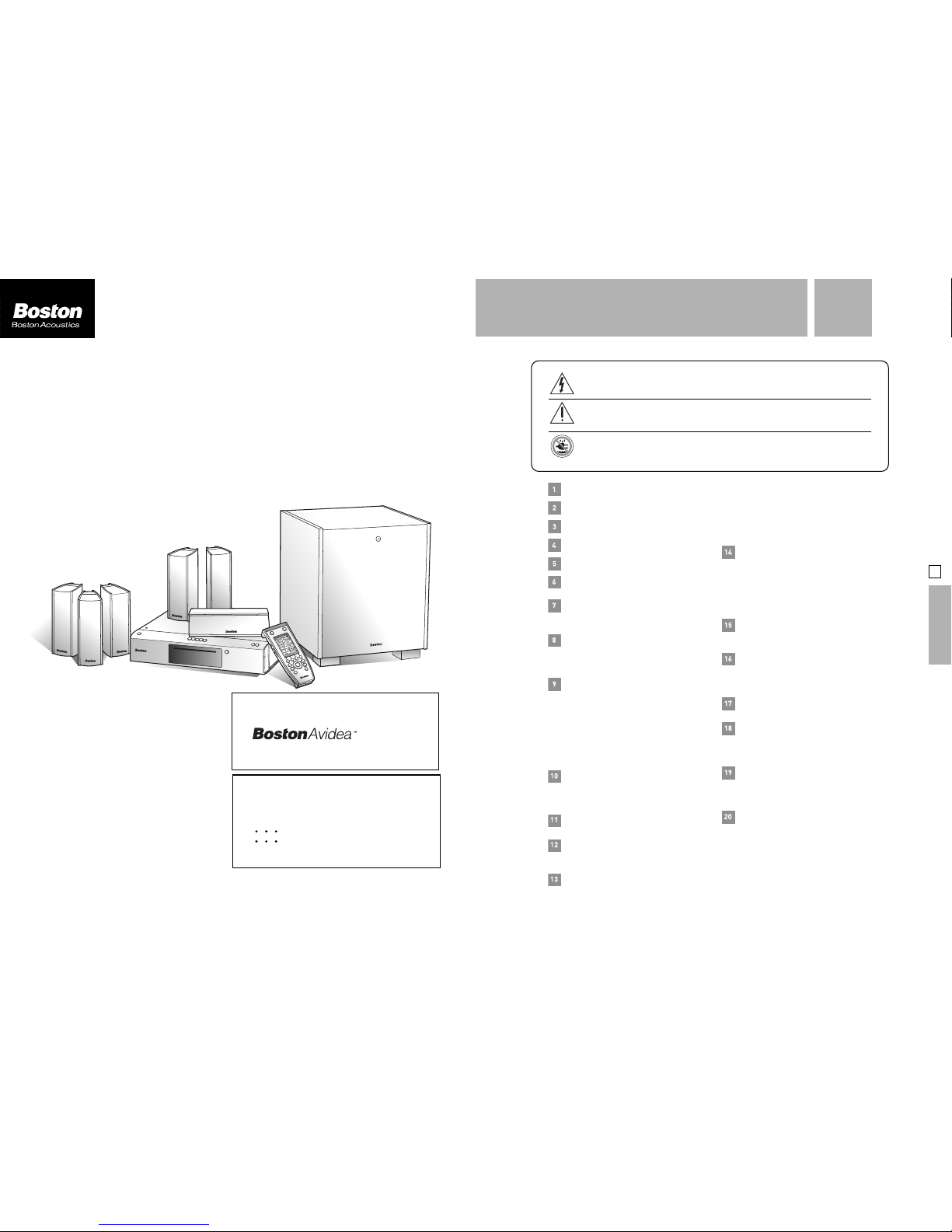
AVIDEA SYSTEM
SETUP AND USE GUIDE