Boston Acoustics DT7000 User manual

DigitalTheaterTM 7000
Integrated Home Theater System with Dolby®Digital Surround and BassTracTM
DigitalTheater™ 7000
DT7000 Manual 11/99 rev2 11/24/99 12:19 PM Page 1

1. Read these instructions.
2. Keep these instructions.
3. Heed all warnings.
4. Follow all instructions.
5. Do not use this apparatus near water.
6. Clean only with damp cloth.
7. Do not block any of the ventilation
openings. Install in accordance with
manufacturer’s instructions.
8. Do not install near any heat sources such
as radiators, heat registers, stoves, or
other apparatus (including amplifiers)
that produce heat.
9. Do not defeat the safety purpose of the
polarized or grounding type plug.
A polarized plug has two blades with one
wider than the other. A grounding type
plug has two blades and a third grounding
prong. The wide blade or the third prong
are provided for your safety. When the
provided plug does not fit into your outlet,
consult an electrician for replacement of
the obsolete outlet.
10. Only use attachments/accessories
specified by the manufacturer.
11. Unplug this apparatus during lightning
storms or when unused for long periods
of time.
12. Refer all servicing to qualified service
personnel. Servicing is required when
the apparatus has been damaged in
any way, such as power-supply cord or
plug is damaged, liquid has been spilled
or objects have fallen into the apparatus,
the apparatus has been exposed to rain
or moisture, does not operate normally,
or has been dropped.
13. Caution! Do not short output jack
of power supply!
14. Protect the power cord from being
walked on or pinched, particularly at
plugs, convenience receptacles, and the
point where they exit from the apparatus.
2
Important Safety Instructions
This symbol found on the subwoofer indicates double insulation.
This symbol found on the subwoofer indicates the user should read
all safety statements found in the user manual.
This symbol found on the subwoofer indicates hazards arising from
dangerous voltages.
Warning! To reduce the risk of fire or electric shock do not expose this apparatus
to rain or moisture.
DT7000 Manual 11/99 rev2 11/24/99 12:19 PM Page 2

American Users:
This equipment has been tested and found to
comply with the limits for a Class B digital
device, pursuant to part 15 of the FCC Rules.
These limits are designed to provide reason-
able protection against harmful interference
in a residential installation. This equipment
generates, uses and can radiate radio fre-
quency energy and, if not installed and used
in accordance with the instructions, may cause
harmful interference to radio or television
reception. However, there is no guarantee
that interference will not occur in a particular
installation. If this equipment does cause
harmful interference to radio or television
reception, which can be determined by turn-
ing the equipment off and on, the user is
encouraged to try to correct the interference
by one or more of the following measures:
1. Reorient or relocate the receiving antenna.
2. Increase the separation between the equip-
ment and receiver.
3. Connect the equipment into an outlet on a
circuit different from that to which the receiver
is connected.
4. Consult the dealer or an experienced
radio/TV technician for help.
Canadian Users:
This digital apparatus does not exceed the
Class B limits for radio noise emissions from
digital apparatus as set out in the radio inter-
ference regulations of Industry Canada.
Caution! Disconnect power before servicing.
Le présent appareil numérique n'émet pas
de bruits radioélectriques dépassant les
limites applicables aux appareils numériques
de Classe B prescrites dans le règlement
sur le brouillage radioélectrique édicté par
Industrie Canada.
Attention! Couper le courant avant'entretien.
3
Regulatory Compliance Statements
DT7000 Manual 11/99 rev2 11/24/99 12:19 PM Page 3

Declaration of Conformity
Konformitätserklärung
Déclaration de Conformité
Declaración de Conformidad
Verklaring de Overeenstemming
Dichiarazione di Conformità
We/Wir/ Nous/WIJ/Noi:
Boston Acoustics, Inc. 300 Jubilee Drive
Peabody, MA 01960 USA
declare under our sole responsibility
that the product
erklären, in alleniniger Verantwortung,
daß dieses Produkt,
déclarons sous notre seule responsabilité
que le produit,
declaramos, bajo nuestra sola responsabili-
dad, que el producto,
verklaren onder onze verantwoordeijkheid,
dat het product,
dichiariamo sotto nostra unica responsabilità,
che il prodotto,
DigitalTheater™ 7000 System
to which this declaration relates, is in
conformity with the following standards
or other normative documents:
auf das sich diese Erklärung bezieht,
mit der/den folgenden Norm(en) oder
Richtlinie(n) übereinstimmt:
auquel se réfère cette déclaration est
conforme à la (aux) norme(s) ou au(x)
document(s) normatif(s):
al que se refiere esta declaración es
conforme a la(s) norma(s) u otro(s) documen-
to(s) normativo(s):
waarnaar deze verklaring verwijst, aan
de volende noem(en) of richtlijn(en)
beantwoordt:
a cui si riferisce questa dichiarazione è con-
forme alla/e sehuente/i norma/o documento/i
normativo/i:
European Users:
This Information Technology Equipment has
been tested and found to comply with the
following European directive:
(i) EMC Directive 89/336/EEC amending
directive 92/31/EEC 93/68 EEC as per
- EN 50081-1:1992 according to
EN55022: 1994/A1: 1995/A2: 1997 Class B
EN61000-3-2: 1995
EN61000-3-3: 1995
- EN50082-1: 1997 according to
EN61000-4-2: 1995
EN61000-4-3: 1997
ENV 50204: 1996
EN61000-4-6: 1996
EN61000-4-5: 1996
EN61000-4-11: 1996
EN61000-4-4: 1995
(ii) Low Voltage Directive (Safety) 72/23/EEC
as per EN60065: 1993
4
DT7000 Manual 11/99 rev2 11/24/99 12:19 PM Page 4

Japanese Users:
This equipment is in the Class 2 category
(Information Technology Equipment to be
used in a residential area or an adjacent area
thereto) and conforms to the standards set by
the Voluntary Control Council for Interference
by Information Technology Equipment aimed
at preventing radio interference in such resi-
dential areas.
When used near a radio or TV receiver, this
equipment may become the cause of radio
interference. Read the instructions for correct
handling.
Australian and New Zealand Users:
This device has been tested and found to
comply with the limits for a Class B digital
device, pursuant to the Australian/New
Zealand standard AS/NZS 3548 set out by the
Spectrum Management Agency.
Caution! Disconnect power before servicing.
5
N-93
DT7000 Manual 11/99 rev2 11/24/99 12:19 PM Page 5

6
DIGITAL
DigitalTheater™7000
This package contains —
Remote
“AAA” Batteries (4)
Subwoofer
Center channel speaker with display
Front left and right channel speakers (2)
Surround left and right speakers (2)
Front speaker key-hole wall-mount brackets (2)
Satellite speaker wall-mount brackets (2)
Satellite speaker up-mount brackets (2)
25 ft (64cm) short front speaker cables (2)
50 ft (127cm) long surround speaker cables (2)
20 ft (51cm) control and speaker cable
Digital input cable
Analog stereo input cable
Power cord
Self-adhesive rubber feet for subwoofer (4)
Self-adhesive rubber pads for speakers (4 x 5)
Wall-mount hardware (surround speakers)
Wall-mount hardware (front speakers)
•
1
•
2
•
3
•
4
•
5
•
6
•
8
•
9
•
10
•
11
•
7
•
12
•
13
•
14
•
15
•
17
•
1
•
2
•
3
•
4
•
5
•
6
•
8
•
9
•
10
•
11
•
7
•
12
•
13
•
14
•
15
•
16
•
16
•
18
•
17
•
18
•
19
•
19
DT7000 Manual 11/99 rev2 11/24/99 12:19 PM Page 6

7
Specifications
System Frequency Response (±3dB) 35-20,000Hz
Maximum System SPL 110dB at typical listening position
Dolby Digital Decoder 20-bit DSP
Inputs Digital (2): Coaxial and optical
Analog (2): Stereo RCA Jacks
Remote Control Universal remote control with 3 pre-programmed buttons
for TV, VCR, DVD, Satellite or Cable Box.
Display (Center Channel) Alphanumeric liquid crystal display (LCD) shows input,
digital surround decoding mode, volume level and set-up
functions. 5 light emitting diodes (LEDs) show digital surround
decoding mode.
Center Channel Drive Unit 31⁄2” (89mm) woofer, 3⁄4” (19mm) dome tweeter,
actively equalized
Subwoofer Bass Unit 8” (200mm), actively equalized
Front Satellite Drive Units 31⁄2” (89mm woofer), 3⁄4” (19mm) dome tweeter,
actively equalized
Rear Satellite Drive Units 31⁄2” (89mm), actively equalized
Dimensions (H x W x D) Center Channel – 43⁄4x 117⁄8x 6” (120 x 300 x 153mm)
Subwoofer – 193⁄8x 131⁄4x 14”(490 x 337 x 355mm)
Front Satellites – 67⁄8x 41⁄4x 53⁄4” (175 x 108 x 146mm)
Surround Satellites – 41⁄2x 41⁄8x 43⁄4” (110 x 105 x 120mm)
Weight Front Satellites – 4 lbs. (2kg)
Center Channel – 4 lbs. (2kg)
Subwoofer – 41 lbs. (19kg)
Surround Satellites – 2 lbs. (1kg)
Finish Matte Black; Black Ash Vinyl Veneer (subwoofer)
DT7000 Manual 11/99 rev2 11/24/99 12:19 PM Page 7

Dolby Digital Decoder
DigitalTheater 7000 uses a state-of-the-art
Dolby Digital decoder. It accepts a digital data
stream from either of two digital inputs or con-
verts either of two stereo analog inputs to digi-
tal format. The digital data can be either
encoded Dolby Digital or linear PCM data. The
decoder automatically detects the difference.
Center Channel Unit
This integrated unit goes on top of the TV
and houses the center speaker, an alpha-
numeric display, and the infra-red remote con-
trol receiver. The center speaker is a two way
design with a 31⁄2” (89mm) copolymer bass
unit and 3⁄4” (19mm) dome tweeter.
DigitalTheater 7000 utilizes MagnaGuard®
magnetic shielding on the subwoofer and
front speakers to prevent television picture
interference or accidental disk erasure. The
pre-programmed universal remote control
operates the DigitalTheater 7000, and
hundreds of different models of TVs, VCRs
and cable boxes.
DigitalTheater 7000 Subwoofer
with BassTracTM
The DigitalTheater 7000 Subwoofer provides
dramatic bass impact. It uses our long-excursion
8-inch (200mm) bass driver in a bass reflex
enclosure. The result is a subwoofer that deliv-
ers deep, clean bass from a compact enclosure.
Because of it’s high-powered amplifier and
computer-optimized tuning, it is capable of
impressive deep bass and high output from it’s
remarkably compact enclosure. In addition, this
subwoofer features BassTracTM, a proprietary
new Boston-designed circuit that tracks the
input signal to the subwoofer and prevents its
amplifier from being driven into audible distor-
tion. The benefit: The bass stays clean and
strong at any listening level.
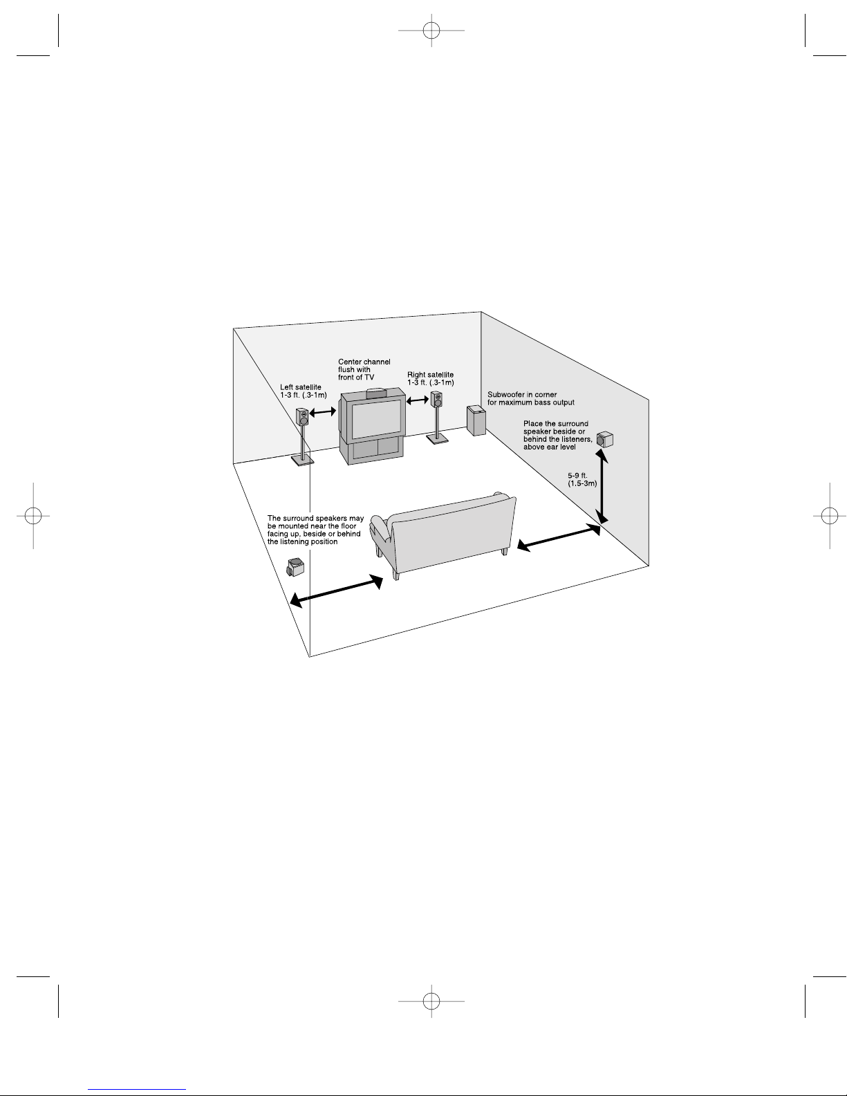
DigitalTheater 7000 Satellites
The DigitalTheater 7000 system provides
four satellite speakers for the left and right
front and left and right surround channels.
The left and right front speakers match the
center design with a 31⁄2” (89mm) copolymer
bass unit and 3⁄4” (19mm) dome tweeter.
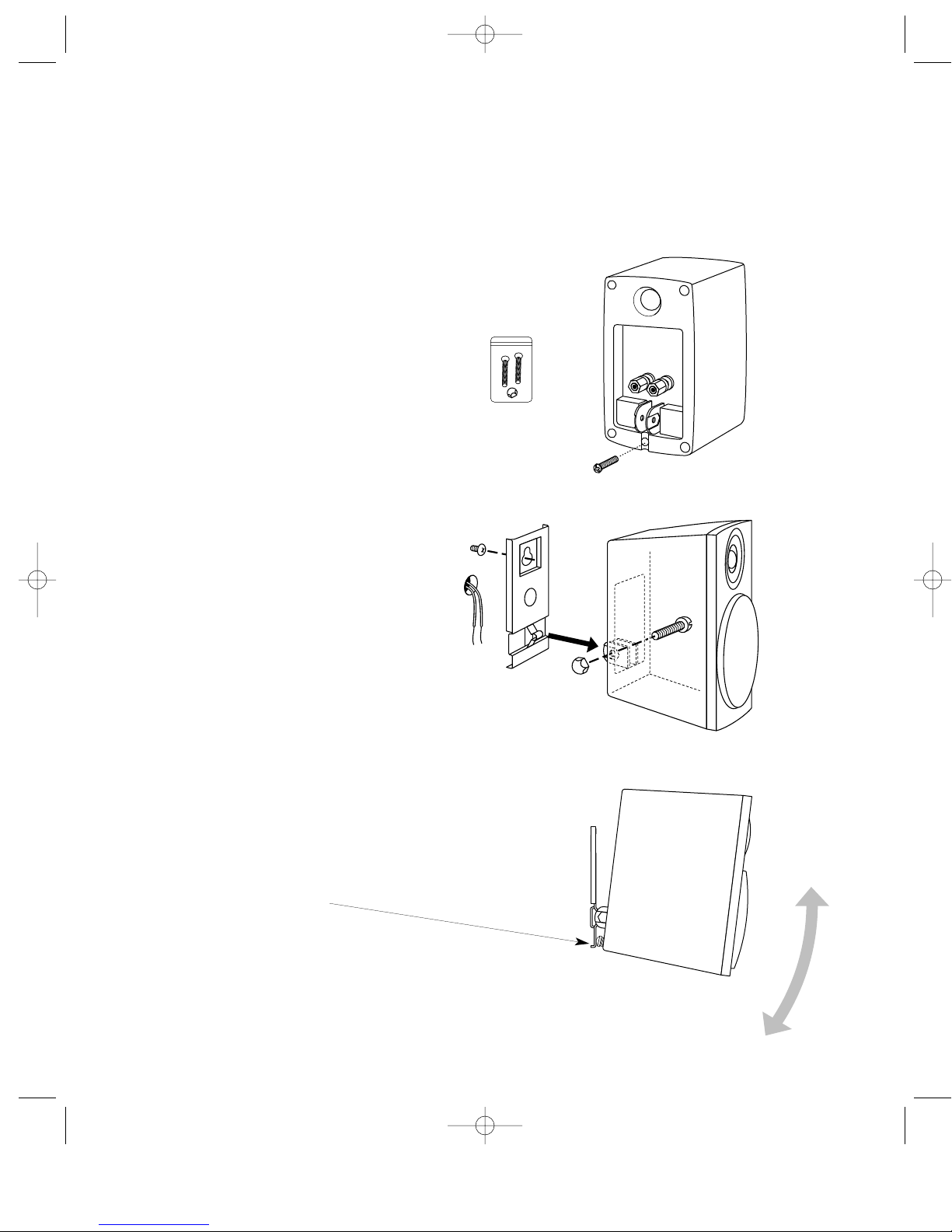
These speakers can be mounted on the
wall, using the supplied wall-mounting
brackets. Alternatively they can be placed
on a bookshelf or table-top using the rubber
feet provided.
8
Description
The Boston DigitalTheater 7000 is an integrated home theater sound system. It accepts signals
from digital or analog sources, decodes them to produce surround sound for up to six channels
and provides the amplifiers and speakers for those six channels. The power section uses separate
actively-equalized amplifiers for each of the speakers, including the subwoofer. All that is needed
is a DVD player, digital DSS satellite TV feed, or Hi-Fi VCR, and a monitor or TV for a complete
home theater system. The DigitalTheater 7000 delivers wide-range, high-fidelity sound from a
package that is easy to install and a pleasure to use.
DT7000 Manual 11/99 rev2 11/24/99 12:19 PM Page 8

Center Channel
Place the DigitalTheater 7000 center channel
on top of the video monitor or TV set. The
front of the speaker should be flush with the
front of the television.
Subwoofer
The level of bass output from the subwoofer
will vary at different positions in the room.
Corner placement provides the most bass
output, while placement near only one wall
provides somewhat less bass. Since low bass
sounds are omnidirectional—the ear can’t tell
from which direction they’re coming—the
subwoofer can be located out of sight in the
corner of the room, yet all the sound, includ-
ing the bass, appears to come from the
DigitalTheater 7000’s front speakers.
Front Satellite Speakers
The best location for the front speakers is
to either side of the video monitor or TV.
The speakers can be wall-mounted, or placed
on a bookshelf, with equally good results.
Rear Satellite Speakers:
The best location for the rear speakers is
to the side and slightly behind the listeners.
The speakers can be wall-mounted facing
out, as shown. It may be easier to run wire
to the speakers if they are mounted near
the floor, facing up towards the ceiling. This
position will produce excellent surround
results. Mounting brackets for both options
are included.
9
How to Place the Boston DigitalTheater 7000
System in Your Room
DT7000 Manual 11/99 rev2 11/24/99 12:19 PM Page 9

10
Using the Wall-Mount Bracket
The front left and right satellites may be wall-mounted using the included keyhole bracket. An
optional pedestal shelf stand/wall-mount bracket (Model MRB) is available that provides greater
positioning flexibility. For more information, contact your dealer or Boston Acoustics directly.
Install a #8 or #10 mounting screw
on the wall (not supplied - consult a
knowledgable installer regarding the
proper hardware to use on your wall).
Attach the bracket to the back
of the speaker with the other
1⁄4-20” machine screw and acorn
nut as shown.
If you are running wires behind the
wall, make a 3⁄8” (9.5mm) wire hole,
13⁄4” (44mm) below the mounting
screw for the wire.
Insert one of the 1⁄4-20” machine screws
into the threaded insert on the back of the
satellite as shown.
A
B
•
1
•
1
•
2
•
2
•
3
•
3
C
Angle the speaker as desired, then adjust the
machine screw against the keyhole bracket to
hold the speaker’s position.
DT7000 Manual 11/99 rev2 11/24/99 12:19 PM Page 10

3/4"
(19 mm
115/32"
(37mm)
Drill 7/16" (11mm) holes
for toggle wings
6–32 x 2"
machine screws
flathead machine screw
Drill two 7⁄16” (11mm) holes for toggle wings.
If mounting on a surface other than drywall,
consult a knowledgeable installer about the
proper hardware to use on your wall.
If you are running speaker wire behind the wall,
drill a 1⁄2” (12mm) hole 3⁄4” (19mm) below the top
toggle wing hole.
Attach bracket to speaker with the supplied
flathead machine screw.
Drill two 1⁄8” (3mm) pilot holes for wood screws,
then mount screws. Leave about 1⁄8” (3mm) of
screw thread exposed. If mounting on drywall,
use plastic anchors (not included). Consult
a knowledgeable installer about the proper
hardware to use on your wall.
Attach bracket to wall with machine screws
and toggle wings as shown.
Connect the speaker wire to the speaker.
Attach speaker bracket with flathead
machine screw.
If you are running speaker wire behind the
wall, drill a 1⁄2” (12mm) hole 1" (25mm) below
the top screw hole.
Connect the speaker wire to the speaker.
Slip the bracket/speaker assembly onto
the screws.
11
2 5/32"
(55mm)
1"
(25mm)
#9 x 1" wood screws
flathead machine screw
Facing Up
Wall-mounting the surround satellite speakers
Facing Out
•
1
•
2
•
3
•
4
•
5
•
1
•
2
•
3
•
4
•
5
•
1
•
2
•
3
•
4
•
5
•
1
•
2
•
3
•
4
•
5
DT7000 Manual 11/99 rev2 11/24/99 12:19 PM Page 11

How to Wire Your Speakers
You need to wire your speakers correctly to obtain the best sound quality and the proper image.
Wiring should just take a few minutes, but it’s important to do it carefully, since incorrect wiring
(such as reversed connections) can result in a poor soundstage or poor bass.
The DigitalTheater 7000 includes all the
necessary speaker wire required for an aver-
age sized room installation. All the wires are
18 gauge and have pre-stripped bare wire
leads that connect to the speaker. Be sure to
maintain the consistency of the + (red)
and – (black) speaker connections by using
the markings on the wire’s insulation.
IMPORTANT: On all the speakers, connect
the red terminal to the bare wire lead that
has the “+” sign on it’s insulation. Connect
the black terminal to the other bare wire lead
that has either the word “Boston” or the wire’s
identification information on it.
Left and Right Front Satellites
and Center Channel
Using the five-way binding posts: The binding
posts permit easy connection to banana plugs,
pins, spade lugs, and bare wire. The metal sur-
faces are plated with gold to prevent corrosion.
NOTE: Before using banana plugs, first remove
the red and black plastic CE safety insert caps.
Surround Satellites
Push down the buttons and insert the wire
where shown. Be sure to connect + to + (red)
and – to – (black).
12
Insert the wire in the hole and tighten
DT7000 Manual 11/99 rev2 11/24/99 12:19 PM Page 12

Speaker Connection
Center Channel Speaker
Connect the short speaker cable, with the green RCA plug, between the green jack on
the DigitalTheater 7000 subwoofer marked center and the speaker cable jack on the center
channel speaker.
Connect the control cable, with blue mini-DIN plug on both ends, between the jack on
the DigitalTheater 7000 subwoofer marked control and the control cable jack on the center
channel speaker.
Satellite Speaker Connections
There are four satellite speakers, two for
the front and two for the rear. The larger
front speakers use the shorter cables,
and the smaller rear surround speakers use
the longer cables. Connect them as shown:
Plug the white plug of the short speaker
cable into the jack labeled left front.
Plug the red plug of the short speaker cable
into the jack labeled right front.
Plug the white plug of the long speaker
cable into the jack labeled left surround.
Plug the red plug of the long speaker cable
into the jack labeled right surround.
13
DT7000 Manual 11/99 rev2 11/24/99 12:19 PM Page 13

Input Connections
DVD in: The the DigitalTheater 7000 may
be connected to the digital output from any
DVD player.
Note: DigitalTheater 7000 cannot be con-
nected to the AC-3 output from a laserdisc
player since a laserdisc is RF modulated. If
you wish to use a Dolby Digital laserdisc play-
er (with an “AC-3 RF output”), consult your
dealer for a suitable adaptor.
To make the connection, use the black digital
input cable. Plug one end into the digital
output of the DVD player and the other into
the black digital terminal on the subwoofer
back panel.
DSS in: The DigitalTheater 7000 may be con-
nected to the digital output from any DSS
satellite television system that provides a digi-
tal audio output. To make this connection, use
an optical digital cable like our DC-12 (not
included — for more details, contact your
dealer or Boston Acoustics directly).
Plug one end into the digital output of the
DSS unit and the other into the DSS jack on
the subwoofer back panel.
Note: Depending on it’s digital
output, any digital source
(DVD, MD, CD, satellite) can be
connected to either the optical
or coaxial (wired) digital inputs.
VCR and Audio in: The two stereo analog
inputs on the DigitalTheater 7000 may be
connected to any stereo analog source.
Typically this will be a stereo TV, Hi-Fi VCR, or
CD player. To make the connection, use the
analog stereo cable. Plug one end into the
audio outputs of the source unit and the other
into the appropriate terminals on the sub-
woofer back panel. Make sure the correct
color plug is connected to the correct color
jack: red to red and white to white.
14
Source Connection
DT7000 Manual 11/99 rev2 11/24/99 12:19 PM Page 14

Center Channel Display
Alphanumeric Display
This display shows the chosen input and the setting for system master volume, and the individual
channel levels (“trim levels”) for the center speaker, surround speakers, and subwoofer. The
master volume is numbered between 0 and 80, the trim levels for the center and surround speak-
ers are between –9 and +9, and the trim level range for the subwoofer is between -9 and +15.
The display dims after 5 seconds. When DigitalTheater 7000 is muted, the display reads “mute”.
The system can be unmuted by pressing the mute button, the volume up or down buttons, or any
input or system mode button. Following a choice of input or mode, the display also shows the
audio format (Dolby Digital, etc). After making any adjustments, the display will return back to the
chosen input and master volume and will then dim after 5 seconds.
Mode Group
Dolby Digital
This LED illuminates when the user has selected either the DSS or DVD input, and the
system’s decoder has detected a Dolby Digital signal.
night mode
For low level listening, (late at night, for example), the quietest passages can be difficult to hear
and the loud passages are often too loud. The night mode reduces the system’s dynamic range
(the difference between loudest and softest sounds) so the quiet parts of the program are clearly
audible even at low volume, while attenuating the loudest passages so others aren’t disturbed.
NOTE: The night mode can only be used when Dolby Digital is active. Because it is software-
dependent, its effect can be subtle, depending on the particular program.
PCM
This LED illuminates when the user has selected either the DSS or DVD input, and the
system’s decoder has detected a PCM signal.
15
•
1
•
2
DT7000 Manual 11/99 rev2 11/24/99 12:19 PM Page 15

•
1
•
2
LED Display Panel On Center Channel Unit (cont.)
Pro Logic
This LED illuminates when either the Audio or VCR input is selected and the 5-ch mode on the
remote control is selected. This LED will also illuminate in addition to the Dolby Digital LED when
the DigitalTheater 7000 is sent a digital signal from a DVD player, but for some reason, either the
software or the source unit is not configured for 5.1 channel digital operation. See NOTE below.
NOTE: For 5.1 channel digital playback, confirm that your software supports 5.1 channel
playback and select “5.1” on the DVD’s main title screen. Also be sure that your DVD player
is configured for Dolby Digital operation by selecting “Dolby Digital” from your DVD player’s
set-up menu. Refer to the instructions that came with your DVD player.
2-ch stereo
This LED illuminates when the 2-ch mode is selected. 2-channel operation may be selected at any
time, with any input. Sound will only be heard through the left and right speakers (plus sub-
woofer) during 2-channel operation.
16
Numeric Level Indicator
Operational Mode
•
1
•
2
DT7000 Manual 11/99 rev2 11/24/99 12:19 PM Page 16

Boston power Turns DigitalTheater 7000 on
and off.
power Turns devices used with
DigitalTheater 7000 on or off. Press the
button (TV, VCR or cable)for the unit you
wish to turn on or off and then power.
Numeric Keypad Used for entering the TV,
VCR, cable box, or DSS channel number
and programming the remote.
Channel and Sound Group These five buttons
control the TV ,VCR, cable box, or DSS
channel up or down, sound volume of
the DigitalTheater 7000 up or down, and
muting the DigitalTheater 7000.
VCR Group Controls the VCR or DVD—
play, pause, stop, fast forward, rewind
and record. NOTE: The record button
must be pressed twice to engage the
record function to prevent accidental
recording. The record button is inopera-
tive when used on a DVD player.
Sound Input and Night Mode Pressing the
DVD or DSS button selects the DVD or
DSS input. Pressing either button a sec-
ond time engages the system’s night
mode, to make quiet passages more
intelligible at low volumes and loud pas-
sages less intrusive.
5-ch/2-ch Pressing the 5-ch/2-ch button
turns the surround decoder on and off.
NOTE: For 5.1 channel digital playback, con-
firm that your software supports 5.1 channel
playback and select “5.1” on the DVD’s main
title screen. Also be sure that your DVD player
is configured for Dolby Digital operation by
selecting “Dolby Digital” from your DVD play-
er’s set-up menu. Refer to the instructions that
came with your DVD player.
When the 5-ch/2-ch button is pushed again,
the sound becomes 2-channel stereo (the 2-
ch LED will illuminate). Sound will be heard
from the left and right channels plus sub-
woofer. There is no output from the center or
surround channels.
When the surround decoder is engaged on
stereo material by pressing the 5-ch/2-ch but-
ton, the Pro Logic LED will illuminate. In this
17
VOL- VOL+
CH +
CH -
MUTE
V
C
R
T
V
c
a
b
l
e
p
o
w
e
r
s
e
t
u
p
p
o
w
e
r
B
o
s
t
o
n
enter previous
rew
paus
play
stop
fast fwd
record
VC
5-ch / 2-ch test tone
L front R frontcenter
L Rsubwoofer
Audio
DVD/night
DSS/night
pause
R
rear rear
•
1•
2
•
3
•
4
•
5
•
6
•
7
•
8
Universal Remote Control
The DigitalTheater 7000 comes equipped with a universal remote control which will operate
many TVs, VCRs, cable boxes, DVD players, and DSS units, as well as the DigitalTheater 7000
itself. This means only one remote control is needed to watch a movie, eliminating the clutter of
multiple remotes.
•
1
•
2
•
3
•
4
•
5
•
6
•
7
DT7000 Manual 11/99 rev2 11/24/99 12:19 PM Page 17

Universal Remote Control (cont.)
(see Remote Control illustration on page 17)
case, there is usually output from all the
speakers, even though the source material
has not been encoded in the Dolby Surround
format. NOTE: Programs recorded in mono
will appear only in the center channel when
surround is activated.
Many listeners enjoy the three-dimensional
effect of regular stereo material played
through the Surround decoder.
previous When using the remote to con-
trol your television, pressing this button
reverts to the previously viewed channel
(if your television has this function).
Programming the Universal Remote Control
This universal remote is pre-programmed for
hundreds of different devices.
Install the 4 “AAA” batteries in the remote.
Orient the batteries (+ or -) as shown
in the battery compartment.
For your TV, VCR, cable box, DSS, or DVD
player, look up the three-digit code for your
particular model in the included booklet.
Press the button for the unit you wish to
program—TV, VCR or cable box. The
LED on the remote will blink.
• The VCR button can also be used to
program DVD player codes, in place of
the VCR.
• The cable button can also be used to
program DSS codes, in place of the
cable box.
18
VOL- VOL+
CH +
CH -
MUTE
V
C
R
T
V
c
a
b
l
e
p
o
w
e
r
s
e
t
u
p
p
o
w
e
r
B
o
s
t
o
n
enter previous
rew
paus
play
stop
fast fwd
record
VC
5-ch / 2-ch test tone
L front R frontcenter
L Rsubwoofer
Audio
DVD/night
DSS/night
pause
R
rear rear
•
8
•
1
•
1
•
2
•
3
•
4
DT7000 Manual 11/99 rev2 11/24/99 12:19 PM Page 18

Hold the setup button on the remote
control for about three seconds, until the
LED on the remote blinks twice.
Enter the three-digit code for your particu-
lar device. The LED on the remote will blink
once after the first two numbers are
entered, and twice after the last number is
entered to signify it has accepted the pro-
gramming. Example: 1 (blink), 2 (blink), 3
(blink-blink). A single long blink indicates
an invalid key sequence.
Test the remote control on your device by
pressing power on or off.
If the remote does not appear to be working,
check that the right code was programmed.
Many manufacturers have multiple codes for
different devices; if the first code doesn’t
work, try a different code. Make sure the LED
on the remote blinks every time a button is
pressed. If not, be certain the batteries are cor-
rectly installed or replace the batteries in the
remote control.
Button Reassignment to Control
Different Devices
You might have two devices that would be
controlled by the same button (a VCR and a
DVD, for example, each controlled by the VCR
button, or a cable box and DSS, each con-
trolled by the cable button). In that case, you
will have to reassign one of the other buttons
to control that device.
Example: If you have a VCR and DVD player,
you will need to reassign the cable button to
control the DVD player
Press setup
Press 992 on the numeric keypad
Press the source button (in this example,
the VCR button)
Press the destination button (in this
example, the cable button)
The cable button is now another VCR button,
which can be used to control a DVD player.
Program the remote as described in steps 1-4.
19
VOL- VOL+
CH +
CH -
MUTE
V
C
R
T
V
c
a
b
l
e
p
o
w
e
r
s
e
t
u
p
p
o
w
e
r
B
o
s
t
o
n
enter previous
rew
paus
play
stop
fast fwd
record
VC
5-ch / 2-ch test tone
L front R frontcenter
L Rsubwoofer
Audio
DVD/night
DSS/night
pause
R
rear rear
•
2
•
3
•
4
•
5
•
6
•
8
•
7
•
5
•
6
•
7•
8
DT7000 Manual 11/99 rev2 11/24/99 12:19 PM Page 19

Press test tone, and the test tone is heard
moving clockwise from speaker to speak-
er at 2 second intervals. The center chan-
nel display indicates the speaker under
test. The order should be left front, cen-
ter, right front, right rear and left rear. (No
test tone is heard from the
subwoofer. Adjust the subwoofer level
independently of the other channels
according to personal taste or to com-
pensate for the effects of room place-
ment). If the tone does not move contin-
uously from speaker to speaker then one
or more speakers is not connected to the
correct output on the subwoofer.
As the test tone rotates around the speakers,
you may notice that some speakers are louder
or softer than others. This is not due to any
defect, but to the difference in room acoustics
at different locations. The speaker levels
should be individually adjusted so they all
appear to have the same loudness at the lis-
tening position.
To adjust a specific speaker’s volume—
Press the button for the speaker you wish
to adjust. The display on the center chan-
nel speaker will indicate for the speaker
selected and the test tone will continue
to circulate.
Press the volume up or down button to
raise or lower the level of the selected
speaker. After 5 seconds, the function of
the volume button reverts to Master
Volume control.
Press test tone again to turn it off.
To adjust the subwoofer volume—
Press the subwoofer button (the display
indicates the subwoofer is undergoing
adjustment).
Press the volume button to raise or lower
the subwoofer level.
Even after calibrating the system, you may
want to adjust the loudness levels of the
center, satellite, or subwoofer channels to
personal taste. Speaker levels can be adjust-
ed at any time by selecting the speaker and
using the volume control.
20
VOL- VOL+
CH +
CH -
MUTE
V
C
R
T
V
c
a
b
l
e
p
o
w
e
r
s
e
t
u
p
p
o
w
e
r
B
o
s
t
o
n
enter previous
rew
paus
play
stop
fast fwd
record
VC
5-ch / 2-ch test tone
L front R frontcenter
L Rsubwoofer
Audio
DVD/night
DSS/night
pause
R
rear rear
Initial Setup – Test Tone
Before using the system, the relative speaker levels should be calibrated for optimum perform-
ance. This is easily accomplished by using the system’s built-in test tone to match the levels of the
front and rear channels. The test tone button on the remote control generates the test tone for
calibrating the speakers.
•
1
•
2
•
3
•
4
•
5
•
6
•
1
•
2
•
3
•
4
•
5
•
6
DT7000 Manual 11/99 rev2 11/24/99 12:19 PM Page 20
This manual suits for next models
1
Table of contents
Other Boston Acoustics Home Theater System manuals

Boston Acoustics
Boston Acoustics Bassett's Nvelop User manual

Boston Acoustics
Boston Acoustics Avidea 770 Safety guide

Boston Acoustics
Boston Acoustics Avidea 610 User manual

Boston Acoustics
Boston Acoustics MCS 160 User manual

Boston Acoustics
Boston Acoustics TVee Model Two User manual

Boston Acoustics
Boston Acoustics TVee Model Two User manual

Boston Acoustics
Boston Acoustics DT6000 User manual

Boston Acoustics
Boston Acoustics TVeeTM User manual

Boston Acoustics
Boston Acoustics Avidea 610 Technical manual

Boston Acoustics
Boston Acoustics TVee 22 User manual